adsense analytic

Showing posts with label reinforced concrete. Show all posts

Monday, August 26, 2019

Uses of prestressed concrete in civil engineering

Prestressed concrete is suitable for different types of structural systems which range from pre-tensioned and post-tensioned structures, both cast-in-place and precast, and other pre-stressed components along with normally reinforced concrete.
Pre-stressed and precast concrete is divided in following four major categories:
• Standardized Elements
• Fixed Cross Section Elements
• Fully Engineered Elements
• Precast Nonprestressed Elements
Standardized Precast Prestressed Elements
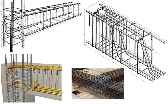
Pretensioned concrete beams and slabs are normally built up in recyclable steel forms in a precast plant. Though a humble amount of custom formwork is utilized at precast plants, but when standardized components are utilized, the quality becomes better and the costs are decreased.
They comprises of standard sections like single-T and double-T beams, box girders, hollowcore slabs, inverted T-beams, and bridge girders. With the capital investment, it is possible to build up and equip a precast plant with the concrete mixing equipment, forms, stressing beds, curing systems, and heavy lifting equipment.
To increase ROI, the forms and stressing facilities should be applied continually. By improving the production process, the precast pieces can be fabricated on a routine and regular basis.
The cost efficiencies of this type of fabrication allow the architects and engineers to choose the sections for an extensive range of applications and ensure accessibility and competitive cost. Hollowcore planks, single-T, and double-T beams are applied as floor elements in building construction.
Fixed Cross Section Elements
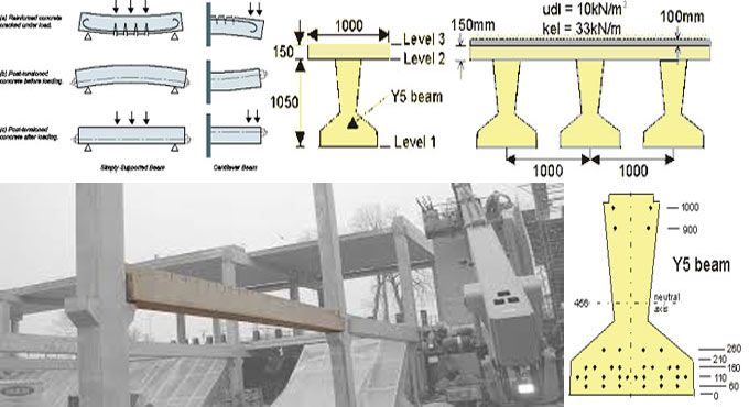
The design engineer takes the responsibility to find out the pre-stressing forces and tendon locations in fixed cross section situations. Two common fixed section design conditions belong to post-tensioned beams and slabs for developing or parking garage construction, and girders for bridge construction.
Other uses of fixed section components range from structures like water tanks and post-tensioned slabs on-ground.
Fully Engineered Elements
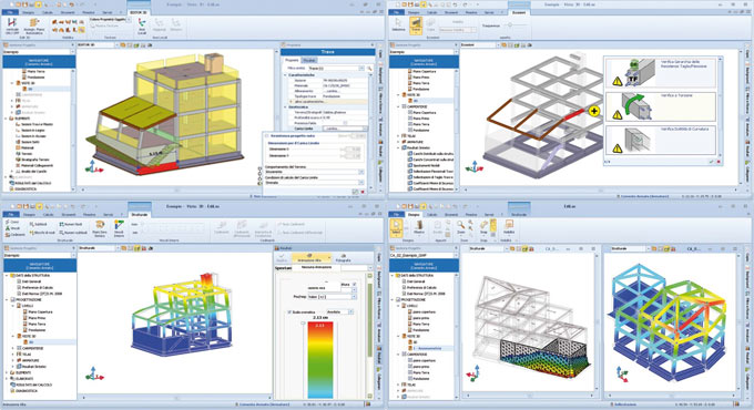
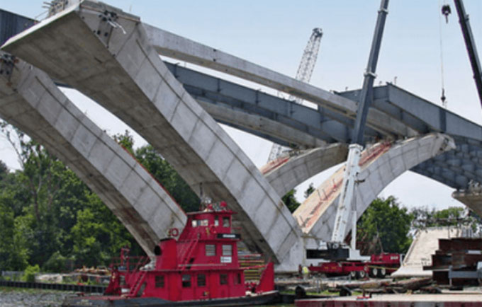
For fully engineered elements, there should be constant detailed engineering all through design and construction. Instances of fully engineered structures are segmental bridges, specialty transit structures, tanks, towers, stadiums, floating facilities, and unusual building construction. The design of these structures is based on significant engineering effort as well as on-site inspection.
The intricacy of these structures requires the basic understanding of structural behavior, loads, prestressing effects, and material behavior. Collaboration of efforts among engineers, precast plants, and general contractors is essential.
Precast Nonprestressed Elements
The significant variation in grouping is that pretensioned elements need significant plant capitalization and stressing beds. Precast pieces are fabricated on the jobsite or in a facility devoid of stressing beds and other equipment related to a plant operation. Tilt-up walls are good instances of on-site precasting.
If a small amount of prestressing is necessary for delivery, erection or final loads, it is arranged in the form of single-strand post-tensioned tendons. The instances of precast nonprestressed elements are architectural precast panels and tilt-up construction. Architectural precast panels are utilized either as structural elements or the exterior finish of buildings.
Uses of prestressed concrete in civil engineering
~~~~~~~~~~~~~~~~~~~~~~~~~~
Published By
Rajib Dey
www.constructioncost.co
~~~~~~~~~~~~~~~~~~~~~~~~~~

Wednesday, March 13, 2019

Clear Cover and Nominal Cover used for RCC Structure

The concept of Clear cover and nominal cover is seen in the Reinforced concrete structures.

Reinforced concrete structures have been main structural materials for over a century and still the most popular material for public structures all over the world. The concrete structure is durable enough to keep its shape for a long time.

The reinforced concrete structure refers to the members like beams, boards, columns, and roof trusses etc. which are consisted of concrete and steel bars.

In these structures, the steel bars are covered by concrete but their mechanical properties will still lose due to the fire to destroy the whole structure.

In this design of reinforced concrete structures, the provided reinforced is inserted in the concrete upto a particular distance from the face of the member as there are some reasons.

The reasons are discussed below:

• It will provide protection to reinforcement from erosion
• It will also provide fire resilience to reinforcement.
​• It will also supply sufficient embedded depth so that reinforcement grows the requisite stress.


This distance is measured in various ways and known by different names like:

• Clear cover: This is the difference from the face of the member to the outermost face of the reinforcement including shear or torsion Stirrups or links.
• Nominal cover: This cover is like the same as Clear Cover although it has different name; actually the name is a term that is used by the code. It is the distance measured from the face of the member to the outermost face of the reinforcement including Stirrups or links.


To get information on other clear cover and nominal cover, go through this useful civil engineering video tutorial.


Video Source: CE&T-Civil Engg & Technology

~~~~~~~~~~~~~~~~~~~~~~~~
Published By
Rajib Dey
www.constructioncost.co
~~~~~~~~~~~~~~~~~~~~~~~~

Friday, February 22, 2019

LIMIT STATE DESIGN: (A Text-book of Reinforced Concrete Structures)

Dr. Ram Chandra, M.E. (Hons.), B.E., M.I.E., Ph.D (Roorkee), Professor of Structural Engineering has written an exclusive e-book alias LIMIT STATE DESIGN: (A Text-book of Reinforced Concrete Structures).

In this book, the author briefly explains each basic concept, elementary method, equation or theory of interest to the student of reinforced concrete design in simple manner. S.I. system of units and new code IS: 456-1978 are fully utilized in the text.

The book is specifically designed for degree, diploma and A.M.I.E. students in different branches of engineering. This book on ‘Limit State Design’ is based on the provisions of code IS: 456-1978. Both the topics of this subject, ‘Limit State of Collapse’ and ‘Limit State of Serviceability’ are clearly explained to design the reinforced concrete structures and the structural elements.

Given below, some exclusive features of the book :-

a. Each topic presented is described in detail.
b. This book is entirely composed of SI system of units and with adherence to the Indian Standard specifications (IS: 456-1978) all through the text.
c. The text of this subject is started, presented and explained in such a manner that is suitable for the students.
d. The different notations applied all through throughout this text book adhere to code of practice IS: 456-1978.

e. A number of design examples are provided in each chapter to demonstrate the theory and practice. Unsolved design problems are also provided in each chapter.
f. The diagrams clearly demonstrate the detailing of reinforcement.
g. This book abides by the current design practice.


To access the book online, click on the following link. www.amazon.in

LIMIT STATE DESIGN: (A Text-book of Reinforced Concrete Structures)

~~~~~~~~~~~~~~~~~~~~~~~~
Published By
Rajib Dey
www.constructioncost.co
~~~~~~~~~~~~~~~~~~~~~~~~


Friday, December 21, 2018

Some useful tips on reinforced concrete design

While designing the reinforced concrete members, it is necessary to check the steel reinforcement in jobsite prior to arrange concrete. Besides, ensure the concrete foundations, beams, columns, etc. are constructed as per design norms. Often, it is observed that steel beam stirrups employed in reinforced concrete design, are not installed properly.

The beam stirrups are extensively utilized in residential construction. In order to produce perfect architectural design and satisfy building occupant requirements, the sizes of concrete beam are made thinner and their lengths are increased.

In our experience, this has been the result of architectural design and. The higher cost of foundation components like drilled piers is also a major concern. To lessen the requirement of extra piers, the lengths of concrete beam are raised and it leads to the application of steel stirrups.

Concrete beams differ in depth. The shear strength of the beam will be increased by making beam deeper. For insufficient depth, steel stirrups should be included to raise the shear strength of the beam. These stirrups generally belong to one piece of steel that is twisted into a rectangular shape. Often small diameter steel like #3 and #4 rebar is applied. The stirrup normally wraps around the bottom and top bars of the beams.

It is essential to indicate the size, distance and position along the length of the beam where the stirrups will be assigned. Besides, the dimensions of stirrup should also be indicated in the sections in order that the stirrup is manufactured before installation.

Stirrups are suitable for the areas of high shear, like bearing points and under large point loads.

The installer should take proper care for fabrication of the stirrup from one piece of steel and sufficiently overlap each end (speak to the Structural Engineer or refer to the ACI code for variations). Sometimes, the stirrup is not pre-fabricated and the installer attempts to produce the stirrup in the field, once the horizontal bars are already in position. It is normal since the stirrup is built up from two pieces with insufficient lap splice.

The method is simple to set up a stirrup simultaneously the horizontal reinforcement is being installed. To avoid last-minute modifications, it is recommended to consult with the Structural Engineer with any confusion regarding size, shape, spacing and installation of stirrups before inspection.

Some useful tips on reinforced concrete design

Read more
~~~~~~~~~~~~~~~~~~~~~~~~
Published By
Rajib Dey
www.constructioncost.co
~~~~~~~~~~~~~~~~~~~~~~~~

Friday, August 31, 2018

Definition and categorisation of Pre-Stressed Concrete

Normal concrete structure contains greater compressive strength and very weak tension strength. For the purpose of removing the weakness of concrete in tension, pre-tensioning method is applied. Pre-stressed concrete belongs to the autonomous formation of permanent compressive stresses in a structure to enhance its behavior and strength toward different service situations.

Categorization of Pre-stressed concrete

Pre stressed concrete structure is categorized on the basis of their features of design and construction. The are categorized into the following three groups.

1. Location of construction
2. Level of construction
3. Method of pre-stressing


LOCATION OF CONSTRUCTION
Here, the pre-stressed structure may come as precast cast, cast in situ, composite constrictions.


PRE CAST
Precast pre-stressed components are fabricated in a plant or adjacent to the working site. Then they are conveyed to construction site and then they are constructed and set to its position.


CAST IN SITU
The cast-in-situ concrete is standard concrete that is poured into the exact formwork on the site and cured to attain the strength of RCC elements. So, the transportation and erection process are not necessary in this method.


COMPOSITE CONSTRUCTION
Composite construction is done by integrating both prestressed and cast in situ methods. As for instance, in a beam in a building structure is built up by pre-stressed concrete and the top roof slab is built up by the cast in situ method.


LEVEL OF PRE-STRESSING
Level of pre-stressing is categorized as completely pre-stressed, limited pre-stressed, partially pre-stressed.


FULLY PRE-STRESSED
In fully pre-stressed concrete members, there is not any tensile stress under the operation of working or service loads.


LIMITED PRE-STRESS
Members are pre-stressed to a limited extent in order that members may create some tensile stress under working loads but the magnitude is below the tensile strength of concrete. These members function as a completely pre-stressed member and remain uncracked under working loads.


PARTIALLY PRE-STRESSED
Partially pre-stressed structure contains both pre-stressing steel and reinforcing steel to withstand working load.


Partial pre-stressing is useful for both pre-stressed concrete and reinforced concrete. The tensile stress remains within the limit.

To get more detail, go through the following link learntocivilfield.com

Definition and categorisation of Pre-Stressed Concrete

~~~~~~~~~~~~~~~~~~~~~~~~
Published By
Rajib Dey
www.constructioncost.co
~~~~~~~~~~~~~~~~~~~~~~~~

Thursday, August 30, 2018

EdiLus-RC – A powerful software for concrete design & reinforced concrete structural calculation

EdiLus-RC is an exclusive software for making perfect concrete design that deals with structural calculations toward new and subsisting buildings in reinforced concrete by means of the most simple and effective SMART BIM object input.

The first structural calculations BIM software for reinforced concrete buildings.

To use the software, just draw the structural members to input nodes, loads, constraints… the computational model is fully ascertained from the drawing automatically.

With this software, it is possible to design and measure new buildings as well as accomplish checks and structural redevelopments of subsisting reinforced concrete buildings with cladding work, platings, FRP interventions, etc. Particular functions will help in obtaining information concerning the subsisting structure, the material strengths defining its reinforcements.

It is also possible to insert new roof structures to the subsisting building, elevations, or even extra floors, etc., and then move on to an overall validation.

Finite Element Method solver integrated in the software: A FEM solver is added with the software to provide a unitary experience in structural design. Graphical input, the static and dynamic calculations, structural analysis, modifications and construction documents (charts, tables and reports) are all created with the very same software in a simple and incorporated manner.

Graphical analysis of the calculation results: Each object is illustrated with its stress and deformation values once the calculation process is completed. Besides, the detailed calculation leads to numerical form, EdiLus also offers different graphical views that facilitate you to realize how the structure functions at a glance. The process for improvidngh the static or dynamic behaviour of the structure is simple and intuitive.

Object oriented modelling, 3D input based on Magnetic Grids: Design with intelligent objects that comprises of information concerning their characteristics of resistance and spatial location.

The complicated spatial structures can now be easily modeled with Magnetic Grids, the robust tool that facilitates you to develop a network of magnetic points in space where the different structural components are automatically attached.

Automatic reinforcement schedules design: EdiLus can design the reinforcement schedules for all structural members efficiently. A trouble-free and robust editor that facilitates you to freely adjust the reinforcement bars even after the calculation with an immediate re-verification of the structural element.

Structural checks and Technical Reports: EdiLus-RC examines structural elements sections as per the EUROCODES technical provisions and regulations. Structural engineers can easily select the national annex and the response spectrum concerning the country in which the calculations should be done.

Cost Estimating integrated with structural design: The modelled structure creates a dynamic Bill of Quantities automatically, in reality, the complete project, and any consequent variations, are instantly updated in the project’s cost estimate.

Incorporation with the Edificius BIM model: With integration of EdiLus in Edificius, Architecture and Structural engineering issues can be easily interacted facilitating the structural engineer to design and compute all the structural elements precisely.

To download a free trial version, click on the following link www.accasoftware.com

EdiLus-RC – A powerful software for concrete design & reinforced concrete structural calculation

~~~~~~~~~~~~~~~~~~~~~~~~
Published By
Rajib Dey
www.constructioncost.co
~~~~~~~~~~~~~~~~~~~~~~~~

Tuesday, March 27, 2018

Some useful notes on steel structure

Sami Ullah, the eminent engineer, presents another useful video tutorial for civil engineering students. This video provides detail information on steel structures.

Standard bar splices (lapping length for the steel) for tension member applicable to all members :-


For nos #3, 4 and 5 bars splice length is = 12 inches
For no #6 bar splice length = 22 inches
For no #8 splice length = 40 inches
General notes:
All the positive (bottom) reinforcement is demonstrated as solid lines in the drawing.
All the negative (top) reinforcement as a dashed alias broken line in the drawing.
Clear cover for slab = 0.75 inches
Clear cover for beam = 1.5 inches
Clear cover for column = 1.5 inches
Clear cover for foundation = 2.5 inches
The applied concrete should contain a minimum 28 day’s cylinder crushing strength of 3000 psi.
Splice length of steel for M20 concrete :-
Slab = 60d
Column = 45d
Beam = 60d
Here, d denotes dia of steel that is utilized in a slab.
To get more details, watch the following video tutorial.
Video SourceSami Ullah

~~~~~~~~~~~~~~~~~~~~~~~~
Published By
Rajib Dey
www.constructioncost.co
~~~~~~~~~~~~~~~~~~~~~~~~

Thursday, March 22, 2018

How to work the volume of concrete in a retaining wall

This construction video will provide some useful tips on computing the volume of concrete for retaining wall.

Retaining wall is defined as a rigid wall that is designed and constructed to withstand lateral pressure of liquid, earth filling, sand or other coarse materials which it is holding back.

Suppose, a retaining wall is segregated into two sections, section A is taken as base slab and section B is taken as the stem of retaining wall.

Therefore, the volume of retaining wall is determined with the following formula :-

Volume of retaining wall = Volume of base slab + Volume of Stem

Volume of base slab = length x breadth x height

= 10 x 3 x 0.2 (after converting 200 mm to meter) = 6m3

As the stem is a trapezoid, the following formula is used to calculate it’s volume :-

Volume of stem = [{a+b)/2} x h] x l

After putting the values, we get :-

= [{(0.5 + 0.2)/2} x 3] x 10 = 21m3

Therefore, total volume of retaining wall = 6 + 21 = 27m3

Therefore, the volume of concrete for the retaining wall = 27m3

If the retaining wall is segregated into three parts like part A, part B and part C. Part A is taken as the base slab, part B is taken as the stem and part C is taken as the counterfort of the retaining wall.

Therefore, the volume of retaining wall = Volume of base slab + volume of stem + volume of counterfort

= Volume of A + Volume of B + Volume of C

To learn the remaining calculation process, go through the following video tutorial.
Video Source: Nice engineering


~~~~~~~~~~~~~~~~~~~~~~~~
Published By
Rajib Dey
www.constructioncost.co
~~~~~~~~~~~~~~~~~~~~~~~~

Wednesday, February 15, 2017

DEFINITION OF UNDER REINFORCED AND OVER REINFORCED SECTION

BALANCED SECTION:
Balanced section refers to the section in which the quantity of steel is just adequately arranged so that the concrete in compression zone and steel in tension zone attains its acceptable stresses instantaneously.

In this section, the critical depth is identical to its actual depth. i.e n = Na = Nc

UNDER REINFORCED SECTION:
In this section, the quantity of steel is insufficient to produce the highest concrete fibers in the compression area to be compressed with their highest allowable stress.

In this section, the quantity of steel is insufficient to arrange the concrete for being compressed in compression area to their maximum allowable value. It signifies the steel is arranged below that a balanced section needs. In under reinforced section, the depth of actual Na is under the critical Na.

i.e; Na < Nc

OVER REINFORCED SECTION:
In this section, in tension zone, the quantity of steel remains in excess of the quantity of steel necessary to arrange compressive zone concrete to be compressed to their highest permissible value. Alternatively, if the highest compressive stress in concrete attains its permissible limit, the comparing tensile stress in steel will not surpass its allowable value.

So in over reinforced section, the depth of actual Na is over and above the critical Na.

i.e; Na > Nc
DEFINITION OF UNDER REINFORCED AND OVER REINFORCED SECTION

~~~~~~~~~~~~~~~~~~~~~
Published By
Rajib Dey
~~~~~~~~~~~~~~~~~~~~~

Saturday, January 7, 2017

The reason behind the usage of reinforcement in concrete

Rebar which is also addressed as reinforcing bar is a key element of reinforced concrete. It is typically structured from ridged carbon steel; the ridges give frictional adhesion to the concrete. Rebar is used for the reason that even though concrete is very tough in compression it is in effect without strength in tension.

One of the most extensively used modern building materials is reinforced concrete. Concrete is defined as an “artificial stone” achieved by mixing cement, sand, and aggregates with water. Fresh concrete can take any kind of shape, giving it an intrinsic benefit over other materials.

The reinforcement in concrete possibly will be simple bar or series of bars, bend to a given schedule which known as bar schedule and tied in accordance with the reinforcement drawings with stirrups.

Watch the full demonstration about usage of reinforcement in concrete.

Don’t forget to subscribe and share this channel and get connected. Enjoy and share with your friends, colleagues who are associated with civil engineering sector.


~~~~~~~~~~~~~~~~~~~~
Published By
Rajib Dey
~~~~~~~~~~~~~~~~~~~~

Tuesday, October 25, 2016

How to measure Reinforcement with column & footing

This construction video provides step-by-step guidelines on estimation of Reinforcement with column and footing as per construction drawing. The video will be very useful for foundation design.

Reinforcement is essential for reinforced concrete members like footings, beams, columns, slabs, lintels etc. It is recommended to estimate reinforcement quantity before tendering phase for measuring cost of project or construction work roughly.

If working drawings and schedules for the reinforcement are unavailable, then it is required to create an estimate of the projected quantities. The quantities are usually defined according to the requirements of the Standard method of measurement of building works.


~~~~~~~~~~~~~~~~~~~~~
Published By
Rajib Dey
~~~~~~~~~~~~~~~~~~~~~

Thursday, September 1, 2016

Some useful construction tips to organize bar bending schedule manually

Reinforced concrete is a popular structural material that is utilized extensively in construction engineering. Concrete is very powerful to withstand compressive stress but it is weak in tension. In order to combat tensional stresses, steel is required in concrete. The reinforcement in concrete refers to simple bars or rods bend and connected to a specified schedule with stirrups. The minimal diameters of bars which are utilized at site were Y10, Y12, Y16, Y20, Y25 and R6.

Steel is available in two basic types.
1. Mild steel (250 N/mm2)
2. Tor steel (460 N/mm2)

Bar code 
Implication of Reinforcement in Drawings

Engineering drawings is a language to disclose information thoroughly. So, there is a standard like 5Y10- 001- 150 to specify reinforcement in drawing such as, 5Y10- 001- 150:-It signifies 5 Number of Tor steel, 10mm Diameter, Bar mark 001, At 150mm CRS. At bottom face.

Bar location is changeable as below:

Notation for Slab :-
T1 -Top outer layer, T2 -Top second layer
B1 -Bottom outer layer, B2 -Bottom second layer

Cutting and Bending of Bars Reinforcement bars are preserved, sliced and bent in a steel yard in the site. Reinforcement bars are sliced into the desired lengths and bent into requisite shapes demonstrated on the bar schedule either by hand or through machinery.

Under manual processes, laborers applied the bar bending bench upon which robust nails and GI pipes are set with proper lengths to bend the bars for being utilized for smaller diameter bars. The larger diameter bars are bent through bar bending machine. Once the bending process is completed, all reinforcement bars are stacked and perfectly numbered as stated by the bar mark to avoid any issue at the time of fixing them.

To read the complete article, visit basiccivilengineering.com

Some useful construction tips to organize bar bending schedule manually

~~~~~~~~~~~~~~~~~~~~~
Published By
Rajib Dey
~~~~~~~~~~~~~~~~~~~~~

Tuesday, August 30, 2016

Different types of foundation and their usefulness

Maximum structures are built with two parts like super structure and sub-structure of the foundation. Super Structure is located over the ground and the other sub-structure of the foundation is located beneath the ground level. Foundation alias footing of a structure associates and transfers the load from the structure to the ground soil. The foundation is developed on the solid ground and it is called as the foundation bed. The foundation transfers the load of the structure and it’s self-weight to the soil with the purpose of keeping the final bearing capacity of the soil under control (the shear failure does not occur) as well as keeping acceptable settlement.

All the structures have foundation at the base that offers the following functionalities:
  • To disperse the load of the structure across an extensive bearing area.
  • To load the bearing surface equally to get rid of asymmetrical settlement.
  • To resist the lateral movement of the supporting material.
  • To enhance the strength of the structure all together.

Foundation is based on the following points :-
Foundation is categorized depending on the dispersion of load to the ground into two sub-categories like shallow foundation and deep foundation.

Shallow Foundation
Shallow foundation belongs to the foundations where depth of the foundation remains below the width of the foundation (D < B). Shallow foundations are usually known as spread footing because they transfer the load of the super structure laterally into the ground.

Categorizarion of Shallow Foundation:
Based on the design, the shallow foundation is classified as:
  • Wall Footing
  • Isolated column or Column Footing
  • Combined Footing
  • Cantilever (Strap) Footing
  • Mat (Raft) Foundation
  • Wall Footing

This type of foundation runs consistently along the direction of the wall and facilitates transferring load of the wall into the ground. Wall footing are mostly applicable where transferable loads are small and cost-effective in compact sands and gravels. For this type of foundation, the width remains 2-3 times the width of the wall at ground level. Wall footing is built up with stone, brick, plain or reinforced cement concrete.

Column Footing
Column footing are useful and inexpensive for the depth surpassing 1.5m. For this type of foundation, the base of the column is distended. Column footing comes in the shape of of flat slab and is developed with plain or reinforced concrete.

Combined Footing
Combined footings belong to the foundations which are built in common for two or more columns in a row. It is generally formed if the footing for a column is spreaded outside the property line. It is applicable if the two columns are placed narrowly and the soil on which the structure is developed contains low bearing capacity. The shape of the combined footing appears as rectangular or trapezoidal.

Strap Footing
If an edge footing fails to spread outside the property line, it is connected with the other interior footing through a strap beam. Such footings are defined as strap footing. or sometimes cantilever footing.

Mat Foundation
A mat foundation belongs to a combined footing that covers the whole area below a structure and supports all the walls and columns. It is also called as raft foundation. Mat foundation is mostly suitable for the following reasons:
Permissible bearing pressure is low.
The structure is weighty.
The site is located with highly compressible layer.

The mat foundation is categorized into following types:
Flat slab type.
Flat Slab thickened under column.
Two way beam and slab type.
Flat slab with pedestals.
Rigid frame mat.
Piled mat.

To read the complete article, visit civileblog.com

Different types of foundation and their usefulness

~~~~~~~~~~~~~~~~~~~~~
Published By
Rajib Dey
~~~~~~~~~~~~~~~~~~~~~

Monday, August 22, 2016

Build a concrete slab footing of modern buildings

A concrete slab is a common structural element of modern buildings. Horizontal slabs of steel reinforced concrete, typically between 100 and 500 millimeters thick, are most often used to construct floors and ceilings, while thinner slabs are also used for exterior paving.

In many domestic and industrial buildings a thick concrete slab, supported on foundations or directly on the subsoil, is used to construct the ground floor of a building. In high rise buildings and skyscrapers, thinner, pre-cast concrete slabs are slung between the steel frames to form the floors and ceilings on each level.


~~~~~~~~~~~~~~~~~~~~~
Published By
Rajib Dey
~~~~~~~~~~~~~~~~~~~~~

Friday, May 27, 2016

Elevator Shaft Reinforced Concrete Shear Wall Details

Elevator (lift) Shaft Reinforced Concrete Shear Walls detail is a CAD dwg drawing that contains “Π” shaped elevator shaft shear wall with primary and secondary column reinforcement.

There are various details in this drawing which range from main and secondary column reinforcement rebars, stirrups, links details, shear reinforcement. This template is very essential to save huge time in your projects. Dimensions of this elevator-lift shaft shear wall can be modified efficiently through some easy to follow CAD commands, spreading the middle light reinforced part of each shear wall devoid of modifying the main column reinforcements.

Other Elevator Shear Wall Details include the following :

– Elevator Shaft Pit Foundation Reinforcement Detail
Reinforced Concrete Column Supported on Mat ( spread ) Foundation
– Shear Wall Reinforced Concrete Column Reinforcement Details


~~~~~~~~~~~~~~~~~~~~~
Published By
Rajib Dey
~~~~~~~~~~~~~~~~~~~~~

Saturday, May 7, 2016

Categories And Design Of RCC Slabs And RCC Structures

Reinforced Cement Concrete Slab

  • A Reinforced Concrete Slab Component plays a vital role in a building. It is considered as a useful structural element of the current buildings. There are various columns and beams which provide support to Columns and Beams.
  • The density of RCC Slabs varies from 10 to 50 centimetres which are generally found in developing floors and ceilings.
  • Thin concrete slabs are also utilized for the objective of exterior paving.
  • In several domestic and industrial buildings, a solid concrete slab, sustained on foundations or directly on the sub soil, is utilized to develop the ground floor of a building.
  • Thinner, pre-cast concrete slabs are pushed among the steel frames of tall buildings and skyscrapers to construct the floors and ceilings on each level.
  • At the time of creating structural drawings of the reinforced concrete slab, the slabs are shortened to “r.c.slab” or simply “r.c.”.


Design of various types of slabs and their reinforcement

There are lot of designs available for a suspended slab to develop the strength-to-weight ratio. In most cases the top surface stands flat, and the bottom is modulated:


  • If the concrete is poured into a corrugated steel tray, generally it is called corrugated. It enhances the strength and avoids the bending of slab under its own weight. The corrugations happen on the short dimension, from side to side.
  • A ribbed slab provides significant additional strength on one direction.
  • A one way slab contains structural strength in shortest direction whereas a two way slab contains structural strength in two directions.

These slabs belong to cantilevered or Simply Supported Slabs.


Categories and Design of RCC Slabs and RCC Structures

~~~~~~~~~~~~~~~~~~~~~
Published By
Rajib Dey
~~~~~~~~~~~~~~~~~~~~~

Friday, April 15, 2016

How to compute the design moment strength of a singly reinforced concrete beam

This construction video is made on Reinforced Concrete Design and it narrates the method for creating the estimate of the design moment strength concerning a singly reinforced concrete beam following the ACI Code.

The video highlights the following :-
i) How to draw the strain and stress profile at ultimate
ii) Force equilibrium to estimate neutral axis depth
iii) Examine assumptions (i.e. verifying steel yield) and decide phi
iv) Compute nominal moment and design moment

Go through this supportive article to learn more


~~~~~~~~~~~~~~~~~~~~~
Published By
Rajib Dey
~~~~~~~~~~~~~~~~~~~~~