adsense analytic

Saturday, June 29, 2019

Brick Bonds Types And Patterns

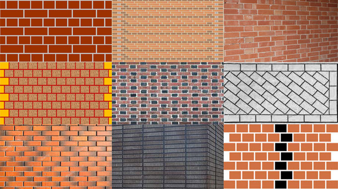
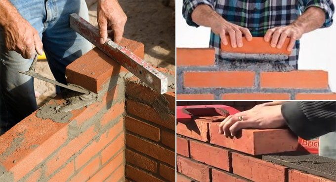
A brick bond belongs to a pattern where the bricks are placed. The applications of brick bonds are found on the walls as well as for brick paving for paths & patios, concrete blocks and different types of masonry construction.
Brick Bonds can improve the strength & stability of the structure, retain consistency to the structure and composition, and increase the visual appeal. Given below, the details of commonly used wall brick bonds :-
1. Stretcher Bond / Running Bond: It is also known as running bonds. The process is very simple to place this type of bond. Stretcher bond is useful when the walls of half brick thickness are required to be constructed. This bond is applied to build up several types of wall construction as follows :
• Sleeper walls
• Partition walls
• Division walls (internal dividers)
• Chimney stacks
Stretcher bonds should not be used for self-sustaining structural walls, but it is effective for building up the walls of less thickness. Remember, this bond can collapse when the thickness of the walls remains greater than half of the total length of the brick applied.
2. Header Bond: A header stands for the shorter face of the brick. In header bond brick masonry, all the bricks are built up in the header course. Under this type of bond, the overlap is done according to a half width of the bricks. The three-quarter brickbats are used as quoins in alternative courses. This bond is primarily applied for the erection of one brick thick walls.
3. English Bond: This bond contains alternating courses of headers and stretchers. Headers are placed in center position on the stretchers in the course underneath and each alternate row is arranged vertically. To rupture the continuity of vertical joints, a quoin closer is utilized at the start and end of a wall once the first header is provided.
A quoin close belongs to a brick that is cut into 2 halves according to length and applied to the corners in brick walls. This type of bond is useful for building up strong one brick thickness walls.
4. Flemish Bond: Under this type of bond, alternate headers and stretchers are contained in each course. Each header remains on the center of a stretcher over and below and each alternate course is started with a header in the corner. To rupture the vertical joints in the sequential courses, quoin closers are provided with alternate courses alongside the header.
5. Stack Bond: In a stack bond, all the bricks are simply loaded on top of each other and retained with mortar where all bonds are arranged properly. Due to its poor masonry structure and less strength, stack bonds are effective for decorative purposes.
As this bond is a non-structural bond, therefore it should not be used for the walls which need to transmit loads.
6. Dutch Bond: It is a customized form of the English cross bond that includes alternate courses of headers and stretchers. In this arrangement of the brick bond, each single stretching course is started at a quoin containing a 3-quarter bat. Each alternate stretching course contains a header set alongside the 3-quarter bat brick placed at the quoin. This bond is suitable for developing strong corners of the wall that is susceptible to extra loads.
7. Common Bond / American Bond: This bond contains courses of headers provided with each five or six courses. Header courses are placed in center position of the previous header course. This header bond usually functions as a tie brick among the fronting and the backing. To attain the plenty offset in a standard common bond, queen closers are provided at both ends of the header courses. The common bond is generally applied in outside load-bearing walls.
8. Facing Bond: This bond is effective for thick walls, where the facing and backing are selected for construction with bricks having different thickness. Normally, this bond comprises of heading and stretching courses which are provided in such way that one heading course comes after quite a lot of stretching courses. The load distribution of walls of this bond is irregular due to the variation among the facing and the total number of joints in the backing. It can also result in unequal settlement of the 2 thickness of the wall.
9. Diagonal Bond: It is perfect for walls with two to four brick thickness. This bond is generally provided at each 5th or 7th course along the height of the wall. Bricks in this bond are arranged end to end in such a way that extreme corners of the sequence gets in touch with the stretchers.
10. Rat Trap Bond: Under this bond, bricks are placed on edge or in a vertical location rather than the conventional horizontal position. It produces a cavity (hollow space) inside the wall as a result superior thermal comfort is maintained and the inside becomes cool as compared to the outside and vice versa. Because of the internal cavity, a little amount of materials is required for this type of walls.
Brick Bonds Types And Patterns

~~~~~~~~~~~~~~~~~~~~~~~~
Published By
Rajib Dey
www.constructioncost.co
~~~~~~~~~~~~~~~~~~~~~~~~

Friday, June 28, 2019

Details about Ultrasonic Pulse Velocity

This test is conducted for the purpose of evaluating the concrete quality with ultrasonic pulse velocity method with adherence to IS: 13311 (Part 1) – 1992. The underlying principle of this test is –
Under this method, testing is done by sending an ultrasonic pulse through the concrete and time of movement is calculated. Relatively, greater velocity exists if the quality of concrete is good with respect to density, consistency, homogeneity etc.
The following method is applied to ascertain the strength of hardened concrete with Ultrasonic Pulse Velocity :-
i) Making it ready for use: Prior to changing to the ‘V’ meter, the transducers should be attached to the sockets leveled as “TRAN” and ” REC”.
The ‘V’ meter is activated with either: a) the internal battery, b) an external battery or c) the A.C line.
ii) Set reference: A reference bar is arranged to examine the instrument zero. The pulse time for the bar is inscribed on it. Prior to set it on the opposite ends of the bar, provide a coat of grease to the transducer faces. Fine-tune the ‘SET REF’ control unless the transit time of reference bar is captured on the instrument read-out.
iii) Range selection: For greater precision, it is suggested that the 0.1 microsecond range should be chosen for path length upto 400mm.
iv) Pulse velocity: After detecting the exact test points on the material to be tested, thorough measurement of the path length ‘L’ should be done. Provide couplant to the surfaces of the transducers and press it firmly onto the surface of the material.
It is suggested not to shift the transducers at the time of taking a reading since noise signals and errors in measurements may occur. Keep on retaining the transducers onto the surface of the material unless a reliable reading is shown on the display that is the time in microsecond for the ultrasonic pulse to pass through the distance ‘L’. The mean value of the display readings should be captured while the units digit follows among two values.
Pulse velocity=(Path length/Travel time)
v) Partition of transducer leads: It is recommended to avoid the two transducer leads from getting in touch with each other at the time of taking the transit time measurements.
If it is not performed, the receiver lead will pick-up unnecessary signals from the transmitter lead and it leads to an wrong display of the transit time.
Interpretation of Results
The quality of concrete with regard to consistency, occurrence or nonexistence of internal faults, cracks and segregation, etc, indication of the level of workmanship provided, can thus be examined with the following guidelines which are changed for defining the quality of concrete in structures with regard to the ultrasonic pulse velocity.
Details about Ultrasonic Pulse Velocity

~~~~~~~~~~~~~~~~~~~~~~~~
Published By
Rajib Dey
www.constructioncost.co
~~~~~~~~~~~~~~~~~~~~~~~~

Thursday, June 27, 2019

Major responsibilities of a contractor in construction project

In this civil engineering article, you will get the details about the role of a contractor and the liabilities of him.

Normally, a contractor has to plan, implement, supervise, examine and direct a building construction project from beginning to completion devoid of the scope of the project. The contractor verifies that the project abides by all the specifications as provided in the contract documents.

1. Role Of A Contractor In Project Planning

The project management team develops a master schedule for the project depending on the completion date of the project.

To finish the project on scheduled time according to master schedule, the contractor has to take the following responsibilities :

• Plan for all the important project development and execution details beforehand.
• Specify and evaluate different project issues like the necessary materials, equipment, and personal requirements.
• Anticipate any probable changes.
• Execution of a trustworthy communication strategy between all concerned stakeholders.
• Focus on all legal and regulatory issues and requirements.
• Draft an efficient safety policy.

2. Role Of A Contractor In Project Management

Since the contractor is responsible to finish the project on scheduled time, he should bear the following responsibilities in project management.

• Making funds to accomplish construction tasks.
• Organize the materials for different tasks as projected.
• Arrange necessary construction equipments.
• Appoint required subcontractors to finish the job.
• Submit bills for the completed tasks as mentioned in the contract.

3. Role Of A Contractor In Project Monitoring

To finish the project according to specifications and minimize different issues in the project, a contractor has to take a vital role in project monitoring. He has to perform the following key responsibilities in this field.

• Track time schedule.
• Apply cost-effective methods.
• Check work quality.
• Execution of materials management system.
• Monitor problems associated with safety.

4. Role Of A Contractor In Legal And Regulatory Issues

The contractor also plays an important role in legal and regulatory issues. Besides, he has to check that the project isn’t breaching any legal terms.

• Ensure that the project is in accordance with all the required legal and regulatory issues.
• Obtaining all the required permits prior to progressing with the project.
• Paying or making sure to disburse all the fees and taxes essential to finish the project.

5. Role Of A Contractor In Health And Safety Issues

The contractor has to undertake the following liabilities for health and safety issues.

• Maintain health and safety in the workplace.
• Execute a safety method and standards for the project.
• Apply the proper safety equipment in the project.
• Execution of well organized risk management and communication strategies.
• Provide safety awareness among workers.

Read more

Major responsibilities of a contractor in construction project

~~~~~~~~~~~~~~~~~~~~~~~~
Published By
Rajib Dey
www.constructioncost.co
~~~~~~~~~~~~~~~~~~~~~~~~

Wednesday, June 26, 2019

How to measure concrete mix design

Concrete mix design refers to the method utilized for finding out the exact ratios of cement, sand and aggregates for concrete so that the target strength of concrete can be obtained.
For concrete mix design, different types of laboratory testing and calculations should be accomplished to get exact mix ratios. This method is suitable for Building structures where superior grades of concrete are required like M 25 and over as well as large construction projects where quantity of concrete consumption is extreme.
The main objective of concrete mix design is to arrange the proper ratios of materials so that the application of concrete becomes cost-effective to maintain perfect strength of structural members. In a project, large quantity of concrete & construction work are required and saving in quantity of materials like cement makes the construction project cost-effective.
Concrete Mix design of M – 20, M – 25, M – 30 and superior grade of concrete are measured from following steps:
Concrete Mix Design:
Necessary data for Mix Design of Concrete:
• Concrete Mix Design Date:-
(a) Characteristic compressive strength of concrete necessary at end of 28 days = M 25
(b) Nominal maximum size of aggregate applied = 20 mm
(c) Shape of Coarse Aggregate = Angular
(d) Necessary workability at site = 50-75 mm (slump Value)
(e) Quality control is performed as per IS: 456
(f) Type of exposure condition of concrete (as specified in IS: 456) = Mild
(g) Type of cement applied = PSC as per IS: 456 – 2000
(h) Method of providing Concrete on Site = pumpable concrete
(ii) Material testing data (set in the laboratory):
(a) Specific gravity of cement = 3.15
(b) Specific gravity of FA = 2.64
(c) Specific gravity of CA = 2.84
(d) The surface of aggregates is supposed to be in dry condition.
(e) Fine aggregates are abided by Zone II of IS – 383
To get details on the method of M-25 grade concrete mix design, click on the following link. civiconcepts.com
How to measure concrete mix design

~~~~~~~~~~~~~~~~~~~~~~~~
Published By
Rajib Dey
www.constructioncost.co
~~~~~~~~~~~~~~~~~~~~~~~~

Tuesday, June 25, 2019

Methods of concrete cube test

In concrete compression test, generally the concrete cube samples with dimensions 150mmx150mmx150mm are utilized. But, in place of 150mmx150mmx150mm concrete cube samples, 100mmx100mmx100mm concrete cube samples are applied for the test.

Fundamentally, the force produced through a concrete compression machine is a definite value. For the use of normal concrete strength, suppose under 50MPa, the stress provided by a 150mmx150mmx150mm cube is adequate for the machine to smash the concrete sample.

However, when the intended concrete strength is 100MPa, under the equivalent force (about2,000kN) delivered by the machine, the stress under a 150mmx150mmx150mm cube is inadequate to crush the concrete cube.

So, 100mmx100mmx100mm concrete cubes are used in place of 150mmx150mmx150mm cubes to raise the used stress to crush the concrete cubes. For normal concrete strength, the cube size of 150mmx150mmx150mm is already sufficient for the crushing strength of the machine.

Cube Test:

Instrument And Material.

Concrete cube mould with size 150mm or 100mm is applied for aggregate size of not more than 40mm and 25mm. Cube mould for test should be formed into steel or cast iron containing smooth inner surface. Each mould should contain steel plate to support and avoid leakage.

Compacting steel rod should be used with 16mm diameter and 600mm length.

The test should be conducted by compression test machine.

Method: Mould and base plate should be cleansed and employed with oil so that the concrete can’t fix to the side of the cube. Base plate is affixed to the mould with bolt and nut.
The cube should be filled with concrete in three layers.

Each layer should be consolidated for 25 times. This process should be accomplished systematically and compaction should be finished equally to all the surfaces of the concrete. Compaction is also done with machine.

The surface of concrete should be leveled to retain the equivalent level with the upper side of the mould.

Cubes which are produced at construction site should be wrapped with plastic cover for a period of 24 hours prior to remove the moulds.

After remoulded, the concrete cubes should be drowned in water for curing.
Compression strength test should be conducted for concrete at age 7, 14, and 28 days through compression test machine.

Result: The Strength value of each cube should be noted and compared with the targeted strength value. The reason for conducting the concrete test on 7 th day and the 14 th day is to anticipate whether the concrete could attain the targeted 28 th day strength. Normally, concrete can obtain 70% strength on the 7 th day.


Methods of concrete cube test

~~~~~~~~~~~~~~~~~~~~~~~~
Published By
Rajib Dey
www.constructioncost.co
~~~~~~~~~~~~~~~~~~~~~~~~

Monday, June 24, 2019

Definition of building substructure and its constituents

The primary constituents of a building substructure belong to the foundation and plinth beam. These components securely transmits the load from the superstructure to the ground.
Foundation: The foundation means the structure situated under the ground level that gets in touch with the superstructure directly. The foundation transmits the dead loads, live loads and all other loads operating on it to the foundational soil.
The construction process of foundation is done in such a manner that the soil over which it stands is stressed inside its safe bearing strength. Any failure of foundation leads to the failure of the building structure.
Therefore, different building structure requires various types of foundations like shallow or deep foundations.
Preliminary, the soil profile is checked with a geotechnical engineer prior to complete a proper foundation for the building structure. The following types of foundation are normally utilized for building structure:
1. Strip Foundation (Shallow Foundation)
2. Raft Foundation (Shallow Foundation)
3. Pile Foundation (Deep Foundation)
1. Strip Foundation: Strip foundation or strip footing offers support for linear structures like a wall or tightly spanned column, in the shape of strips. It is suitable for the soils having strong bearing strength as well as ability to support light structural loading. The size and location of the strip foundation are based on the width of the wall.
2. Raft Foundation: Raft foundation is also known as a mat foundation. It expands over the total building area and combats severe structural loads.
A raft foundation transmits the total load from the building area to the total floor area. As a result, the stress operating on the soil is significantly decreased that results in lessening the scope for shear failure of soil.
3. Pile Foundation: Pile Foundation stands for a type of deep foundation that transmits heavy loads from the superstructure to hard strata underneath the ground. Pile in a pile foundation refers to a deep reinforced concrete column that meets the hard rock strata far below the ground.
Plinth Beam: Plinth beam belongs to a beam that is developed in the plinth level among the wall and the foundation.
The purpose of this type of reinforced concrete beam is to resist the circulation of cracks from the foundation to the walls.
A plinth beam can allocate the load uniformly from the walls to the foundation. These are essential for construction projects planned in the areas susceptible to earthquake.
Definition of building substructure and its constituents

~~~~~~~~~~~~~~~~~~~~~~~~
Published By
Rajib Dey
www.constructioncost.co
~~~~~~~~~~~~~~~~~~~~~~~~

Saturday, June 22, 2019

How to create exact building plan for a G+1 storey building

In this exclusive civil engineering video tutorial, you will get some vital information on how to develop perfect building plan for any G+1 story building. Besides, you will also get details about section, elevation and 3D model.
The area of the building = 14.9 x 14.5 square meter. The building contains space for car parking, hall room, one bed room, kitchen & dining, bathroom as well as staircase.
The buildings should have firmly interconnected beams and columns which are known as building frames.
The loads from walls and beams are transmitted to beams and consequently rotation of beams occurs. As beams are firmly attached with column, the rotation of column also occurs. Therefore, any load enforced to anywhere on beam is distributed by entire network of beam and columns.
The building design involves the following steps :-
Step 1: Plan the fairly accurate layout of the building.
Step 2: Workout dead and snow load.
Step 3: Design steel roof decks:
Step 4: Choose open web steel joists
Step 5: Design beam.
Step 6: Design column.
Step 7: Design steel column bore plates.
Step 8: Design footing
Step 9: Create engineering drawing.
Step 10: Final check and submission.
To get more detail, go through the following video tutorial.
How to create exact building plan for a G+1 storey building

~~~~~~~~~~~~~~~~~~~~~~~~
Published By
Rajib Dey
www.constructioncost.co
~~~~~~~~~~~~~~~~~~~~~~~~

Friday, June 21, 2019

Different types of concrete admixtures

Instantly before or during mixing concrete, the admixture should be added to the batch of concrete to make the quality of concrete manageability, acceleration, or retardation of setting time better. Now-a-days, several concrete mixes comprise of one or more concrete admixtures that will aid in reducing the cost of pouring method as well as growing the productivity, The cost of these admixtures will differ on the basis of the quantity and type of admixture to be applied. All of these will be added to the cubic yard/meter cost of concrete.
Given below, the details about the different types of concrete admixtures :-
Concrete Admixtures: Set-Retarding: The purpose of set retarding concrete admixtures is to defer the chemical reaction that occurs when the setting process is initiated for concrete. These types of concrete admixtures are generally applied to minimize the impact of high temperatures that can expedite the initial setting of concrete.
Set retarding admixtures are mostly found in concrete pavement construction. They provide sufficient time for finishing concrete pavements, lessen extra costs to arrange a new concrete batch plant on the job site and facilitate removing cold joints in concrete. Retarders are also useful for withstanding cracking due to form deflection that can happen when horizontal slabs are arranged in sections. Most retarders also perform as water reducers and may entail some air in concrete.
Concrete Admixtures - Air-Entrainment: With air entrained concrete, the freeze-thaw strength of concrete is raised significantly. This type of admixture develops a more executable concrete as compared to non-entrained concrete and at the same time the bleeding and segregation of fresh concrete is minimized. Besides, resistance strength of concrete against extreme frost action or freeze/thaw cycles is considerably improved. This admixture provides the following advantages:
• Greater resistance against cycles of wetting and drying
• Superior degree of workability
• Superior degree of stability
The entrained air bubbles function as a physical buffer against the cracking resulting from the stresses owing to water volume augmentation in freezing temperatures. Air entrained admixtures are well suited with almost all the concrete admixtures. Normally, for each one percent of entrained air, compressive strength will be decreased by about five percent.
Water-Reducing Concrete Admixtures: Water-reducing admixtures belong to chemical products which can be added to concrete for producing a required slump at a lower water-cement ratio than what it is generally designed. The purpose of water-reducing admixtures is to retain certain concrete strength with lower cement content. Lower cement contents lead to lesser CO2 secretions and energy consumption per volume of concrete created.
This type of admixture facilitates to enhance the properties of concrete as well as set concrete under tough situations. Water reducers are mainly utilized in bridge decks, low-slump concrete overlays, and patching concrete. Now-a-days, mid-range water reducers are gaining popularity because of the improvements in admixture technology.
Concrete Admixtures - Accelerating: Accelerating concrete admixtures are applied to accelerate the rate of concrete strength formation as well as minimize the setting time of concrete. Calcium chloride is the example of common accelerator component though it may develop the scope of erosion in steel reinforcement. Accelerating admixtures are suitable for altering the properties of concrete in cold weather.
To get more details, click on the following link www.thebalancesmb.com
Different types of concrete admixtures

~~~~~~~~~~~~~~~~~~~~~~~~
Published By
Rajib Dey
www.constructioncost.co
~~~~~~~~~~~~~~~~~~~~~~~~

Thursday, June 20, 2019

Causes of honeycombing in concrete and proper solutions

Honeycombing refers to a structural defect related to a RCC Structure. The areas of the concrete surface where the coarse aggregate are clearly shown known as honeycombed surface that provides an appearance of honey bees nest.

If honeycombed surface is ignored, the RCC structure fails to function properly according to the design (structurally fragile). Besides, it enables penetration of damaging agents like impure water and air through the existing voids which impact the stability of the structure considerably.

Honeycombing happens for the following reasons :-

1. Concrete mix does not remain integral.
2. Existence of more percentage of larger size of aggregate in concrete resists concrete to fill narrow spaces among the reinforcement rods.
3. The workability of concrete is inadequate.
4. Inadequate compaction to concrete.
5. Imperfect vibration throughout concreting.
6. Steel congestion does not permit concrete to flow toward all corner.
7. Concrete is already set prior to placing.
8. High free fall of concrete at the time of pouring

9. Form work is not water-resistant or inflexible.
10. Inappropriate detailing and/or fixing of steel
11. Inferior proportion of cement to water that can minimize the workability of concrete.


Guidelines to get rid of Honeycombing in Concrete.

All concrete batches should be integrated; examine the concrete production/cohesiveness frequently. If it is possible to develop “ball” form the fresh concrete, concrete mix is defined as cohesive.
 
Concrete workability should meet the placement requirement, as for instance, a lightly reinforced column can contain 75mm slump, 150 mm slump is necessary for a highly reinforced column.

Make sure that exact compaction is provided for placed concrete, vibrators should be detached since large air bubbles stop to step out (over vibration will cause bleeding). The sizes of the vibrator needle should remain as 25 mm, 40 mm and 60 mm according to RCC sections.

Concrete should be exhaustively consolidated and fully functional around the reinforcement, around implanted fixtures as well as the corners of the formwork. Precautions should be taken throughout vibration otherwise honey combing may occur.

The strength of concrete is decreased by 30% due to 5% voids in concrete.

Cover to formwork, Pins and spaces bars to layers of reinforcement should be provided to maintain exact compaction.

Concrete should maintain Slump prior to placing. Besides, initial slump, concrete should be designed to detain slump untill the time it is set.

The height from where the concrete is dropped should be minimum, if possible concrete bucket with canvas pipes, concrete hose pipe, should be provided to minimize the concrete free fall height.

Formwork should be water resistant; cement grout should not be wasted at the time of placing concrete.

Steel detailing and fixing should be provided to allow smooth flow of concrete across all corners and depths. To get rid of steel congestion, special concrete formulations like self-compacting concrete, concrete with lower maximum aggregate size (12.5mm) etc should be used.

Read more

Causes of honeycombing in concrete and proper solutions

~~~~~~~~~~~~~~~~~~~~~~~~
Published By
Rajib Dey
www.constructioncost.co
~~~~~~~~~~~~~~~~~~~~~~~~

Wednesday, June 19, 2019

ACI 318-14 approved design guidelines of isolated footing

Isolated alias single footing is utilized to provide support to single RCC columns. It is cost-effective and suitable when the columns are placed at comparatively long distances, loads operating on footings are less and the safe bearing strength of the soil usually remains high.

Isolated footing is categorized as pad footing and sloped footing.

The isolated footing is arranged underneath the column to disperse the loads securely to the bed soil.

The design of isolated footing is made for the following purposes :-

Area of footing

Thickness of footing

Reinforcement details of footing with a satisfactory moment and shear force review.
The design of isolated footing is made on the basis of the guidelines set by ACI 318-14.

1. The compressive strength of concrete should satisfy the needs for both strength and stability. As per ACI 318-14, least concrete compressive strength should be 17MPa for normal applications.

2. With adherence to ACI 314-14 section 20.2.1.1, the deformed type steel bars should be used.

3. Factored forces and moments provided at the base of columns are transmitted to the foundation with reinforcement, dowels, anchor bolts, or mechanical connectors.

4. There should be least reinforcement even if the concrete bearing strength is not crossed.

5. Adequate anchorage should be arranged for tension reinforcement if reinforcement stress is not directly relative to the moment like in sloped, stepped or tapered foundation.

6. There should be sufficient anchorage length of both flexural and dowel reinforcement to get rid of bond failure of the dowels in the footing and to resist failure of the lap splices among the dowels and the column bars.

7. As per ACI 318-14 section 13.3, depth of footing over reinforcement should not remain under 150 mm.

8. The depth of the footing should be in such a manner that the shear strength of the concrete remains equivalent or surpasses the critical shear forces (one-way shear and punching shear) developed with factored loads.

9. In sloped, stepped, or tapered foundation, location and depth steps and angle of slope should satisfy design requirements at each section.

10. Concrete cover of 75 mm is necessary when the concrete is cast against soil.

11. With adherence to ACI Code specifications, base area of footing is set from unfactored forces and moments transferred by footing to soil and the permissible soil pressure evaluated through principles of soil mechanics. To get the necessary base area of the footing, the column service loads are divided with permissible net soil pressure of the soil. The net factored soil pressure is equivalent to factored load column loads by the selected footing area.

Read more

ACI 318-14 approved design guidelines of isolated footing

~~~~~~~~~~~~~~~~~~~~~~~~
Published By
Rajib Dey
www.constructioncost.co
~~~~~~~~~~~~~~~~~~~~~~~~

Tuesday, June 18, 2019

Some useful notes on Pile Cap Design

Definition of Pile Cap: A pile cap refers to a thick concrete mat that is situated on concrete or timber piles driven into soft or unsteady ground to develop a proper & secure foundation. It normally builds up section of the foundation of a building, mostly a multi-story building, structure or support base for heavy equipment.

It is frequently found that one pile can’t bear the entire load enforced on the column. Therefore, the column requires over one pile to bear the load. Here, a pile cap plays an important role to disperse the column load to these piles uniformly.

In this stage of design, precautions should be undertaken to disperse the load to the piles evenly by placing the center of gravity of the column to match up with the center of gravity of the pile cap.

To make sure that the load is transmitted from the column to the pile, the pile steel reinforcement should be expanded inside the pile cap with minimum 600 mm so that the load is transmitted with the bond among concrete and steel.

The pile caps are designed as a rigid foundation and ensure that the piles bear equivalent loads from the column in order that the pile cape thickness should be designed to withstand the punching stresses and the tension in top and bottom.

Shape and Size of Pile Caps:

1. The shape and plan dimensions of the pile cap are based on the number of piles in the group and the gapping among each pile.
2. These pile caps outlines & minimizes the plan area for uniform arrangement of piles about the load.
3. The pile cap should overlap exterior piles by minimum 150mm but should not be too much, usually not in excess of the diameter of the pile diameter.


It reduces the plan area as well as the cost, at the time of arranging adequate length to the followings:

1. Affix the tension reinforcement with a large radius bend
2. Provide sufficient cover to the reinforcement
3. Meet the tolerances of the construction


Depth of Pile Cap - The depth of pile cap is influenced by the following factors :

1. Shear strength of pile cap (beam and punching shear)
2. Shrinkage and swelling of clay


3. Frost attacks
4. Pile anchorage
5. Water table and soluble sulphates
6. Maintain bolt assemblies for steel columns


Shear is considered as most important factor for selection of depth of pile cap.

Normally a pile cap is much deeper as compared to a pad footing having similar dimensions, since it is prone to greater concentrated reactions, and accordingly to much greater bending moments and shear forces.

However, the increased depth assigns greater rigidity to the pile cap that results in spreading the load uniformly to all piles.

Some useful notes on Pile Cap Design

Read more
~~~~~~~~~~~~~~~~~~~~~~~~
Published By
Rajib Dey
www.constructioncost.co
~~~~~~~~~~~~~~~~~~~~~~~~

Monday, June 17, 2019

Details about soil mechanics

This civil engineering article is based on soil mechanics. The article focuses on soil development, source of transportation of soil, normally found soil designation, soil structure etc.

How soil is developed?

1. The soil is categorized as organic or inorganic depending on the geological source.
2. As organic soils very compressible, they should not be used as a foundation material.
3. Organic soils are also known as cumulose soil. Examples of organic soils are peat muck and humus.
4. To develop inorganic soils, the rocks are seasoned because of mechanical decay or chemical degradation.
5. Physical decomposition or mechanical weathering happens because of the impact of temperature variations.
6. Because of physical decomposition, chemical composition of soil remains unchanged.

7. Course grained soils like IS gravel and sand are built up with the method of physical decomposition.
8. Chemical disintegration or chemical weathering of rocks happens owing to hydration, carbonation, oxidation, solution and hydrolysis.
9. Because of chemical disintegration, original materials are changed to new materials through chemical reactions.
10. Chemical degradation of rocks leads to development of clay minerals.
11. Soils are made with geologic cycle that runs uninterruptedly in nature.

 
The geological cycle contains corrosion, transportation, deposition and upheaval of soil.

Normally applied soil designation:

Bentonite : Disintegrated volcanic ash in which high percentage of clay mineral (montmorillonite) are included.

Black Cotton Soil : It contains the mineral montmorillonite and discharge large swelling and shrinkage.

Loam : It is formed by mixing sand, silt and clay size particles approximately in same ratios.

Moorum : It belongs to gravel blended with red clay.

Varved clay : It belongs to clay and silt of glacial origin particularly a lacustrine deposited.

Go through the following video for online demonstration www.youtube.com

Details about soil mechanics

~~~~~~~~~~~~~~~~~~~~~~~~
Published By
Rajib Dey
www.constructioncost.co
~~~~~~~~~~~~~~~~~~~~~~~~

Friday, June 14, 2019

Impacts of earthquake on structures

Earthquake produces severe damages to the structures. For this purpose, thorough knowledge about the seismic effects on a structure is required. The designers and contractors should be capable of analyzing the effect of seismic forces on buildings to adopt protective measures against failures and collapses.

When earthquake strikes on structures, it develops damaging inertia forces which lead to deformations as well as horizontal and vertical shaking.

Given below, detail explanation about these effects :-

Impacts of Earthquake on Structures

1. Inertia Forces in Structures: The formation of inertia forces in a structure refers to one of the seismic influences that adversely damage the structure. When ground shaking occurs due to earthquake, the base of the building proceeds but the roof remains motionless. As the walls and columns are connected with it, the roof is pulled by the base of the building.

The susceptibility of the roof structure to stand at its original position is known as inertia. The inertia forces lead to shearing of the structure that can consolidate stresses on the fragile walls or joints in the structure causing failure or perhaps total collapse. Lastly, more mass signifies greater inertia force and due to this lighter buildings can resist the earthquake shaking efficiently.

2. Impact of Deformations in Structures: When a building undergoes earthquake along with ground shaking, the base of the building proceeds with the ground shaking. But, the roof movement varies from that of the base of the structure. This variation in the movement produces internal forces in columns and as a result the column goes back to its original position.

These internal forces are known as stiffness forces. The stiffness forces become greater when the sizes of columns are raised. The stiffness force in a column belongs to the column stiffness times the relative displacement among its ends.

3. Horizontal and Vertical Shaking: Earthquake contributes to shaking of the ground in all the three directions X, Y and Z, and the ground shakes indiscriminately from side to side along each of these axis directions. Normally, the purpose of designing the structures is to resist the vertical loads in order that the vertical shaking resulting from earthquakes (either adds or subtracts vertical loads) is controlled through safety factors provided in the design to sustain vertical loads.

However, horizontal shaking along X and Y directions is dangerous for the operation of the structure as it develops inertia forces and lateral displacement and consequently sufficient load transfer path should be arranged to resist its detrimental influences on the structure.

Exact inertia force transfer path is formed through adequate design of floor slab, walls or columns, and connections among these structural components. It should be noted that the walls and columns are vital structural components in transmitting the inertial forces. The masonry walls and thin reinforce concrete columns create weak points in the inertia force transfer path.

4. Other Effects: Due to earthquake various other effects may occur which range from liquefaction, tsunami, and landslides. These belong to the indirect effects of strong earthquakes that can lead to significant devastation.

Read more

Impacts of earthquake on structures

~~~~~~~~~~~~~~~~~~~~~~~~
Published By
Rajib Dey
www.constructioncost.co
~~~~~~~~~~~~~~~~~~~~~~~~

Thursday, June 13, 2019

How to work out the rolling margin for reinforced steel

Rolling margin means the proportion of deviation in permissible sectional weight of reinforcement steel according to IS codes. Reinforcement steel is ejected from a mould that is formed with a specific size e.g. 8mm Dia. When the mould is completely new, the sectional weight of 8mm steel ejected via mould will remain lower than that .i.e. 0.395kg per Metre or lessor according to IS codes.

Mould will be expanded in due course of time or once specific quantity of production is extracted from a specific mould.

Now, similar 8mm dia bars are ejected from the equivalent mould and they will gain more weight per Metre, as for example 0.400Kg per Metre rather than 0.395 as per IS. It sinifies more mass per Metre/Length is necessary for same length.

This deviation in weight as per IS code-1786 for several dia is given below :-

8mm to 10mm +- 7%
12mm to 16mm +- 5%.
20mm and above +- 3%.


The measurement of rolling margin is done in the following ways :-

Total Weight of Bars (Dia wise) / Total Running Metre of Bars = Actual Sectional Weight of bars.

Compare sectional weight with Standard IS Weight.

Weight as per IS Standard = Dia x Dia / 162.
 
Rolling margin is the variation among the theoretical and actual weight of steel. It is caused by the die utilized for casting of rebars. As time goes, the shape of die is modified and consequently the diameter of the steel bar is also altered that leads to disparity in unit weight of steel.

The size of the die is retained small and accordingly rolling margin is negative in the preliminary phase of production, after that it is more of less near to theoretical weight and then the size of die is raised that causes to put rolling margin on positive side.

If the steel is brought from similar supplier over a period of time the rolling margin would be revised and no loss will be occurred.

How to work out the rolling margin for reinforced steel

Read more
~~~~~~~~~~~~~~~~~~~~~~~~
Published By
Rajib Dey
www.constructioncost.co
~~~~~~~~~~~~~~~~~~~~~~~~

Wednesday, June 12, 2019

Some vital instructions to make your boundary walls stronger

Substandard foundations, poor design, scarcity of expansion joints and piers (support pillars) generally lead to cracks in masonry boundary walls.

If a subsisting wall is inclined, unsteady or contains severe cracks, then proper remedies should be taken immediately.

Given below, some vital guidelines while setting up a new boundary wall:

1. The design of the wall: Besides, adhering to local by-laws concerning height restrictions and set-backs on street corners, proper engineering principles should also be applied to the design of any freestanding wall.

Both the thickness of the wall and the spacing of piers control the maximum height of the wall over ground level.

2. Foundations: While creating the design of the foundations, soil conditions and slopes should be considered. Steel reinforcement of the foundations and of the wall itself are vital components. A general rule of thumb is that the foundation should be broader and deeper so that the support of the wall becomes more stable.

3. Retaining walls: When the boundary wall functions as a retaining wall and is susceptible to water and soil thrust, then the foundation footing should be expanded more beneath the upper side of the wall to make sure that the weight of the chosen soil further firm ups the foundation structure.

4. Adequate expansion joints and piers: If expansion joints are not set up perfectly without adequate piers, the walls can be cracked easily.

If there are cavities in the piers of freestanding walls (along with hollow units), they should be filled with concrete instantly.

5. Drainage: If the boundary wall is located on a slope, then sufficient weep holes should be installed to dispose of accumulated storm water.

When the wall also functions as a retaining wall, there should proper arrangement of sub-soil drainage. NHBRC (Part 3. 3:24) indicates that weep holes should be set up in all retaining walls at a height not greater than 300mm over the lower ground level at centres not surpassing1.5 metres. Weep holes should be created with a 50mm plastic pipe covered on the non-exposed end with a geofabric.

6. Damp: Boundary walls are generally freestanding as these walls do not usually build section of a structure (like a house), where the connected walls are self-bracing. Since the freestanding walls are not supported by a structure of other walls, boundary walls are normally constructed exclusive of a damp proof course (DPC), plastic membrane so as to make the bond stronger among the freestanding wall and its foundation.

A DPC can rupture the bond among wall and foundation that leads to instability. Without DPC, mounting damp is frequently found on plastered and painted boundary walls. To get rid of this issue, the harder (less porous) bricks should be used for the lower courses (first 150mm) and make sure that the plaster does not expand to the level of the soil, else the plaster will function as a wick and allow water going from the ground to wick upwards.


Some vital instructions to make your boundary walls stronger

~~~~~~~~~~~~~~~~~~~~~~~~
Published By
Rajib Dey
www.constructioncost.co
~~~~~~~~~~~~~~~~~~~~~~~~

Tuesday, June 11, 2019

Common Defects In Plastering

Several types of defects are found in plastering work which range from blistering, cracks, efflorescence, flaking, peeling, popping, softness and uneven surfaces. When these defects are visible, they should be repaired instantly.
Types of Defects in Plastering :-
1. Blistering of Plastered Surface: Blistering of the plastered surface is happened when small patches are expanded outside the plane of the plastered surface. Blistering is visible for plastered surface inside the building.
2. Cracks in Plastering: Cracks are developed on the plastered surface. Two types of cracks are found i.e. hairline cracks and wider cracks. The hairline cracks can’t be seen easily whereas the wider cracks are observed easily. The formation of fine cracks is termed as crazing.
Cracks on a plastered surface occur because of thermal movements, discontinuation of surface, structural defects in the building, defective workmanship, too much shrinkage etc.
3. Efflorescence on Plastered Surface: Efflorescence is developed on plasters when soluble salts are found in plaster making materials and building materials like bricks, sand, cement etc. Even water applied in the construction work may include soluble salts.
When a wall (newly built up) dries out, the soluble salts are provided to the surface and they become visible in the form of a whitish crystalline substance. Such a growth is defined as efflorescence and the adhesion of paint with the wall surface is severely damaged with it.
Efflorescence provides a very ugly appearance and can be eliminated slightly through dry-bushing and washing the surface frequently.
4. Flaking: The development of a very small loose mass on the plastered surface is called flaking and it is mainly occurs because of bond failure among consecutive coats of plaster.
5. Peeling: In peeling, the plaster from some section of the surface are detached and a patch is developed. Peeling is primarily occurred because of bond failure among successive coats of plaster.
6. Popping: Sometimes the plaster mix comprises of particles which get bigger on being set. A conical hole in plastered surface is created in front of the particle. This conical hole is termed as blow or pop.
7. Irregular Plaster Surface: Irregular surface defect becomes apparent because of substandard workmanship of the plastering work.
8. Softness of the Plaster: The extreme dampness at specific points on the plastered surface transforms that section soft. The softness mainly happens owing to unnecessary thinness of the finishing coats, existence of deliquescent salts, extreme suction of the undercoats etc.
9. Rust Stains on Plastered Surface: Rust stains are sometimes visible on the plastered surface specifically when plaster is provided on metal lath.
Common Defects In Plastering
Read more
~~~~~~~~~~~~~~~~~~~~~~~~
Published By
Rajib Dey
www.constructioncost.co
~~~~~~~~~~~~~~~~~~~~~~~~