adsense analytic

Friday, May 31, 2019

Importance of mortar in brickwork construction

In brickwork construction, different types of mortars like M1, M2 etc. are applied. Normally, lime mortar and cement mortar are frequently utilized for brickwork. The characteristics, strength and applications of these mortars are discussed below :-
Consideration should given on the following factors for Mortar in Brickwork Construction :-
1. The strength of brickwork is not affected by the grade of the mortar used, i.e. several mortar mixes of diverse grades like M1 and M2 contain dissimilar strengths, but the strength of brickwork is not compromised. As for instance, mortars of mix ratios 1:6 and 1:4 provide equivalent strength of brickwork with the similar type of bricks, while they contain different strengths. It signifies that the strength of brickwork is based on the strength of bricks.
2. If the mortar mix ratio of 1:3 is applied for cement to sand or (cement + lime) to sand ratio, a solid mortar is produced with less voids.
3. Benefits of Lime Mortar – As the strength of lime mortar is under cement mortar, inclusion of lime in mortar brings the following benefits:
• Shrinkage in mortar is fewer, thus less susceptible to cracks because of shrinkage.
• The workability and plasticity of the mortar mix is enhanced with lime.
• Lime contains superior water retention strength and does not vaporize rapidly. Besides, dry bricks can’t absorb water from the lime mortar.
• Lime raises the volume of mortar and fills the voids so that it becomes water resistant against rain infiltration.
• Lime mortar can bond with bricks efficiently.
• Cement-lime mortar is more flexible and can adjust the normal movements of brick masonry without causing cracking. So, normally, cement lime mortar less susceptible to cracking as compared to cement mortar.
4. Lime mortar attains strength gradually and contains lower ultimate strength as compared to cement mortar. Besides, lime mortar with hydraulic lime can get superior and early strength. Lime mortar with fat lime does not consolidate at all in wet locations. While applying fat lime, some pozzolanic materials like burnt clay should be utilized instead of sand to enhance the strength of mortar.
5. Cement-lime mortar of leaner mixes from ratio 1:4 to 1:8 becomes rough specifically when the sand is coarse and not graded. Consequently, plasticizers should be utilized for better workability and plasticity of the mortar.
6. The strength of cement mortar is impacted by the following factors for the same ratio of cement and sand:
a. Grading of sand
b. Fineness and coarseness of sand
c. Angularity and roundness of the sand particles
7. If fineness of sand is raised, the workability of the cement-mortar mix is also increased. On the other hand, the surface area of the sand is also increased for which requirement for cement and water quantity for the same strength is also increased.
The strength will be reduced when the cement quantity is not raised. To attain the required workability, adequate water is necessary. This condition raises the water-cement ratio and as a result the strength is decreased.
8. Curing plays an important role to attain the maximum strength as well as maximum coating of the obtainable cement around sand particles.
9. Mortar beyond a mix ratio of 1:3 should not be applied in brickwork masonry construction due to high shrinkage and no considerable increase in strength of masonry, although the strength of mortar itself raises.
10. Overly thick joints decrease the strength of the brickwork.
11. Inclusion of pozzolana enhances the strength of the mortar as well as resistance capacity against chemical attacks.
~~~~~~~~~~~~~~~~~~~~~~~~
Published By
Rajib Dey
www.constructioncost.co
~~~~~~~~~~~~~~~~~~~~~~~~


Thursday, May 30, 2019

Some vital tips for the selection of proper foundation types

In order to maintain the longevity of a building, the most vital step is to explore foundation types and select the most suitable foundation for your building project.


FOUNDATION TYPES FROM THE GROUND UP: As per the Soil Mechanics in Engineering Practice, a foundation means the lower segment of a building structure that transmits its gravity loads to the earth. This foundation is selected based on the following factors -
1. Ground/soil conditions
2. Types of loads from the building structure
GROUND/SOIL CONDITIONS - Soil investigation is performed for the following purposes :
• Nature and type of soil
• Depth of various layers of soil
• Bearing strength of the soil at different levels
• Level/slope of the ground
As for instance, when the soil adjacent to the surface does not have the capacity to sustain the structural loads, hard strata (soil layer with adequate load bearing strength) should be selected and most often deeper foundations are essential. Otherwise, with the existence of homogeneous stable ground, a shallow foundation is suitable.
LOAD TYPES FROM BUILDINGS: Loading conditions severely impact the selection of foundation types which are based on the type of building for your project, location/ecological factors and the type of structural construction materials effective for your project. The following factors are mainly responsible for raising loads and constructing deeper foundations:
• High-rise/multi-story buildings
• Susceptibility to strong winds or earthquake zones
• Reinforced concrete buildings
PUT THE PIECES TOGETHER: As soon as the soils are examined and loads types are established for the building project, then put the pieces together and opt for the best foundation type for the project. These main foundation types comprise of the following :-
• Spread/wall footings.
• This type of foundation is applicable where the base is broader as compared to a normal load bearing wall.
• The broader base allocates the weight from the building structure across a larger surface area and enhances the longevity of the building.
• Drilled pier/deep foundation.
• This type of deep foundation is useful for transmitting greater loads from the building structure to hard rock strata.
• This type of foundation can minimize the amount of ground disturbance whereas provides protection against earthquakes and wind forces. It is also suitable where highly expansive soils exist near surface.
• Post-tensioned slab foundation.
• This type of foundation extends over the entire area of the building to sustain loads from columns and walls.
• It can be utilized on expansive soils.


~~~~~~~~~~~~~~~~~~~~~~~~
Published By
Rajib Dey
www.constructioncost.co                                                                                    ~~~~~~~~~~~~~~~~~~~~~~~~

Wednesday, May 29, 2019

Calculation of water cement ratio in concrete

Definition Of Water Cement Ratio - Water Cement Ratio indicates the ratio among the weight of water to the weight of cement applied in concrete mix.
Generally water cement ratio remains under 0.4 to 0.6 according to IS Code 10262 (2009) for nominal mix (M10, M15 …. M25).
The strength of concrete is directly influenced by water cement ratio. When, the water cement ratio is perfect, the strength of concrete is raised otherwise the strength will be reduced.
Role of Water in Concrete: Concrete belongs to a macro content. It comprises of micro elements like cement, sand, fine aggregate & Coarse aggregate. To produce high strength concrete to resist necessary compressive strength, the ratio of admixture should be perfect to mix these materials.
The water can accelerate this chemical process with the addition of 23%-25% of the cement volume. Besides, it creates 15% of water cement paste defined as gel to fill up the voids in the concrete.
Impacts of excessive water in concrete: 23% of water is required to begin the chemical process on cement.
Inclusion of extra water than this permissible water cement limit will actually influence the strength.
If the process is going on to add water for enhancing the workability then the concrete contains various fluid materials where the aggregates will set. As soon as the water is vaporized it produces several voids in concrete and as a result the concrete strength is reduced.
Workability Of Concrete: Workability signifies the capacity of concrete to manage, transmit and place devoid of any segregation. The concrete becomes effective if it can be simply operated, placed and transmitted devoid of any segregation to be arranged in the job site.
Computation of Water Cement Ratio: Actually, water cement ratio is chosen from different workability test depending on the structural members, concrete strength, transportation, selection of aggregation etc.
Computation of Water Quantity for Concrete: The W/C Ratio differs from 0.4 to 0.7 on the basis of exposure conditions.
If it is required to measure the water quantity for concrete, initially determine the cement content for the volume.
Suppose, the desired cement volume is 50kg.
Required amount of water = W/C Ratio X Cement Volume
So, required amount of water = 0.5 X 50 kg = 25 litres / 50 kg cement bag.
For Design mix, the W/C ratio is based on the workability, strength requirements.
~~~~~~~~~~~~~~~~~~~~~~~~
Published By
Rajib Dey
www.constructioncost.co
~~~~~~~~~~~~~~~~~~~~~~~~

Friday, May 24, 2019

Quantity Take-off in Earthwork Volume Calculation

Quantity Take-off software is also used in calculating Earthwork Volume and this earthwork is done to restructure the topography of a site to get the design levels.

There are various types of methods of volume calculation that can be approved to find earthwork quantities; there are various civil engineering projects like road work, irrigation canal project, tank survey, earth moving, etc. for which different calculation methods are used. Some of them are invented in many time ago when the computer or calculator were not invented and still now are being used. Besides this, nowadays industry practices of various kinds of volume calculation which are discussed here to help the readers to choose the right one.

Earthworks: These are engineering works made through the moving and/or processing of huge quantities of soil and unshaped rock. Earthwork is done to restructure the topography of a site to get the design levels. Earthwork includes cutting and filling to get the needed topography.

• Cutting: It is the procedure of digging earth material from a work location or borrows pits to reach the desired topography.

It is the procedure of moving the excavated material or extra earth material to work a location to reach the desired topography.

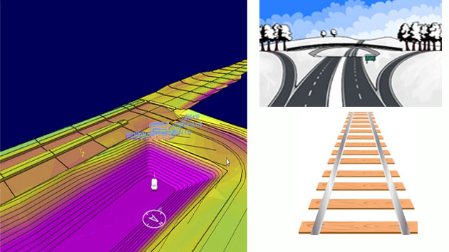
Applications of Earthwork: Earthwork is done in the projects like Road works, Railways, Irrigation project such as canals and dams, other common earthwork applications are land grading to reconfigure the topography of a site or to fix slopes. Method of Earthwork Calculation: There are four popular types of earthwork calculation which written below:

• Section method
• Average method
• Division by Square method
• Contour method


At first, an earthwork calculation survey needs to do on the site. During this survey, the site elevations of the existing at various points of the work site are stubborn. All the calculations are done depending upon these values.

Quantity Take-off in Earthwork Volume Calculation

Read more
~~~~~~~~~~~~~~~~~~~~~~~~
Published By
Rajib Dey
www.constructioncost.co
~~~~~~~~~~~~~~~~~~~~~~~~
Segregation of Concrete- Causes and prohibition

Concrete is a paste of sand and cement which helps to bind the building, but sometimes this concrete gets segregated due to some reasons which can be prevented easily.

According to popular belief, concrete and cement is not the same thing; cement is actually just a part of concrete. So basically concrete or Portland cement concrete is a compound material of fine and coarse aggregate bonded together with a fluid cement or cement paste that become hardens over time. It is distinguished from other, non-cementations types of concrete all binding some kind of clumped together, including asphalt concrete with a bitumen binder which is frequently used for road surfaces and polymer concretes that use polymers as a binder. When clumped is mixed together with dry Portland cement and water, the mixture forms a fluid slurry which can be easily poured and molded into shape, then the cement ill reacts with the water and other ingredients to make a hard matrix that binds the materials together into a durable stone-like material that can be used in many ways.

Concrete is a popular building material which often known for its toughness; Concrete is made up with three basic things which are: water, aggregate (rock, sand or gravel) and Portland cement. It is known as a very versatile and reliable material though some construction faults and imprudence can lead to the growth of defects in a concrete structure. These failings can be seen as per poor construction practices, poor quality control or for poor structural design and detailing.

Segregation of concrete is the division of cement paste and groups of concrete from each other during handling and placement. Separation also occurs due to over-vibration or compression of concrete where cement paste comes to the top and aggregates settles at the bottom. This separation affects strength and endurance in structures. While in a good concrete, all concrete separates are equally coated with sand and cement paste and creates a homogeneous mass.

While handling, transporting and placing for the jerks and vibrations the cement-sand paste may gets separated from rough aggregate. But it can be mixed again properly before depositing but it is recommended not to use a concrete where initial setting is over.

Reasons of Segregation of Concrete:

• Using of high water-cement ratio in concrete makes concrete segregation and it happens when concrete is mixed at site by unskilled workers.
• Extreme vibration of concrete with mechanical needle vibrators creates heavier particles resolve at bottom and lighter cement sand paste comes on top.
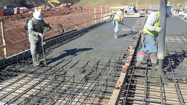
• When concreting is done from high for underground foundations and rafts, which causes concrete to separate.

Way to prevent Segregation of Concrete: When the depth of concrete is more than 1.5 meters it should be located through temporary inclined chutes. The delivery end of chute should be as close as possible to the point of deposit. When Segregation in deep foundations and rafts of thickness is more than 1 meter, there is chance of presence of segregated concrete near bottom or in center without proper supervision. This segregation can be detected by advanced method of testing such as ultrasonic testing.


Segregation of Concrete- Causes and prohibition

~~~~~~~~~~~~~~~~~~~~~~~~
Published By
Rajib Dey
www.constructioncost.co
~~~~~~~~~~~~~~~~~~~~~~~~
Wednesday, May 22, 2019

PyPile- a pile analysis software program

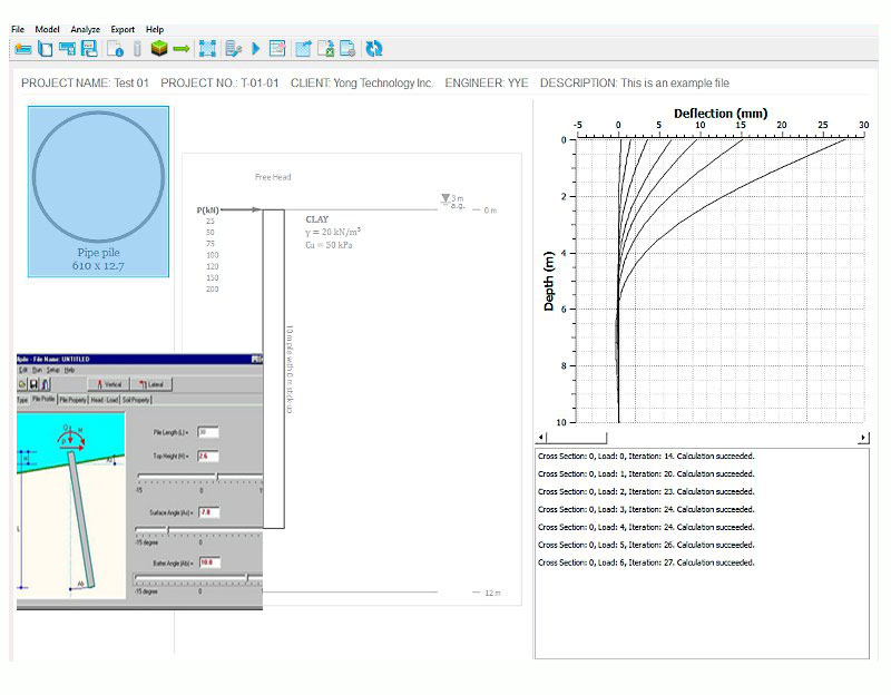
PyPile is a free sidelong pile analysis software program which is based on p-y curves and used for pile bending, bending moment and shear force analyzing with different load cases.

About Software: PyPile is developed by Yong Technology and the latest version is 0.6.3 which is available for both Windows and Mac. This software has the file size of 11.79 MB so it doesn’t take much space and has the license of Freeware so basically it is virus free. This software comes with common pile cross sections and custom cross section; it also included basic soft clay, stiff clay, sand p-y curves (Barry J. Heyer and Lymon C. Reese) and customized p-y curves. Free or fixed pile-head boundary conditions are also available to users.

Features:

This software is built-in typical soft clay stiff clay and sand p-y curves.
• It has custom p-y curves which are defined by JavaScript or pricewise lines.
• Multi-layered soil considered in it.
• P multiplier is used to reduce p value in p-y curves.
• There are both Common pile cross sections and Custom cross sections.
• Pile El Multiplier is used to increase or reduce pile bending stiffness.

• Free and fixed pile head boundary conditions are used.
• Lateral force and pile head moment combinations are also used.
• Different results output like deflection, moment, shear force and rotation angle can come as excel xlsx file. 
• Soil profile graph is ready to be exported and used in report.
Source www.cesdb.com
PyPile- a pile analysis software program

~~~~~~~~~~~~~~~~~~~~~~~~
Published By
Rajib Dey
www.constructioncost.co
~~~~~~~~~~~~~~~~~~~~~~~~
Monday, May 20, 2019

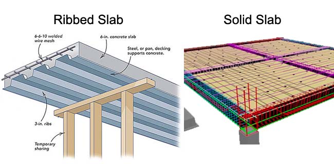
Difference between Ribbed Slab and Solid Slab

Slabs are actually structural members made for floors and roofs in buildings which may be formed of solid thickness or ribbed with ribs running in one or two directions.

About Slab: Slab is a useful element which is made to create flat and useful surfaces like floors, roofs and ceilings of a building. It is a horizontal structural component with top and bottom surfaces parallel or near so. Commonly these slabs are supported by walls, beams, columns or the ground. The depth of a concrete slab floor is very small similar to its span.

These slabs may be solid of uniform thickness or ribbed with ribs running in one direction or two directions or waffles.

Ribbed Slabs: These types of slabs are slabs cast completely with a series of closely spaced joist which in turn are supported by a set of beams. The main benefit of ribbed floors is the lowering in weight achieved by removing part of concrete below the neutral axis. This creates this type of floor economical for buildings with a long span with light or moderate loads.

Solid Slabs: Solid slabs are completely customizable concrete slabs of varying width, length and thickness which can be cast with specially inserts to lift, mounting or connecting hardware. These slabs of uniform thickness can be one-way or two-way:

• One way slab: When a slab is supported on all four sides and the proportion of long span to short span is equal or may be greater than two, it is definitely one way slab. The load on this slab is carried by the short span in a direction but the main reinforced bar and distribution bar in transverse direction. Example: Verandah Slab, Cantilever Slab etc.

• Two Way slab: When a slab is supported on all four sides and the proportion of the long span to the short span is less than 2. It is considered as two way slab. The load on this slab is carried by both the short span and long span though the greater amount of load is carried by the shorter span. Example: Slab used in multistory building.

Sourcewww.dailycivil.com

Difference between Ribbed Slab and Solid Slab

~~~~~~~~~~~~~~~~~~~~~~~~
Published By
Rajib Dey
www.constructioncost.co
~~~~~~~~~~~~~~~~~~~~~~~~
7 kinds of Construction failings in Reinforced Concrete Structures

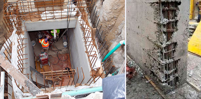
There can be happen several concrete defects in Reinforced Concrete structures which lead the concrete structures weak and make the building defective.

Concrete is a popular building material which often known for its toughness; Concrete is made up with three basic things which are: water, aggregate (rock, sand or gravel) and Portland cement. It is known as a very versatile and reliable material though some construction faults and imprudence can lead to the growth of defects in a concrete structure. These failings can be seen as per poor construction practices, poor quality control or for poor structural design and detailing.

In this article we will discuss about some known defects in concrete structures and the types are written here:

1. Honeycomb and Rock Pockets: This kind of defect can be seen on the concrete structure where gaps are left for the failure of cement mortar to pour spaces around and among coarse aggregates. It happens when poor quality control is mixed during mixing; transporting; or laying of concrete, under or over-compression of concrete, lack of space between bars and low cement content or improper mix design. This kind of defect may reduce durability and make the concrete weak; but if they are minor can be repaired by cement mortar within 24 hours or it can’t be repaired.

2. Poor Formwork Installation: This error includes misalignment, movement, and loss of support, failure of forms which can be lead to cracking and structural failure. The loss of support during construction can increase settlement cracks; while insufficient formwork support and premature removal of formwork are main reasons of loss of support in the construction. These errors can be repaired with surface grinding to maintain the prop of the structure if the error is minor; for major errors, it shall be repaired by removing the concrete in defective area and then building that portion again.

3. Concrete Dimensional Errors: These errors happen when there is poor entering of a structural member or for deviation from the specifications.

4. Finishing Errors: They include over-finishing of the concrete surface or addition of more water or cement to the surface while finishing of the concrete which makes the concrete permeable and makes concrete less durable.

5. Shrinkage Cracks: It happens due to the evaporation of water from the concrete mixture; the intensity of this problem is depended on some reasons like the amount of water in concrete, weather conditions and curing regime.

6. Poor Reinforcement Placement: Defects during reinforcement installation can cause serious concrete deterioration; also insufficient chair bars and lack of tying of reinforcement would cause rebar movement which may cause to insufficient concrete cover and reduction in effect depth of the concrete section. As a result, the durability of the concrete structure is compromised and the structure would be exposed to chemical attacks.

7. Bugholes: Bugholes or surface voids are small regular or irregular cavities made due to the entrapment of air bubbles in the surface during placement and consolidation. They commonly found in vertical cast-in-place concrete like walls and columns. Both the size and number of bugholes vary and depend on form-facing material and condition, release-agent type and application thickness, concrete mix characteristics and placement and consolidation practices.

Source www.theconstructor.org

7 kinds of Construction failings in Reinforced Concrete Structures

~~~~~~~~~~~~~~~~~~~~~~~~
Published By
Rajib Dey
www.constructioncost.co
~~~~~~~~~~~~~~~~~~~~~~~~
Friday, May 17, 2019

Construction Drawing Types In Building

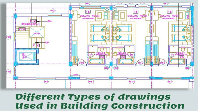
In construction several types of drawings are used to fulfill various purposes. These are known as construction drawings or working drawings.

As for example, working drawing is created for construction project, drawing for approval is intended for submitting to government agencies for sanction and sanctioned drawing is finally delivered to construction site.

After proper examination, justification and rectification in different phases, the drawing is accepted for construction. Construction drawing should contain detail measurement and clear section of each section of building. The following types of drawings are mostly found in construction works :-

• Architectural drawing
• Structural drawing
• Plumbing & sanitary drawing
• Electrical drawing
• Finishing drawing etc.


Architectural drawing: This type of drawing provides the entire view of building. It depicts the position of a building as well as where to arrange each parts of building etc. It retains several other drawing sheets of various names like plan, elevation, section etc.

Structural drawing: It focuses on everything about structure like strength of various segments of structure, structural material, placement, grade and size of reinforcement etc. It also comprises of several other drawing sheets within it with different titles.

Plumbing and sanitary drawing: This type of drawing demonstrates the exact positon of sanitary and water supply piping and fixture and how to attach each fixture etc.

Electrical drawing: This type of drawing provides the position and details of electrical wiring, fixtures and sub-station etc. It also presents the electrical load calculation.

Finishing drawing: It contains all drawing regarding finishes and out looking of building like tiles, marble granite etc. Sometimes this type of drawing is contained with architectural drawing.

Construction Drawing Types In Building

Read more
~~~~~~~~~~~~~~~~~~~~~~~~
Published By
Rajib Dey
www.constructioncost.co
~~~~~~~~~~~~~~~~~~~~~~~~
Thursday, May 16, 2019

Types of reinforcement or mesh in several footings (foundations)

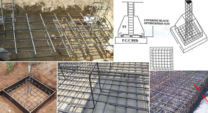
Different types of Reinforcement in footings or types of mesh used in foundation:-

Several types of reinforcement exist in footings. The reinforcement should be provided in footings for tension requirements. Normally, the percentage of reinforcement in footings should remain among 0.5% to 0.8%. Based on the load analysis, the structural engineer design the type of Mesh in footings. Given below, the details about he types of mesh (reinforcement) implemented at several types of footings or foundations.

Usually, four different types of reinforcement in footings or foundations are found :–

1. Plain Mesh: This type of Mesh is normally implemented at plain or isolated or combined footings. It is specifically useful for low-rise buildings. Prior to use plain mesh to high rise buildings, the load should be analyzed in accordance with this mesh and determine either the type of mesh is balanced with the load or not.

Under this type, bars are arranged as a grid. It may contain bars with various diameter and spacing in either direction. The spacing may or may not vary in both directions.

2. Mesh with hooks (Hook Mesh): It is suitable for both low rise and high rise buildings. The footing is reinforced as grid and the bars are arranged with hook at the ends of the mesh. The perfect anchorage of the reinforcement can be obtained by bending the bars ends. Normally, the standard length of hook is 10D where D stands for the diameter of the bar.

3. Footing Mesh up to the depth of Footing: It has similarity with Plain footing. Under this type of footing, the bars are bent at ends up to a height of footing. The concrete cover of 1″ to 4″ should be arranged in all the sides of footing.

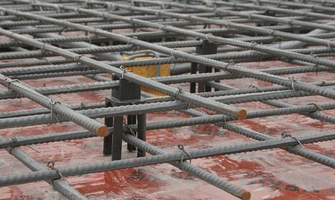
4. Raft Mesh: This type of Mesh is ideal for raft footing. Raft footing is suitable when the bearing strength of soil is very low. Under this type, mesh is segregated into two parts like top mesh and bottom Mesh.

Initially, the bottom mesh is arranged on covering blocks, ends of a bottom mesh are bent at an angle of 90 degree up to a height of 50D where D stands for Dia of Bar. After that top mesh is attached with the bottom mesh in opposite direction. Besides, the top mesh equivalent to bottom mesh is bent with 90 degrees but an additional bar of 50D is not arranged since it is already equipped on bottom mesh.

The 50D extra bar is arranged either on bottom or top mesh.

Single ring or double rings are attached with top mesh and bottom mesh to retain the proper framework. The rings allow the steel reinforcement not to distort in any direction. Least diameter of bars used for rings should be 6 mm.

In single ring raft mesh, rings are arranged in only one direction either horizontal or vertical, while in double ring system, the rings are arranged in both the direction.

The following points should be taken into consideration :-

1. Concrete cover differs from 1" to 4" depending on the size of the footing.
2. Hook length in Hook mesh is always 9D, where D stands for Dia of bar.
3. Additional bar is arranged either on top or bottom mesh and additional bar length is 50D.


Types of reinforcement or mesh in several footings (foundations)

Read more
~~~~~~~~~~~~~~~~~~~~~~~~
Published By
Rajib Dey
www.constructioncost.co
~~~~~~~~~~~~~~~~~~~~~~~~
Wednesday, May 15, 2019

Steps involved in cement concrete works

Given below, brief specifications for executing cement concrete works for different objectives :-

1. Materials for Cement Concrete: Different types of materials cement, aggregates and water are required for cement concrete works. The aggregates are categorized as fine aggregates (sand) and coarse aggregates. The aggregates should comprise of inert material and should be clean, dense, hard, robust, long-lasting, non-absorbent. Besides, it should have the ability to make superior bond with the cement mortar.

Cement - Fresh Portland cement or pozzolana Portland cement (PPC) should be used according to requirement or specification and should contain the necessary tensile and compressive strength and fineness.

Fine Aggregates - Course sand with hard, sharp and angular grains should be utilized as fine aggregate or sand and it should get through 5mm (3/16”) square sieves or mesh. It should contain standard quality and does not contain dust, dirt and organic matters. Sea sand is not recommended for concrete works. Fine aggregates should comprise of crushed stone or manufactured sand if indicated.

Coarse Aggregates - These should comprise of hard broken stone of granite or similar stone and does not contain dust, durst and other foreign materials. The size of stone ballast should remain 20mm (0.75 inches) and less and should be arranged on 5mm (0.25 inch) square mesh. These should be well grades to retain voids under 42%.

The size of coarse aggregate is based on the thickness of concrete and nature of work. As for instance, size of coarse aggregates for building works should remain 20mm and 40mm to 60mm sizes are applied for road work and mass concrete works.

Water - The quality of water should be same as drinking water and it does not contain alkaline and acid matters.

2. Proportioning of Cement Concrete: The proportions in cement concrete should be according to the design and strength requirements. The proportion can be 1:2:4 (M15 concrete) or 1:1.5:3 for M20 concrete. The proportions of 1:2:4 concrete include the ratio of cement: sand: coarse aggregates by volume until indicated. Least compressive strength of concrete of 1:2:4 mix proportion should be 140 kg/sq.cm or 2000 lbs/sq.in on 7 days.

3. Measurement of Materials: Sand and coarse aggregates are calculated by volume with boxes. Cement should not be calculated by box, one bad of cement of 50kg weight should be treated as 1/30 cu.m or 1.2 cu.ft volume. Size of measured boxes may be 30 cm x 30 cm x 38 cm or 35 cm x 35 cm x 28 cm similar to the content of one bag of cement.

All materials should be dry and in case of utilizing damp sand, compensation should be done with extra quantity sand to the extent necessary for bulking of sand.

4. Mixing of Cement Concrete: Mixing of concrete should be done with machine to attain superior quality. For small works, hand mixing by batches is suitable.

5. Checking for Concrete Slump: Slump test should be conducted constantly to control the addition of water and to retain the desired consistency. A slump of 7.5cm to 10 cm (3 inches to 4 inches) is perfect for building work and 4 cm to 3 cm (1.5 inch to 2 inches) is ideal for road work.

6. Formwork for Concrete Works: Formwork centering and shuttering should be arranged as per need and the standard specifications prior to place concrete to confine or to support or to retain the concrete in exact location. The inside surface of the concrete should be oiled with formwork oils so that the concrete can’t stick to it.

Before placing concrete, water should be sprinkled over the base and formwork where the concrete will be arranged. Forms should not be detached prior to 14 days in general, side forms may however be detached after 3 days of concreting.

7. Placing of Concrete: It is necessary to place concrete gently in layers not surpassing 15cm or 6 inches and it should be consolidated by pinning with rods and tamping with wooden tampers or with mechanical concrete vibrating machines unless a solid concrete is produced.

Concrete should be placed constantly. If the placing of concrete is postponed for rest of the day or for the following day, the end should be sloped at an angle of 30 degrees and made rough for jointing again.

Curing of Concrete: After about two hours of placing when the concrete starts to become solid gradually, it should be retained moist by covering with wet gunny bags or wet sand for 24 hours and then curing by flooding with water making mud walls of 7.5 cm or 3 inches high or by covering with wet sand or earth and kept damp constantly for 15 days.

Steps involved in cement concrete works

Read more
~~~~~~~~~~~~~~~~~~~~~~~~
Published By
Rajib Dey
www.constructioncost.co
~~~~~~~~~~~~~~~~~~~~~~~~
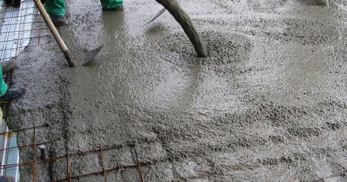
Tuesday, May 14, 2019

Details about concrete cover in reinforcement

Concrete cover means the minimum distance among the surface of implanted reinforcement and the exterior surface of the concrete according to ACI 130 code. The concrete cover depth is calculated with a cover meter.

The purpose of the concrete cover is to safeguard the reinforcement.

While making design of reinforced concrete structures, the reinforcement already arranged is implanted in the concrete up to a specific distance from the face of the member due to the following grounds:

• To safeguard the reinforcement against corrosion.
• To make reinforcement as a good fire resistant.
• To arrange adequate entrenched depth in order to provide necessary stress to reinforcement.


This distance is calculated in several methods and recognized with various names:

1. Clear cover: It stands for the distance from the face of the member to the most exterior face of the reinforcement along with shear or torsion Stirrups or links.

2. Nominal cover: It has similarity as clear cover though with a dissimilar name. This term is applied with the code. It belongs to the distance calculated from the face of the member to the most exterior face of the reinforcement along with Stirrups or links. It is the dimension demonstrated in drawings and detailing.

3. Effective cover: It is the distance calculated from the face of the member to the center of area of the main reinforcement i.e. the tension or compression reinforcement. It refers to the dimension generally applied for design calculations.

Effective cover = Clear cover + (Dia of Stirrups/links) + 0.5 * (Dia of main reinforcement bars).

Also,
Effective cover = Overall depth – effective depth.


At each end of reinforcing bar, concrete cover should not be under 25 mm or less than twice the diameter of the bar.

For a longitudinal reinforcing bar in a column, concrete cover should not be under 40 mm or under the diameter of such bar. In case of columns with least dimension of 20 cm or under, whose reinforcing bars do no not goes beyond 12 mm, concrete cover of 25 mm should be applied for reinforcement.

For longitudinal reinforcing bars in a beam, the concrete cover should not be under 30 mm or less than the diameter of the bar.

For tensile, compressive shear or other reinforcements in a slab or wall, the cover should not remain under 15 mm or under the diameter of such bar.

For footings and other major structural members in which the concrete is arranged directly against the ground, cover to the bottom reinforcement should remain 75 mm. If concrete is poured on a layer of lean concrete, the bottom cover should be minimized to 50 mm.

Details about concrete cover in reinforcement

Read more
~~~~~~~~~~~~~~~~~~~~~~~~
Published By
Rajib Dey
www.constructioncost.co
~~~~~~~~~~~~~~~~~~~~~~~~