adsense analytic

Showing posts with label columns. Show all posts

Monday, March 30, 2020

How beam and lintel differs as per structural behavior & load carrying system

This construction video tutorial briefly explains the variations among beam and lintel.
Both the beam and lintel are flexural as well as horizontal members and considered as the vital parts of structural system. But these differ according to their structural behavior and load carrying system.
Given below the points of differentiation:-
How beam and lintel differs as per structural behavior & load carrying system
~~~~~~~~~~~~~~~~~~~~~~~~~~
Published By
Rajib Dey
www.constructioncost.co
~~~~~~~~~~~~~~~~~~~~~~~~~~

Thursday, March 26, 2020

How to resolve incorrect myth about column construction

The super structure can be developed in different methods. The walls of houses for two to three storied structures can be constructed with bricks containing the slabs, lintels, chajja etc. in reinforced concrete in the regions where superior quality bricks are obtainable.
Such construction is known as load bearing construction due to the whole load generating from the slabs, beams, walls etc is delivered to the foundation via the brick walls.
In the regions where natural disasters like earthquake or high speed storms occur frequently, such load bearing wall construction is unsafe for resisting horizontal drifts if not retrofitted. This type of construction is appropriate upto G+2 storied building on the whole.
The demand for RCC (Reinforced Cement Concrete) framed construction will be increased to cope up with the requirement of developing high storied building with natural hazards.
Generally, RCC framed construction comprises of a series of columns which are arranged properly in the house and interconnected with beams to build a frame. These columns deliver the building load to soil located below via RCC footings.
The frame, starting from the foundation, has to be designed by A structural engineer will design the frame that start from the foundation as well as settle on the mix of concrete to be applied, the sizes of columns and beams, the reinforcement to be arranged therein, on the basis of the loads to be retained by the structure.
Definition of Column: Column stands for a vertical compression member that transfers the load of the structure to foundations. They are reinforced with the use of main longitudinal (vertical) bars to withstand compression and/or bending; and transverse steel (closed ties) to withstand shearing force.
How to resolve incorrect myth about column construction
~~~~~~~~~~~~~~~~~~~~~~~~~~
Published By
Rajib Dey
www.constructioncost.co
~~~~~~~~~~~~~~~~~~~~~~~~~~

Thursday, March 12, 2020

The four types of Shallow Foundation

Shallow foundation is applied in cases where we can find good load-bearing soil at a rather low depth. The foundation depth must meet the safety requirements of the breakdown. That is, after the application of load, the complete structure settlement will be within acceptable limits.
We can use the following four types of shallow foundations: Spread Footing, Combined Footing, Raft Foundation and Ring Foundation.
1. Spread Foundation: You need to spread the load from the column or wall to a larger area, you should use Spread Foundation. The width of the footing area is much wider than the wall or column.
The spread footing that is used to support a wall is called a wall footing or continuous footing. The top of the footing may be stepped or tapered, increasing the width gradually from wall or column to the base. They are of the following types:
a) Strip Footing: This primitive type of footing has been conventionally used in most constructions historically, before more modern inventions. They are mostly made of stones, masonry or concrete. The strip footing that is constructed of stone blocks generally has a stepped top. In modern days, however, the use of strip footing has become next to obsolete. Only in some light loading residential construction is strip footing still used.
b) Isolated Footing: When you provide footings under columns separately in a framed structure, it is called Isolated footing, pad footing or column footing.
In most cases, square footings are used under columns. However, space restrictions may force you to use rectangular footings. In case of circular columns, circular footings may be used, though it is not common. It may be used in special circumstances where construction work is difficult, or the load has to be dispersed very equally.
2. Combined Footing: When two columns are too close to make separate footings for each, then their footings are combined. These may be of the following three types:
a) Rectangular footing: These are the most common types of combined footing. It’s basically two square footings constructed together. This is used when each column is bearing the same load and of the same size.
The four types of Shallow Foundation
~~~~~~~~~~~~~~~~~~~~~~~~~~
Published By
Rajib Dey
www.constructioncost.co
~~~~~~~~~~~~~~~~~~~~~~~~~~

Friday, March 6, 2020

Construct Earthquake Resistant Buildings by Simple Means

The engineering science is continuing to advance in response to seismic threats. There have been significant breakthroughs in the field. However, most of them are very complex and require exceptional machinery. Not to mention, expensive as well. However, there are some simple ways to build a structure that will be resistant to earthquake damages up to a certain level.
In areas where seismic activity is not too harsh, we can utilize these techniques to same money and complexity but make the building resistant to seismic activities.
Structure Stiffness: The most traditional way to fight quakes is to use stronger materials to construct the building. Stiffer or heavier members can be used to fight the lateral forces generated during seismic activities. For special quake-proof structures, ACI codes prescribe at least 10” thick members.
Geometrical Absorption: The building can be planned in such a regular and special geometrical shape that it disperses the seismic forces evenly so that no particular member experiences excessive force. This naturally fares much better than a poorly-planned unsymmetrical building.
For existing buildings that are structurally asymmetrical, you can use seismic joints and expansion points in places where the forces are dispersed unevenly. Providing extra columns, shear walls, and framing can make the weaker section withstand the extra forces to a good level. Parking levels should have extra reinforced columns in order to negate the soft story effect.
Lateral Force Resistance: Using three types of lateral force resisting systems, we can try to negate much of the seismic forces. These are:
1. Moment Resisting Frame System: it is designed to resist all types of earthquake generated forces acting on the structure. They can be customized to fit the seismic activity scale of the region.
2. Building Frame System: these are designed to resist gravitational loads only, but they function excellently in that. A shear wall is added to resist the lateral forces acting on structure.
3. Dual Frame System: this is a combination of the above two systems. Shear walls along with moment resisting frames work excellently to fight off the vibrations and displacements from an earthquake. But, of course, they are more complex and costlier to build.
Construct Earthquake Resistant Buildings by Simple Means
~~~~~~~~~~~~~~~~~~~~~~~~~~
Published By
Rajib Dey
www.constructioncost.co
~~~~~~~~~~~~~~~~~~~~~~~~~~

Wednesday, February 26, 2020

Types of Foundations in Construction Industry

Today, we shall talk about the common sorts of foundations in buildings. Generally, all foundations are divided into 2 categories: shallow and deep. The words ‘shallow’ and ‘deep’ check with the depth of soil during which the inspiration is created.
Shallow foundations may be created in depths of as very little as 3 feet, whereas deep foundations may be created at depths of sixty – 200 feet. Shallow foundations are used for little, lightweight buildings, while deep ones are for giant, serious buildings. The following sorts of Foundations In Building Construction may be elaborated below.
Raft or Mat Foundations: Raft Foundations, conjointly referred to as Mat Foundations, are most frequently used once basements are to be made. In a raft, the complete basement floor block serves as the foundation; the burden of the building is unfold equally over the entire footprint of the building. it's referred to as a raft as a result of the building is sort of a vessel that ‘floats’ in an exceedingly ocean of soil.
Mat Foundations are used wherever the soil is weak, and thus building hundreds have to be compelled to meet an oversized space, or wherever columns are closely spaced, which suggests that if individual footings were used, they might hit one another.
Shallow Foundations: Shallow foundations are referred to as unfold footings or open footings. The ‘open’ refers to the very fact that the foundations are created by 1st excavating all the planet until all-time low of the footing, so constructing the footing. Throughout the first stages of labor, the complete footing is visible to the attention, associated is so referred to as an open foundation.
The concept is that every footing takes the focused load of the column and spreads it out over an oversized space,so that the particular weight on the soil doesn't exceed the safe bearing capability of the soil.
There are many forms of shallow footings: individual footings, strip footings and raft foundations.
In cold climates, shallow foundations should be protected against freezing. This can be as a result of water within the soil round the foundation can freeze and expand, thereby damaging the inspiration. These foundations ought to be engineered below the frost line, that is that the level within the ground higher than which freeze happens.
If they can't be engineered below the frost line, they must be protected by insulation: commonly a touch heat from the building can permeate into the soil and forestall freeze.
Types of Foundations in Construction Industry
~~~~~~~~~~~~~~~~~~~~~~~~~~
Published By
Rajib Dey
www.constructioncost.co
~~~~~~~~~~~~~~~~~~~~~~~~~~

Saturday, January 11, 2020

Thumb Rules to Follow While Designing Columns

Columns are essential support structures that are almost inevitably used in any construction projects. From ancient times, columns have been an indispensable part of erecting buildings, them being one of the most important load-bearing members. Obviously, one needs to be careful while designing such important structures.
As per the construction sciences and technologies, there are many rules applicable to specific columnar structures. However, there are some few basic rules of column designing that all engineers can keep in mind while designing most types of columns and similar vertical supports.
Today, we will discuss these important thumb rules of column design in this article. Needless to say, columns need to be designed keeping in mind the total amount of forces acting on the structure. But also, keeping these basic guidelines in mind can prevent architects and engineers from making silly mistakes.
Rule 1: Essentially, the size of the columns would depend upon the total amount of forces acting on the column. In short you can consider this as the total load on a column. This will make or break the column, so you need to be ensuring that your columns design can withhold this entire load and anything else that may come later.
That is, the total load on a column may be not only the weight of the structure that it bears, but also the movable materials that structure will bear. For example, while designing a multi-storied godown, you will need to care about not only the weight of the floor and the walls and the roof, but more also, the weight of the goods that are going to be stored on that floor. This can get pretty great in case of solid materials.
Thumb Rules to Follow While Designing Columns
~~~~~~~~~~~~~~~~~~~~~~~~~~
Published By
Rajib Dey
www.constructioncost.co
~~~~~~~~~~~~~~~~~~~~~~~~~~

Tuesday, August 27, 2019

Basic differences among foundation & footing

Foundation: It is the portion of a building that is built up underneath the ground level and keeps direct contact with sub-strata. It transfers the complete load of the building to the subsoil in which it stands in such a manner that settlement of the soil is not collapsed in shear.
Footing: It is the bottom most part of a vertical structure (column, wall) that finally transmits the weight from walls and columns to the soil or bedrock.
Footing is mainly the segment of foundation of any modern structure.
Variation among footing and foundation
Given below, the basic variations among Footing and Foundation:
1
The footing is a formation that is in touch with the ground.
Foundation belongs to a structure that transfers its gravity loads to earth from superstructure.
2
Footing is analogized with the feet of the leg.
Foundation is compared with legs.
3
The footing refers to a type of shallow foundation.
Foundation is both shallow and deep.
4
Footing comprises of slab, rebar which are made of brickwork, masonry or concrete.
Foundation types comprise piles, caissons, footings, piers, the lateral supports, and anchors.
5
Footing reinforces support to a separate column.
Foundation stands for an extensive support since it provides support to a group of footings as a whole building.
6
A number of footings rest on a foundation.
Foundation is the support that sustains different types of loadings.
7
A footing remains under the foundation wall.
Foundations stand for the basement walls.
8
Footing directly transfers loads to the soil.
Foundation is directly related with the soil and passes it on the ground.
9
All footings are foundations.
Not all foundations are footings.
Basic differences among foundation & footing

~~~~~~~~~~~~~~~~~~~~~~~~~~
Published By
Rajib Dey
www.constructioncost.co
~~~~~~~~~~~~~~~~~~~~~~~~~~

Tuesday, August 13, 2019

Variations among framed structures & load bearing structures

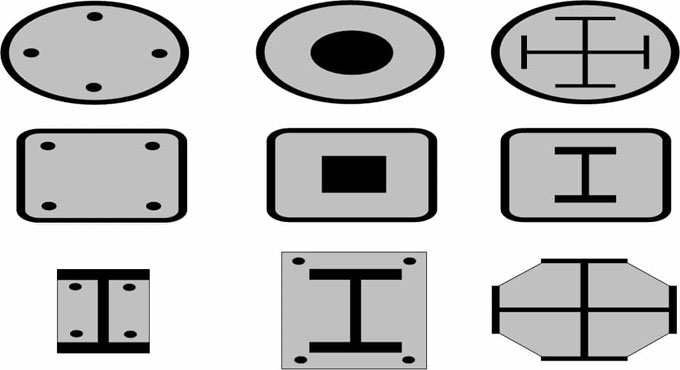
Structures are available with several models like solid, framed, shell, load bearing, membrane, composite, trusses, cables and arches, surface structure etc. They are categorized depending on the geometry so as to obtain strength and withstand various types of loads.
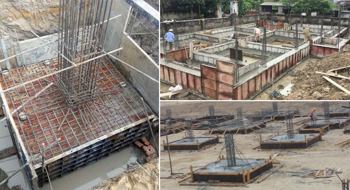
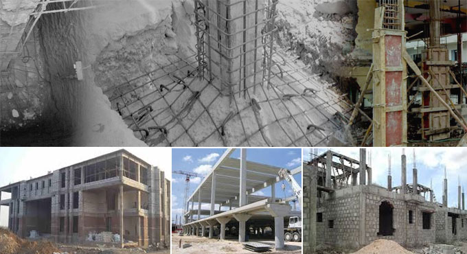
Under a framed structure system, a framework or ‘skeleton’ comprising beams and columns is applied to bear the structural loads down the building to the foundations. Generally, the framework is made of steel or reinforced concrete, but in very small (normally single-storey) structures, it is built with timber or aluminium.
Under a non-framed structure system, the wall itself becomes load-bearing. These load-bearing walls are normally constructed by masonry, but reinforced concrete is also used to build up them. Here, the loads are transferred to the foundations through walls.
Given below, the points of variations among framed structure and load bearing structure.
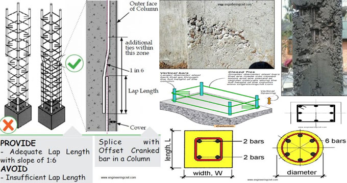
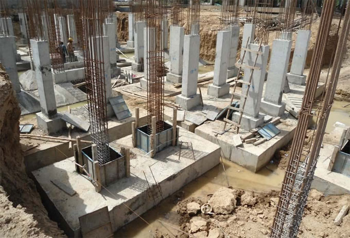
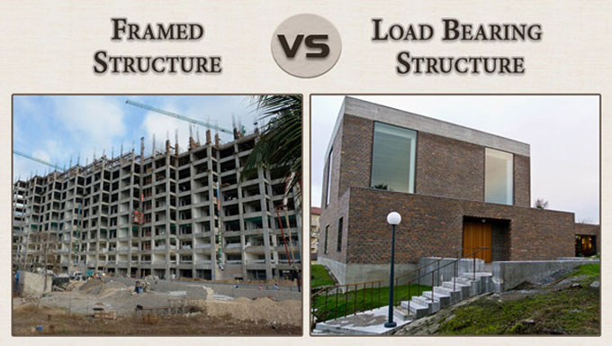
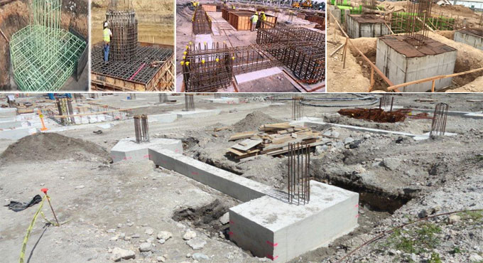
1. Framed Structure: A framed structure integrates different structural components like beam, column and slab which are attached together to defend the gravity and various lateral loads. The purpose of these structures is to control the large forces, moments caused by the applied loads.
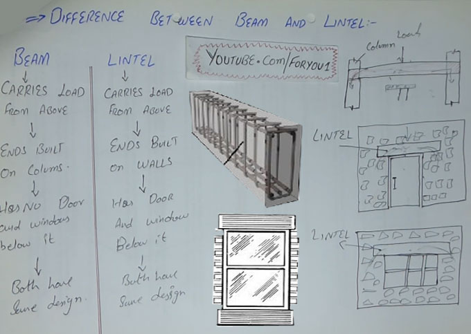
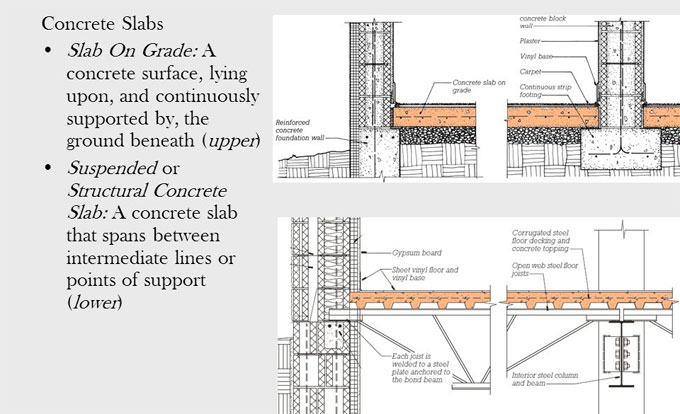
Load Bearing Structure: In Load bearing structure, the loads of the roofs along with lateral loads are carried by walls, and through walls they are delivered to lower floor and finally to foundations.
2. Framed Structure: Framed structure contains beam, column, and slab.
Load Bearing Structure: Load bearing structure contains heavy masonry walls with brick or stone that provides support to the whole structure.
3. Framed Structure: In framed structure, vertical load transfer path directs from slab/floor to beam, beam to column and column to footing and then to soil.
Load Bearing Structure: In load bearing structure, vertical load transfer path directs from slab/floor to walls and walls to footing.
4. Framed Structure: Multi storey buildings with various heights are built up. These buildings are normally suitable for office, hotel, residential apartment and provide the vertical circulation in the form of stairs and lifts which engross up to 20% of the floor area.
Load Bearing Structure: Limited storey buildings are built up. For load-bearing construction, in several countries, even 14 storied buildings are constructed only with masonry.
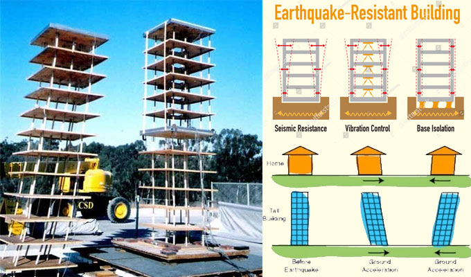
5. Framed Structure: Framed structure has strong resistance capacity against Earthquake.
Load Bearing Structure: Load bearing structure is not very effective to withstand Earthquake due to its limitations. But for low rise buildings, it functions equally well.
6. Framed Structure: In framed structure all the walls are leaner.
Load Bearing Structure: In load bearing structure walls are denser.
7. Framed Structure: In these types of structures, there are lots of carpet areas and they are leaner.
Load Bearing Structure: In these types of structures less carpet area is available, as walls are thicker and hence carpet area efficiency of planning is less.
8. Framed Structure: Less excavation is required for this type of construction.
Load Bearing Structure: Higher excavation is required for this type of construction.
9. Framed Structure: It is less material intensive.
Load Bearing Structure: It is more material intensive and as a result the dead load is increased
10. Framed Structure: Thickness of wall is unchanged during the construction. Thickness of wall is not changed if the height is raised.
Load Bearing Structure: Thickness of wall remains inconsistent during the construction. The thickness of the wall is raised when the height is higher.
Variations among framed structures & load bearing structures

~~~~~~~~~~~~~~~~~~~~~~~~
Published By
Rajib Dey
www.constructioncost.co
~~~~~~~~~~~~~~~~~~~~~~~~

Saturday, July 27, 2019

Details about Composite Slabs & Columns and their benefits

Composite slabs:
1. It comprises of profiled steel decking with an in-situ reinforced concrete topping.
2. The decking(profiled steel sheeting) perform as permanent formwork to the concrete as well as offers adequate shear bond with the concrete in order that when the concrete has attained strength, the two materials function mutually & compositely.
3. Distance among 3 m and 4.5 m onto supporting beams or walls.
4. When the slab is unpropped throughout construction, the decking single-handedly withstands the self-weight of the wet concrete and construction loads. Subsequent loads are delivered to the composite section.
5. When the slab is propped, all of the loads should be combated by the composite section.
6. These are normally designed as simply supported members in the normal condition.
Profiled steel sheeting:
1. Depths vary from 45 mm to over 200 mm.
2. Yield strengths vary from 235 N/mm2 to minimum 460 N/mm2.
3. The thickness vary from 0.8 mm to 1.5 mm.
4. The different shapes offer Interlock among the steel and concrete.
5. Decking is also applied to make the beams stable against lateral torsional buckling throughout construction.
6. Improve the stability of the building entirely by behaving as a diaphragm to transmits the wind loads to the walls and columns.
7. Temporary construction load normally manages the choice of decking profile.
Composite Columns:
A steel-concrete composite column stands for a compression member that contains either a concrete encased hot-rolled steel section or a concrete filled tubular section of hot-rolled steel. The existence of the concrete is granted for two ways.
1. Safeguard from fire.
2. It may also withstand a small axial load.
3. To minimize the effective slenderness of the steel member, that raises its resistance capacity against axial load.
The bending stiffness of steel columns of H-or I-section is superior in the plane of the web (‘major-axis bending’) as compared to a plane parallel to the flanges (‘minor-axis bending’).
The ductility performance of circular type of columns is considerably superior as compared to rectangular types. There is no need to offer extra reinforcing steel for composite concrete filled tubular sections.
Protection from erosion is arranged by concrete to steel sections in encased columns.
When the local buckling of the steel sections is removed, the reduction in the compression resistance of the composite column caused by overall buckling should definitely be permitted. The plastic compression resistance of a composite cross-section shows the maximum load that can be employed to a short composite column.
Details about Composite Slabs & Columns and their benefits

~~~~~~~~~~~~~~~~~~~~~~~~
Published By
Rajib Dey
www.constructioncost.co
~~~~~~~~~~~~~~~~~~~~~~~~

Wednesday, July 24, 2019

Construction Method Of Concrete Slab On Grade

Slab on grade belongs to concrete floor slabs which are poured at grade or ground level to develop a foundation for a home. Prior to start the construction, contractors excavate the soil adjacent to the area where the foundation should be constructed and ensure that the ground has sufficient strength to support the structure.
Normally, the periphery of the slab is very dense as compared to the rest of the surface. This section has similarity with footer that facilitates to circulate the weight of the exterior walls uniformly over the soil underneath the structure. Slab on grade foundations are suitable for the areas where the soil is unusable for crawl spaces or basements.
Grade slabs are provided in areas where the ground is not solidified. This type of slabs may or may not include reinforcement in it. The inclusion of reinforcement depends on the floor loads and local building codes.
The thickness of Grade Slab should be at least 4 inches. If porosity exists in soil, the thickness of the slab should be raised. To maintain safety, a layer of gravel & bitumen should be placed on earth prior to arrange concrete slab to stop the penetration of moisture content into the slab.
Slab on Grade is categorized as follow:
1. Supported Slab on Grade
2. Monolithic Slab on Grade
Supported Slab on Grade / Grade Slab: Supported grade slab or slab on grade foundation should be used when the conventional footings are already set up on site to uplift the columns. Under this system, the wall is laid on a footing and the grade slab stands on a layer of gravel and moisture barrier.
The formwork applied for plinth beams operates as batter boards for slab mould. There is an expansion joint among concrete slab and wall to reduce the stress throughout high-temperature days. Control joints are set in a planned grid with chalk lines to manage occasional cracking on the slab.
Monolithic Slab on grade: There are no footings for monolithic grade slab, the concrete slab itself functions as a footing for the building; and the columns, walls are uplifted from the grade slab. This type of slab is structured with batter boards around the slab based on the plan and the concrete is poured inside batter boards. These batter boards operate as a mould to detect the slab corners.
Grade slabs normally stand on the layers of gravel and moisture barrier. These layers can resist penetration of water into the slab to develop surface cracks.
The periphery of the grade slab is very dense as compared to the rest of surface. This dense section operates as a mini footing and facilitates to circulate top loads more consistently over the adjacent soil.
Construction Method: Prior to cast slab on grade, the excavation of earth is done to the desired depth along with compaction to drive out air voids. Batters are leveled and provided in exact location based on the plan prior to concrete pour. These boards function as a concrete mould to facilitate detecting the slab corners.
After that, soil investigation is performed to design the thickness of the slab. After obtaining the results, the layers of gravel and moisture barriers (bitumen) is again poured on the ground. These layers are used as a sub-base for slab and resist the infiltration of moisture into the slab.
The thick concrete is poured at the edges to form an solid footing and reinforcement rods are placed to increase the strength of the edges.
To reduce random cracking on the surface, the concrete should be cured and dried for long times.
The expansion joint should be arranged among the wall and slab. The control joints on the slab are leveled with chalk lines prior to pouring which can check random cracking.
Construction Method Of Concrete Slab On Grade


~~~~~~~~~~~~~~~~~~~~~~~~
Published By
Rajib Dey
www.constructioncost.co
~~~~~~~~~~~~~~~~~~~~~~~~

Tuesday, July 16, 2019

Guidelines for making perfect structural design

This civil engineering article focuses on the least standards which should be maintained for the design of various RCC structural elements like the columns, beams, slab and foundation as well as the least safe standards for the reinforcing bars to be applied for making the design of the above mentioned structural elements.
Minimum cross-sectional dimension for a Column should be 9″x 12″ (225 MM x 300 MM). It is the minimum approved size.
It is always recommended to utilize M20 grade concrete for construction as per IS 456:2000. The least steel in a 9″ x 9″ column should be 4 bars of 12 MM with stirrups of 8 MM steel rings at a spacing of 150 MM centre to centre. In a 9″ x 12″ column, more bars (6 bars with 12 mm diameter) should be added to sustain the total efficiently.
Least RCC beam size should not be lower than 9″x 9″ (225MM X 225MM), with an supplementary slab thickness of 125 MM.
Normally, there should be minimum of 4 bars, with 2 bars having 12 MM thickness in the bottom of the beam, and 2 bars having 10 MM at the top of the beam.
A concrete cover of 40 MM should also be provided. It is suggested to utilize M20 grade of concrete (1 part cement : 1.5 parts sand : 3 parts aggregate : 0.5 parts water).
Minimum thickness of RCC slab should be 5″ (125MM) since a slab may comprise of electrical pipes which are implanted into them which could be 0.5″ or more for internal wiring and as a result the depth of slab is decreased at specific places that lead to cracking, weakening and water leakage throughout rains. Therefore, a least thickness of 5″ should be retained.
Minimum size of foundation for a single storey of G+1 building should be 1m x 1m, where safe bearing strength of soil is 30 tonnes per square meter, and the anticipated load on the column does not surpass 30 tonnes.
The depth of footing should be minimum 4′under ground level. It is suggested to get to depths up to had strata.
Minimum Reinforcing bar details:
1. Columns: 4 bars of 12mm steel rods FE 500.
2. Beams: 2 bars of 12 mm in the bottom and 2 bars of 10 mm on the top.
3. Slab
a) One Way Slab: Main Steel 8 MM bars @ 6″ C/C and Distribution Steel of 6 mm bars @ 6″ C/C
b) Two Way Slab: Main Steel 8 MM bars @ 5″ C/C and Distribution Steel of 8 mm bars @ 7″ C/C
4. Foundation: Initially, there should be 6″ of PCC layer. Over it, a tapered or rectangular footing with minimum 12″ thickness should be arranged. Steel mesh of 8 mm bars @ 6″ C/C should be placed. In a 1m X 1m footing, there should be 6 bars of 8 mm on both segments of the steel mesh.
Guidelines for making perfect structural design

~~~~~~~~~~~~~~~~~~~~~~~~
Published By
Rajib Dey
www.constructioncost.co
~~~~~~~~~~~~~~~~~~~~~~~~

Monday, July 15, 2019

Common thumb rules for civil engineering works

Thumb Rules is very important for any civil engineer, Site engineer or civil supervisor to obtain instant decisions on the construction site. By applying thumb, the engineers can get the solution with a simple mathematical formula and take proper decisions wherever required. Before applying these thumb rules, it should be kept in mind that the thumb rule can only provide fairly accurate results never the correct results.

The following types of thumb rules for civil engineers are commonly used in construction work :-

Thumb rule for measuring the Concrete Volume relating to the area:
The volume of concrete necessary = 0.038 m3/square feet area.


As for instance, if Plan Area = 40 x 20 = 800 Sq. m., total necessary volume of concrete will be as follow :-
= 800 x 0.038m3 = 30.4m3


Thumb rule for Steel quantity necessary for Slab, Beams, Footings & Columns:
Essential quantity of steel in residential buildings = 4.5 Kgs – 4.75 Kgs / Sq. Ft.
Essential quantity of steel in commercial buildings = 5.0 Kgs-5.50 Kgs/Sq. Ft.


Thumb Rules For Civil Engineers recommended by B N Datta for the Steel quantity that will be applied for several members of the building :-

Proportions of Steel in Structural Members:

1) Slab – 1% of the total volume of concrete
2) Beam – 2% of the total volume of concrete
3) Column – 2.5% of total volume of concrete
4) Footings – 0.8% of the total volume of concrete


As for instance, suppose the length, width and depth of the slab are 5m, 4m and 0.15m. Now, the quantity of steel for the slab will be computed as follow :-

Initially, it is required to work out the concrete volume.
The total volume of concrete for the slab = 5x4x0.15 = 3m3


Secondly, work out the quantity of steel with formula as follow :-
Based on the guidelines provided in B. N. Dutta reference book, the quantity of steel in slab is 1% of the total volume of concrete used.
Thumb rule to work out the quantity of steel in above slab = Volume of concrete x density of steel x % of steel member.


The weight of steel necessary for above slab = 3x7850x0.01 = 235 kgs

To make perfect calculation, use bar bending schedule.

To learn how thumb rules are applied to calculate the shuttering area and the quantity of cement, sand, course aggregate in several grades of concrete, click on the following link civiconcepts.com

Read more

Common thumb rules for civil engineering works

~~~~~~~~~~~~~~~~~~~~~~~~
Published By
Rajib Dey
www.constructioncost.co
~~~~~~~~~~~~~~~~~~~~~~~~

Friday, July 12, 2019

Sample quotation for constructing an indoor badminton court

In this civil engineering article, you will get a sample quotation with quantities of construction material to design and develop an indoor badminton court.
SPECIFICATIONS: MAIN FEATURES –
• The structure should contain a basement height of 1’0” from Natural ground level.
• Footing pit size 4’x4’x6’-10mm dia @8” c/c main, 8mm dia @8” c/c alternate.
• Column size – 9”x9” (6 nos 16mm dia and stirrups 8mm dia @8” c/c)
• Plinth size – 9”x9” (4nos 12mm dia main reinforcement and stirrups 8mm dia @ 8” c/c)
• Brickwork should be done with superior quality chamber bricks containing cement mortar in 1:6.
• Basement height 2’-0” Basement inside filling with soil. Over the soil PCC is laid with 1:4:8 with 40mm blue metal.
• Plastering with cement mortar 1:4 exterior wall.
• One coat of white cement and two coats of Asian exterior emulsion should be applied.
• Grano flooring with blue metal chips over PCC in the basement.
THE FOLLOWING MATERIALS ARE UTILIZED:–
• CEMENT: Dalmia/Ultratech/Ramco
• BRICKS: Chamber
• STEEL: ISI
• SHEET: JSW CCGL0.47
• PAINT: ASIAN Paint
Total Area of the Building is supposed to be 54’-0” x 54’-0” = 2916.sq.ft.
Subject: Metal Roofing Shed
‘A’ Truss Length x Width: 58’ Feet x 54’ Feet =3132.Sq. Ft
CLADDING WORK (27’x54’) + (27’x54’) + (30’x54’) + (30’x54’) =6156. Sq. ft
Sub: Fabrication and construction of traditional steel structure with Cooler coated Galvalume.
Columns: Delivery and installation of 12 Numers.150×100 Columns (MS I BEAM Height 32’ Feet) Columns Base Plates should have 20 mm thickness 300 mmX300mm & Columns top Plates should have 8 mm thickness.
Base foundation 25 mm 1’5’Feet 48 Numbers
Columns Bracing Support ( X 4 Numbers)
A Type Trusses: Delivery and installation of of 4 Numbers. Trusses 54.0” Feet span formed 50X50mm MS Square Pipe Bottom Rafter as 50X50mm MS pipe with inner cross 30X30 Straight as 30X30 mm pipes medium (ISI 2mm thickness) Lighting Support 1 No Inclusive.
Paint Works: One coat of premier & two coats of enamel paint.
Roof Sheet: Color coated Galvalume CCGL JSW sheet (0.47mm) and its accessories.
Purlin > 60×40 (ISI 2mm thickness) Square Tube purlin.(1000+1300=1Numbers)
To get more details, click on the following link www.onlinecivilforum.com
Sample quotation for constructing an indoor badminton court

~~~~~~~~~~~~~~~~~~~~~~~~
Published By
Rajib Dey
www.constructioncost.co
~~~~~~~~~~~~~~~~~~~~~~~~

Tuesday, June 18, 2019

Some useful notes on Pile Cap Design

Definition of Pile Cap: A pile cap refers to a thick concrete mat that is situated on concrete or timber piles driven into soft or unsteady ground to develop a proper & secure foundation. It normally builds up section of the foundation of a building, mostly a multi-story building, structure or support base for heavy equipment.

It is frequently found that one pile can’t bear the entire load enforced on the column. Therefore, the column requires over one pile to bear the load. Here, a pile cap plays an important role to disperse the column load to these piles uniformly.

In this stage of design, precautions should be undertaken to disperse the load to the piles evenly by placing the center of gravity of the column to match up with the center of gravity of the pile cap.

To make sure that the load is transmitted from the column to the pile, the pile steel reinforcement should be expanded inside the pile cap with minimum 600 mm so that the load is transmitted with the bond among concrete and steel.

The pile caps are designed as a rigid foundation and ensure that the piles bear equivalent loads from the column in order that the pile cape thickness should be designed to withstand the punching stresses and the tension in top and bottom.

Shape and Size of Pile Caps:

1. The shape and plan dimensions of the pile cap are based on the number of piles in the group and the gapping among each pile.
2. These pile caps outlines & minimizes the plan area for uniform arrangement of piles about the load.
3. The pile cap should overlap exterior piles by minimum 150mm but should not be too much, usually not in excess of the diameter of the pile diameter.


It reduces the plan area as well as the cost, at the time of arranging adequate length to the followings:

1. Affix the tension reinforcement with a large radius bend
2. Provide sufficient cover to the reinforcement
3. Meet the tolerances of the construction


Depth of Pile Cap - The depth of pile cap is influenced by the following factors :

1. Shear strength of pile cap (beam and punching shear)
2. Shrinkage and swelling of clay


3. Frost attacks
4. Pile anchorage
5. Water table and soluble sulphates
6. Maintain bolt assemblies for steel columns


Shear is considered as most important factor for selection of depth of pile cap.

Normally a pile cap is much deeper as compared to a pad footing having similar dimensions, since it is prone to greater concentrated reactions, and accordingly to much greater bending moments and shear forces.

However, the increased depth assigns greater rigidity to the pile cap that results in spreading the load uniformly to all piles.

Some useful notes on Pile Cap Design

Read more
~~~~~~~~~~~~~~~~~~~~~~~~
Published By
Rajib Dey
www.constructioncost.co
~~~~~~~~~~~~~~~~~~~~~~~~

Monday, May 20, 2019

Difference between Ribbed Slab and Solid Slab

Slabs are actually structural members made for floors and roofs in buildings which may be formed of solid thickness or ribbed with ribs running in one or two directions.

About Slab: Slab is a useful element which is made to create flat and useful surfaces like floors, roofs and ceilings of a building. It is a horizontal structural component with top and bottom surfaces parallel or near so. Commonly these slabs are supported by walls, beams, columns or the ground. The depth of a concrete slab floor is very small similar to its span.

These slabs may be solid of uniform thickness or ribbed with ribs running in one direction or two directions or waffles.

Ribbed Slabs: These types of slabs are slabs cast completely with a series of closely spaced joist which in turn are supported by a set of beams. The main benefit of ribbed floors is the lowering in weight achieved by removing part of concrete below the neutral axis. This creates this type of floor economical for buildings with a long span with light or moderate loads.

Solid Slabs: Solid slabs are completely customizable concrete slabs of varying width, length and thickness which can be cast with specially inserts to lift, mounting or connecting hardware. These slabs of uniform thickness can be one-way or two-way:

• One way slab: When a slab is supported on all four sides and the proportion of long span to short span is equal or may be greater than two, it is definitely one way slab. The load on this slab is carried by the short span in a direction but the main reinforced bar and distribution bar in transverse direction. Example: Verandah Slab, Cantilever Slab etc.

• Two Way slab: When a slab is supported on all four sides and the proportion of the long span to the short span is less than 2. It is considered as two way slab. The load on this slab is carried by both the short span and long span though the greater amount of load is carried by the shorter span. Example: Slab used in multistory building.

Sourcewww.dailycivil.com

Difference between Ribbed Slab and Solid Slab

~~~~~~~~~~~~~~~~~~~~~~~~
Published By
Rajib Dey
www.constructioncost.co
~~~~~~~~~~~~~~~~~~~~~~~~