adsense analytic

Showing posts with label beam. Show all posts

Monday, March 30, 2020

How beam and lintel differs as per structural behavior & load carrying system

This construction video tutorial briefly explains the variations among beam and lintel.
Both the beam and lintel are flexural as well as horizontal members and considered as the vital parts of structural system. But these differ according to their structural behavior and load carrying system.
Given below the points of differentiation:-
How beam and lintel differs as per structural behavior & load carrying system
~~~~~~~~~~~~~~~~~~~~~~~~~~
Published By
Rajib Dey
www.constructioncost.co
~~~~~~~~~~~~~~~~~~~~~~~~~~

Tuesday, February 25, 2020

How to work out cutting length for column circular stirrups

This construction video is recorded to provide you some useful tips for estimating the cutting length of the circular column stirrups.
Here the radius of the column is taken as 400 mm.
Dia of stirrup is taken as 8 mm
Concrete Cover is taken as 40 mm
Stirrups are also known as Links or Rings or Transverse Reinforcement. Stirrups are applied in Beams and Columns. The stirrups remain vertical in a beam and horizontal in a column.
Benefits of column stirrups :
To settle and withstand the longitudinal (main) steel bars in columns to bulging below the vertical forces (compression force) particularly in the middle of the column prior to get to the concrete.
Increase the quantities (diameter or by spacing) of stirrups at both ends of the column with the intension of combating the horizontal forces which produce horizontal shear forces on both ends of the column.
Go through the following video, to get the detailed process.
How to Calculate Cutting Length Of Circular Stirrups
~~~~~~~~~~~~~~~~~~~~~~~~~~
Published By
Rajib Dey
www.constructioncost.co
~~~~~~~~~~~~~~~~~~~~~~~~~~

Monday, August 19, 2019

Some useful tips to measure loads on column, beam and slab

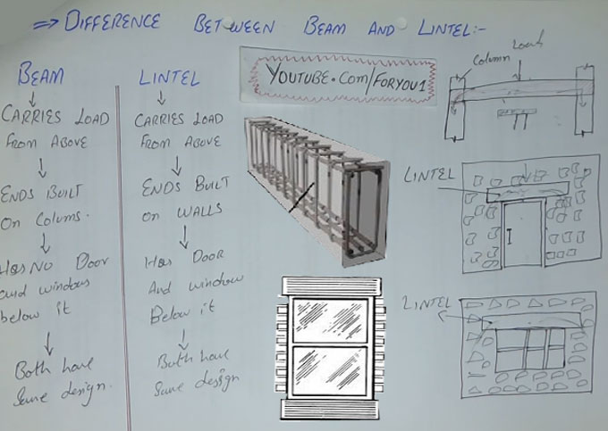
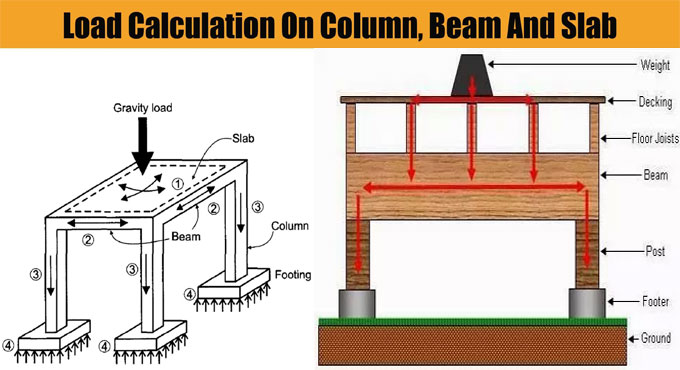
In order to work out the total load on columns, Beam and Slab, there should be clear ideas on the types of loads enforcing on the column.
Different Loads operating on Column:
1) Column Self Weight X Number of floors
2) Beams Self Weight per running meter
3) Load of walls per running meter
4) Total load on Slab (Dead load + Live load + Self weight)
Apart from above loading, the columns are also susceptible to bending moments which should be taken into consideration in the final design.
For Colomn: The Self weight of Concrete remains approx 2400 kg/m3, that is similar to 240 kN and self weight of steel is approx 8000 kg/m3.
Therefore, if we consider a column size of 230 mm x 600 mm with 1% steel and 3 meters standard height, the self weight of column is approx 1000 kg per floor that is equivalent to 10 kN.
At the time of making calculation, self weight of columns is taken as 10 to 15 kN per floor.
For Beam: Similar method is also used for making calculations of beam. Suppose, each meter of beam contains dimensions of 230 mm x 450 mm without slab thickness. Therefore, the self weight should be approx 2.5 kN per running meter.
For Walls: The Density of bricks differs among 1500 to 2000 kg per cubic meter. For a brick wall with thickness 6 inch, height 3 meter a length 1 meter. The load / running meter should be equivalent to 0.150 x 1 x 3 x 2000 = 900 kg, that is identical to 9 kN/meter. This method is useful for working out the load of brick per running meter for any brick type.
For aerated concrete blocks and autoclaved concrete blocks similar to Aerocon or Siporex, the weight per cubic meter should remain 550 to 700 kg per cubic meter.
When these blocks are utilized for construction, the wall loads for each running meter should remain as low as 4 kN/meter, the cost of the project is decreased considerably with the use of this block.
For Slab: Suppose, the slab contains thickness of 125 mm.
Therefore, self weight of each square meter of slab should be = 0.125 x 1 x 2400 = 300 kg that is identical to 3 kN.
Now, If finishing load is taken to be 1 kN per meter and superimposed live load to be 2 kN per meter. Therefore, from above data, the load of slab can be calculated as 6 to 7 kN approximately per square meter.
Factor of Safety: At the end, once the total load on a column is computed, consider the factor of safety that is very crucial for any building design for safe and convenient performance of building during its design life cycle.

Some useful tips to measure loads on column, beam and slab

~~~~~~~~~~~~~~~~~~~~~~~~
Published By
Rajib Dey
www.bimoutsourcing.com
~~~~~~~~~~~~~~~~~~~~~~~~

Tuesday, July 30, 2019

Guidelines to provide concrete cover for reinforcement in slab, footing, beam & column

Concrete cover: Concrete Cover is arranged for the reinforcement in Reinforced Cement Concrete. Cover means the spacing among the exterior surface of the concrete to the inserted reinforcement.
Benefits of arranging Concrete Cover: The purpose of covering is to provide protection against erosion. Reinforcement is susceptible to erosion and fire for atmospheric conditions. In case of improper cover erosion and cracks may occur in hardened RCC.
Covering is arranged for each and every component of the building (Slabs, Beams, footings) where the reinforcement is applied. The covering blocks are utilized to retain the reinforcement in exact position as well as providing a covering for reinforcement.
Several Types of Concrete Cover Block: Depending on the type of materials applied, the following types of covering blocks are commonly found -
1. Wooden concrete cover Block
2. Steel concrete cover block
3. PVC Block
4. Cement Masonry concrete cover block
5. Aluminium Block
6. Stones
Conditions for Concrete Cover: Covering differs based on the dimensions of the components (Slab, beam, column, footings, etc.) The conditions for arranging covering in RCC are provided below -
Condition - Covering
When the length of the item is ≤ 0.3 1 - 1" or 25mm or 0.025mWhen the length of the item remains among 0.4m to 0.5m then - 2" or 50mm or 0.050m
When the length of the item remains ≥ - 0.6m then 4" or 100mm or 0.1m
From above, the maximum concrete cover remains 0.1m or 100cm
1. Concrete Cover in Columns / Beams: The length and width of the column should be 0.5m and 0.45m. The covering for reinforcement in the column should be 0.050m from all sides and similar reinforcement should be designed accordingly. The Dimensions of Reinforcement in the column should be 0.40m and 0.35m.
Suppose the length and width of the column are 0.40 and 0.25. Covering should be equal. Consider the minimum dimension from the two dimensions i.e. 0.25. For 0.25m the covering of 0.025m should be provided. So, the covering of 0.025m is arranged in all the sides. Therefore, dimensions of reinforcement is 0.35m and 0.20m.
Total Length of Stirrup is 2x [0.35+0.20]+ 9D x 2 (hook length)
2. Concrete Cover for Slabs: Suppose, the length and width of the slab are 1.3m and 1.0m. The covering of 0.1m is arranged when the length of the bar is in excess of 0.6m. Use the same condition as mentioned. The covering of 0.1m is arranged from all the sides of the slab.
3. Concrete cover for footings: Suppose, the dimensions of Footing are 0.7m and 0.6m. To length and width of Mesh (reinforcement) utilized in footings are acquired by subtracting the cover. Use the similar principle as above. As per the condition, a concrete cover of 0.1m is subtracted from all the sides. Therefore, the dimensions of reinforcement are 0.5m and 0.4m.

Guidelines to provide concrete cover for reinforcement in slab, footing, beam & column
~~~~~~~~~~~~~~~~~~~~~~~~
Published By
Rajib Dey
www.constructioncost.co
~~~~~~~~~~~~~~~~~~~~~~~~

Tuesday, May 14, 2019

Details about concrete cover in reinforcement

Concrete cover means the minimum distance among the surface of implanted reinforcement and the exterior surface of the concrete according to ACI 130 code. The concrete cover depth is calculated with a cover meter.

The purpose of the concrete cover is to safeguard the reinforcement.

While making design of reinforced concrete structures, the reinforcement already arranged is implanted in the concrete up to a specific distance from the face of the member due to the following grounds:

• To safeguard the reinforcement against corrosion.
• To make reinforcement as a good fire resistant.
• To arrange adequate entrenched depth in order to provide necessary stress to reinforcement.


This distance is calculated in several methods and recognized with various names:

1. Clear cover: It stands for the distance from the face of the member to the most exterior face of the reinforcement along with shear or torsion Stirrups or links.

2. Nominal cover: It has similarity as clear cover though with a dissimilar name. This term is applied with the code. It belongs to the distance calculated from the face of the member to the most exterior face of the reinforcement along with Stirrups or links. It is the dimension demonstrated in drawings and detailing.

3. Effective cover: It is the distance calculated from the face of the member to the center of area of the main reinforcement i.e. the tension or compression reinforcement. It refers to the dimension generally applied for design calculations.

Effective cover = Clear cover + (Dia of Stirrups/links) + 0.5 * (Dia of main reinforcement bars).

Also,
Effective cover = Overall depth – effective depth.


At each end of reinforcing bar, concrete cover should not be under 25 mm or less than twice the diameter of the bar.

For a longitudinal reinforcing bar in a column, concrete cover should not be under 40 mm or under the diameter of such bar. In case of columns with least dimension of 20 cm or under, whose reinforcing bars do no not goes beyond 12 mm, concrete cover of 25 mm should be applied for reinforcement.

For longitudinal reinforcing bars in a beam, the concrete cover should not be under 30 mm or less than the diameter of the bar.

For tensile, compressive shear or other reinforcements in a slab or wall, the cover should not remain under 15 mm or under the diameter of such bar.

For footings and other major structural members in which the concrete is arranged directly against the ground, cover to the bottom reinforcement should remain 75 mm. If concrete is poured on a layer of lean concrete, the bottom cover should be minimized to 50 mm.

Details about concrete cover in reinforcement

Read more
~~~~~~~~~~~~~~~~~~~~~~~~
Published By
Rajib Dey
www.constructioncost.co
~~~~~~~~~~~~~~~~~~~~~~~~

Wednesday, February 8, 2017

Variation among Working stress method and Limit state method

This construction video shows the variation among working stress method and limit state method.

The basic variance among Working state method (WSM) and Limit State method (LSM) is that WSM stands for an elastic design method while LSM stands for a plastic design method.

In elastic design method, the design strength is estimated in such a manner that the stress in material is controlled with its yield limit, under which the material adheres to Hooke's law, and therefore, the word "elastic" is utilized. This method is used to produce cost-effective design of simple beam, or other structural elements where the standard for evaluating the design is stress (static). But, in case of changing the evaluation standard to other factors like fatigue stress, both the methods will give similar design. Also, WSM substantially reduces the calculation efforts.

In plastic design method the stress in material is permitted to go outside the yield limit and move into the plastic zone to attain extreme strength. Therefore, the "moment-rotation" power of beam, as for instance, is applied for creating more cost-effective design. However, because of the deployment of the non-linear zone, this method comprises laborious calculation.

Given below, some other general differences:

1) Serviceability check if LSM is necessary since after the elastic region strain is greater, it leads to more deformation, therefore a check is required.
2) LSM refers to strain based method while WSM is stress based method.
3) LSM refers to non-deterministic method while WSM is deterministic approach.
4) Partial safety factor is applied in LSM while Safety factor is applied in WSM.
5) Characteristic values (resulting from probabilistic approach) are applied in case of LSM while Average or statistic values are applied in WSM.


~~~~~~~~~~~~~~~~~~~~~
Published By
Rajib Dey
~~~~~~~~~~~~~~~~~~~~~

Tuesday, July 26, 2016

How to determine Shear Force & Bending Moment Equations for a beam

This informative construction video briefly explains how to determine equation for shear force & bending moment as well as how to sketchup their diagrams.

The shear force at a segment of a beam denotes the force that shears off the section and is procured like the algebraic sum of all forces together with the reactions functioning normal to the axis of the beam both to the left or right of the beam. As the beam is a inflexible structure, the force will be transmitted internally all along the beam. This internal force is called shear force.

Shear and bending moment diagrams belong to analytical tools applied in combination with structural analysis to facilitate accomplishing structural design by finding out the value of shear force and bending moment at a specified point of a structural element like a beam. These diagrams are used to define the type, size, and material of a structural member efficiently in a structure with the purpose of supporting a specified set of loads devoid of structural failure. Shear and moment diagrams are also useful to find out the deflection of a beam easily by applying either the moment area method or the conjugate beam method.


~~~~~~~~~~~~~~~~~~~~~
Published By
Rajib Dey
~~~~~~~~~~~~~~~~~~~~~