adsense analytic

Showing posts with label design. Show all posts

Wednesday, August 5, 2020

Design of Highway Alignment

In this post, we are examining the Importance of Highway Alignment and different elements which should have been considered in arranging the highway alignment. The Terms which we talk about here are the most significant and typically go over in highway structuring and arranging. As a structural designer, you should know about these terms. When the arrangement of road construction is chosen, the following stage to chip away at is the highway alignment.

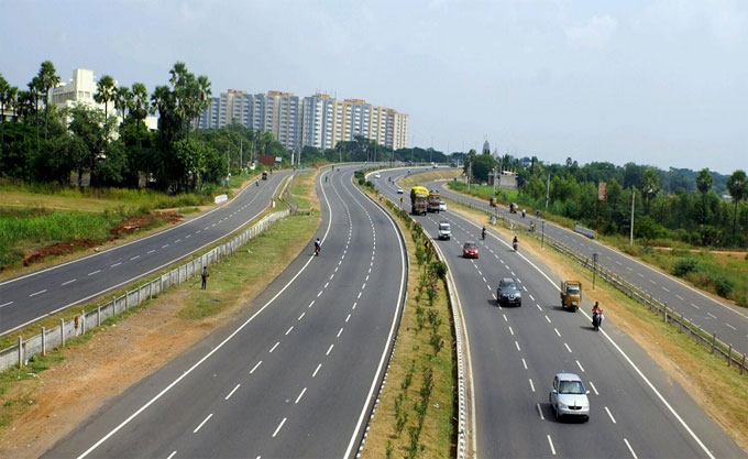
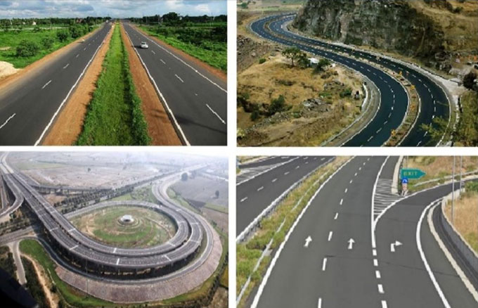
What is Highway Alignment: The situation of the focal line of the highway or the design of the arranged highway line on the ground is called Highway Alignment. Highway Alignment is for the most part stated as two sorts on Highway plans.

Horizontal Alignment: This covers the horizontal way of the road either it's straight or curved or both. Top perspective on road alignment gives horizontal alignment of the road.

Vertical Alignment: This arrangement with the inclinations, slopes and leveling of the ground. Viewpoint view or front view or side perspective on the road alignment causes you to comprehend about Vertical alignment.

Significance of Highway Alignment: Choosing the highway alignment is the most essential piece of road construction. Road construction includes a ton of land securing. When the alignment is fixed and built according to design, it is hard to change it in view of addition at the expense of connecting the area and advancement of costly structures by the roadside. A little mistake in the Highway alignment improves the expense of construction.

The perfect Highway alignment should meet the accompanying rules as follows.

1. The alignment ought to be structured so that the distance between the beginning point and the endpoint of the road ought to be short and straight with fewer curves.
2. The alignment is chosen so that it ought to be anything but difficult to build and keep up. A decent alignment ought to be direct and have less angles and slopes. To accomplish this, a little deviation in alignment is allowed.
3. The alignment ought to be viewed as just when the activity cost, introductory expense and upkeep cost is least.
4. The choice alignment ought to be sheltered during construction, particularly at banks, slopes, bumpy regions and at inclinations.

Components controlling the Highway alignment

Obligatory Points: The control focuses administering highway alignment are called obligatory focuses. These focuses choose where the alignment should pass and where the alignment ought not pass.

Design of Highway Alignment

~~~~~~~~~~~~~~~~~~~~~~~~~~
Published By
Rajib Dey
www.constructioncost.co
~~~~~~~~~~~~~~~~~~~~~~~~~~

Thursday, June 18, 2020

Twin Hospitals Built in 4 Weeks in Georgia out of Shipping Containers

China had built a speciality hospital in 10 days, and the brits did it in two weeks. It seems, America is not far behind either. And they took an ingenious approach to build the hospital.

There is a coronavirus hotspot in Albany, Georgia in the united States. And they needed a speciality hospital for the hordes of COVID-19 patients and they needed it fast. So, the Georgia Emergency Management and Homeland Security Agency (GEMA) was the first to reach out to BMarko Structures about the hospital design

Antony Kountouris, CEO, BMarko Structures, started his company almost six years ago. He believes the off-site modular construction would eventually dominate the industry. “With modular construction, you're able to do work in conjunction with your peers and your coatings while you're building the box for delivery to the site,” he said.

And in the case of this 4-week-deadline hospital building, Kountouris was able to deliver a plan within days of asking, using a special strategy: shipping containers! Shipping containers are plentiful, affordable, and useful. With 14-ga. walls that are 2 mm thick, the containers provided a solid option for a company looking for quick construction that could deliver on functionality. Over the years the container method of construction proved itself worthwhile. 

Kountouris recognized that the shipping containers might be a good way to deliver much-needed medical space to communities seeing their hospitals overrun with COVID-19 cases. “The containers made sense for the COVID-19 response,” said Kountouris, ensuring that they were immediately available for construction. He added, “The containers are ready-made. You have to build them up, but you don’t have to start from the ground up like you would with a steel or wood module.”

The goal was quite daunting. Each hospital comprises 21 containers, which has 24 patient rooms and auxiliary rooms dedicated to oxygen management; electrical distribution; data management; air exchange; and vacuum functions, which are necessary for each of the 24 head walls that are a part of the patient rooms.

However, at first Kountouris asked for eight weeks of time for a hospital. When GEMA told him they can give him four weeks only for two facilities, it pretty much quadrupled his work. Unfazed, he replied, “I guess I’ll need more space and more people, but I’ll find them.”

Georgia out of Shipping Containers

~~~~~~~~~~~~~~~~~~~~~~~~~~
Published By
Rajib Dey
www.constructioncost.co
~~~~~~~~~~~~~~~~~~~~~~~~~~

Friday, April 3, 2020

Design and analysis of Retaining Wall

This construction article presents some useful tips for designing and examining retaining wall for foundation.

Dimensions of base from stress considerations:

The base width b concerning the retaining wall must be selected carefully in order that the ratio of length of the toe slab to the base width should be maintained in such a manner that the stress p1 at the toe should not surpass the safe bearing capacity of the soil.

The topics covered:

1. Design for conventional retaining wall
2. Retaining Wall Design – Proportioning
3. Earth Pressure on Retaining Wall
4. Equivalent Fluid Method
5. Retaining Walls with backfill slope of finite distance
6. Earth Pressure on Retaining Walls with backfill Slope of finite distance
7. Stability of retaining wall
8. Check Against Overturning
9. Check Against Sliding
10. Alternatives for improving FOS against sliding


Staircase Dimensions - How to Calculate Properly

~~~~~~~~~~~~~~~~~~~~~~~~~~
Published By
Rajib Dey
www.constructioncost.co
~~~~~~~~~~~~~~~~~~~~~~~~~~

Tuesday, March 31, 2020

Different types of BBS shape codes for steel

Sami Ullah, the renowned civil engineer, presents this useful video tutorial in civil engineering youtube channel. In this video, the detail process is given for finding out the quantity of steel as well as shape codes for the steel bars.

Shape codes are considered as the basis of a proper bar bending schedule.

While going to estimate the reinforcement detailing for various members concerning a building, small bent ups and other angle detailing should be considered in the calculation to produce valid and cost-effective bar bending schedule.

It will significantly reduce the cost and wastage of reinforcement.

In beams & slabs there exist various bent ups, cuttings, and development lengths. Each and every bend and angle presented in the member is the outcome of design calculation. Therefore, these should be carefully enforced in practice.

For small projects, it is unnecessary to compute these details, just include a few more inches and work out the Bar Bending Schedule.

Different types of BBS shape codes for steel

~~~~~~~~~~~~~~~~~~~~~~~~~~
Published By
Rajib Dey
www.constructioncost.co
~~~~~~~~~~~~~~~~~~~~~~~~~~

Thursday, March 19, 2020

The Goa-Karnataka Highway Project to Start Soon

The IRB Infrastructure Developers Ltd. have announced the commissioning of the Goa-Karnataka Border Highway to Kundapur on Wednesday. The highway is to have four lanes and have a concession life of 28 years. The projected cost of the construction is Rs. 3447 crore.

One of the biggest private companies in India to build road infrastructure, the IRB has constructed over 12600 kilometers of lanes already. With impeccable reputation, they seem to be well-suited to handle this project. With this project commissioned, all the 12 projects under the company’s wing presently ongoing are going to be revenue generating.

The actual commissioning is done by the IRB Westcoast Tollway, a subsidiary of IRB Infrastructure. They have commissioned the Goa-Karnataka Border to Kundapur 4-lane highway project. Thus it will be open for vehicular traffic.

Features of the project:

Total length of serviceable road: 61.26 km
Pedestrian underpasses: 9
Vehicular underpasses: 3
Flyovers: 4
Minor bridges: 39
Major bridges: 14
Intersections with other roads: 23
Culverts and similar passes: 573
line over bridges: 3
Toll fee collection plazas: 3
Concessional life: 28 years
Estimated total cost of construction: Rs. 3,447 crore


The company chairman and managing director Virendra D Mahaiskar said, “We are happy to commission the important coast highway infrastructure link between West and South India. We believe that the project would bring the world class and safe commuting experience of the highway infrastructure in India.”

The Goa-Karnataka Highway Project to Start Soon

~~~~~~~~~~~~~~~~~~~~~~~~~~
Published By
Rajib Dey
www.constructioncost.co
~~~~~~~~~~~~~~~~~~~~~~~~~~

Monday, March 16, 2020

Contemporary 3BHK Duplex House Design

Today we will review the design of Arabella, a contemporary 3BHK duplex. It is a rather small house with a space-saving design, which puts the living area in the ground floor and the sleeping area on the first floor. The total livable area in this house is 232 square meters. On top of that, you have a roof deck.

The Arabella design is suitable to build in any plot with 176 square meters of area. The Building is attached with a one-side firewall. The front of the plot must have at least 11.5 meters of clearing.

1. Advantages of of the design
2. Modern looks
3. Suitable for urban areas
4. Suitable for seasides and mountainsides
5. Roof deck offers panoramic view of surroundings and sky


Color scheme suitable for this design: The walls should be painted a stark or mellow white, including the main wall. Accents should be painted a dark color contrasting with the walls, but not clashing contrast.

Other areas like roof bars and doors should have light earth colors like wood finish. Large aluminum framed windows should have dark gray frames and dark glasses in order to imbue more depth of field to the white walls.

Ground Floor Plan: Ground floor plan of the Arabella design consists of the living and utility area. It has: living room, dining, kitchen, common toilet and bath. Outdoors building will consist of the garage, lanai, porch, service/laundry area.

Contemporary 3BHK Duplex House Design
~~~~~~~~~~~~~~~~~~~~~~~~~~
Published By
Rajib Dey
www.constructioncost.co
~~~~~~~~~~~~~~~~~~~~~~~~~~

Saturday, February 22, 2020

Building Construction Work Sequence

A constructor needs to follow the work sequence carefully. Otherwise, the whole process of building construction might crash. Thus it is very important to maintain and follow the work sequence in building construction carefully. Let us see how it should be done properly.
1. Paper Work: The paperwork for the building needs to be finished even before the work actually begins. This includes:-
a. Preparation of drawings and diagrams
b. Material and construction cost estimation
c. Labor costs and contingency measures
d. Approval of design from local development authority
e. Any other legal work that may be necessary
2. Layout Marking: The plan boundaries need to be marked on the ground. Only the approved plan should be marked down. The ground inside and outside the site should be cleaned of any undesirable elements. Accurate dimensions and orientations must be followed while marking down the layout.
3. Excavation Work: The foundations of the building need to be placed under the ground level, onto a solid bed. For this, much excavation work needs to be done on site according to design. The wall foundations and column foundations may require different types of foundations. For this reason, different amounts of excavation may need to be done.Suitable machinery like dozers need to be used for large scale excavation. Not only that, you need to carry off the excavated earth to a suitable location as well.
Building Construction Work Sequence
~~~~~~~~~~~~~~~~~~~~~~~~~~
Published By
Rajib Dey
www.constructioncost.co
~~~~~~~~~~~~~~~~~~~~~~~~~~

Friday, February 14, 2020

What are Shear Keys and How to Use Them

A building and structure has to bear not only vertical loads, but also lateral loads. This can occur due to many design or natural reasons. To counteract this lateral load, Shear Keys are used. Let us see today what exactly are shear keys and how can you use them in your construction.
A building can face a lot of lateral load due to many reasons. Some of these include earthquake loads, sliding forces, water pressure, wind pressure etc. This often occurs with bridges, retaining walls, basements, extremely tall buildings, precast buildings and culverts, masonry walls where seismic activity is stronger, and steel columns and piers.
Shear keys can be constructed by concrete in precast buildings, and of steel in steel structures. Sometimes, steel reinforcements are made to play the part of shear keys as well. They improve the lateral stability of a building.
Placement of Shear Keys: Where the shear keys will be placed differs a lot depending upon the structure they need to support. Let us discuss them below.
Bridges: In small to medium bridge structures, shear keys are placed in the abutments of the bridge. This provides lateral transverse support to the structure above during sidewise movement.
During an earthquake or similar strong lateral force application, the shear keys act as a sacrifice. Therefore, the strong seismic forces are prevented from entering the abutment piles.
They act better when they are placed on the outer side of the bridge. However, this makes them difficult to inspect or repair.
Retaining Walls: You should place shear keys at the base of retaining walls, just beneath the stem. This prevents sliding of the base during strong lateral force application.
The shear keys placed beneath the wall must be nearly twice in width than their depth for the best performance. Generally, they are 508mm by 381 mm, respectively.
What are Shear Keys and How to Use Them
~~~~~~~~~~~~~~~~~~~~~~~~~~
Published By
Rajib Dey
www.constructioncost.co
~~~~~~~~~~~~~~~~~~~~~~~~~~

Monday, February 10, 2020

Using Light Gauge Steel Frames in Construction

There is a new construction method on the market, and it is quite cool. Called the Light Gauge Steel Frame Construction, it is successfully replacing the standard wood frame construction method. This innovative method is being widely accepted in many building designs and construction aspects.
The Light Gauge Steel Frames offer several advantages. Some of them are design flexibility, strength, sustainability, buildability, etc. This makes Light Gauge Steel Frames easier to build and much safer too. Not only that, it is also faster to build. Word to the wise, though - the light steel frame is susceptible to fire, so fire protection coating needs to be provided.
Based on ASTM standard A1003, Light Gauge Steel Frames are manufactured from structural steel sheets. These sheets are formed into ‘C’ ‘Z’ and ‘S’ shapes. This makes the structure strong and able to support heavy loads. It is also called cold formed steel. This is because of the process by which it is manufactured.
This added strength and flexibility leads Light Gauge Steel Frames to support increased spans. They can be shaped into custom openings. Moreover, they can support many different types of external facade treatments. This sheer versatility is making the Light Gauge Steel Frames very popular among modern constructors.
One thing to be noted about Light Gauge Steel Frames is they are much more susceptible to corrosion effects than standard wooden frames. For this reason, they have to be provided with zinc, aluminum or combo coatings to make them corrosion-resistant over long periods.
Using Light Gauge Steel Frames in Construction
~~~~~~~~~~~~~~~~~~~~~~~~~~
Published By
Rajib Dey
www.constructioncost.co
~~~~~~~~~~~~~~~~~~~~~~~~~~

Friday, February 7, 2020

How to avoid Honeycombing in RCC Structures

Definition of a honeycombing: Honeycombing refers to a structural fault in a RCC Structure. Honeycombed surface is the areas of the concrete surface where the coarse aggregate are eminently observable.
If precaution is not taken for honeycombed surface, the RCC structure fails to achieve optimal performance according to its design (structurally weak). Besides, it also lets damaging agents like contaminated water and air entering through the produced voids which can impact the strength of structure considerably.
Causes for Honeycombing: Honeycombing in RCC Structure is happened because of the following reasons -
1. Concrete mix is not homogenous.
2. The applicability of concrete is inadequate and not matched with its placement need.
3. Inadequate compaction to concrete.
4. Concrete flow is not dispersed to all corner due to steel congestion.
5. Concrete is set afore time prior to placing.
6. High free fall of concrete, at the time of pouring
7. Form work is not waterproof or inflexible.
8. Incorrect detailing and/or fixing of steel
How Honeycombing in Concrete can be avoided?
Check concrete production/cohesiveness from time to time to organize all concrete batches.
Tip: If it is possible to create ?ball? from the fresh concrete, a cohesive concrete mix is produced.
Concrete workability should tally with the placement need. As for example, a lightly reinforced column should contain 75mm slump, a heavily reinforced column may require 150mm slump.
Make sure that the compaction of placed concrete is perfect, vibrators should have been detached as big air bubbles stops to come out (over vibration can lead to bleeding). Various sizes (25mm, 40mm, and 60mm) of vibrator needle should have been utilized according to RCC sections.
How to avoid Honeycombing In RCC Structures
~~~~~~~~~~~~~~~~~~~~~~~~~~
Published By
Rajib Dey
www.constructioncost.co
~~~~~~~~~~~~~~~~~~~~~~~~~~

Friday, December 13, 2019

Five Reasons Why Off-site Modular Construction is the New Favorite

What is Off-site Modular Construction
Up until the last decade, we have always known construction business is to be conducted on project site. However, with the advent of technology, a new method of building has come up. This is called Off-site Modular Construction, and it is shaking the construction industry at the roots.
In this process, portions of a building are constructed in remote factories or fields that are specifically set up for that purpose. They are built using the same design and materials - but since they are being built in a factory for that express purpose, the construction takes about half the time. These “modules” are then carried off to the project site and are assembled there to reflect the original design of the entire project.
Growth in Modular Construction Business
There has been an increased demand for off-site modular construction, ever since the construction industry has rebounded up since 2013. Experts project that the market has progressed by 26% between 2014 to 2017.
An estimate is that the projected growth for the period 2018 to 2020 is by 4% every year. Such promising verticals can be associated with the resurgence in sectors such as education, offices, and retail. It is also a gift from with increased market for locality accommodation on infrastructure projects.
Architects, developers, and constructors are all gradually becoming aware of the plethora of benefits offered by technological innovations associated with the modular construction industry. From hotels, retail, offices, public buildings, apartment blocs to simple homes - all sorts of construction projects can be assembled with offsite modular structures.
This method of building is a favorable alternative to regular on-site construction, and it is durable and cost-effective. The main reason for that is the offsite modular building offers great quality and flexibility. It is also faster to finish the project with fewer expenses. Also, when it comes to counting the environmental impact and guaranteeing sustainability, there is no match for off-site construction methods.
Five Reasons Why Off-site Modular Construction is the New Favorite

~~~~~~~~~~~~~~~~~~~~~~~~~~
Published By
Rajib Dey
www.constructioncost.co
~~~~~~~~~~~~~~~~~~~~~~~~~~

Wednesday, October 9, 2019

Some useful tips to design a T-beam with the use of limit state method

This construction video briefly describes how to create the design of t-beam with the use of limit state method.
A T-beam (or tee beam) is applied in construction extensively. It is a structural element developed with reinforced concrete, wood or metal. It contains a t-shaped cross section that is formed by a stem and a flange of reinforced concrete or rolled metal.
The top of the t-shaped cross section acts as a flange or compression member in withstanding compressive stresses. The web (vertical section) of the beam underneath the compression flange contributes to withstand shear stress and offer better separation for the coupled forces of bending.
A T-beam has the capacity to tolerate large loads by providing resistance in the beam or by internal reinforcements. It operates similar to singly reinforced beam.
In order to enhance the structural strength of a T-beam, just utilize an inverted T-beam together with a floor slab or bridge deck linking the tops of the beams. If it is accomplished perfectly, the slab performs as the compression flange.

Some useful tips to design a T-beam with the use of limit state method
~~~~~~~~~~~~~~~~~~~~~~~~~~
Published By
Rajib Dey
www.constructioncost.co
~~~~~~~~~~~~~~~~~~~~~~~~~~

Wednesday, August 28, 2019

Advantages & Disadvantages of Flat Slab

Normal process of design and construction is to support the slabs with beams and support the beams with column. It is known as beam-slab construction.
The beams help in minimizing the existing net clear ceiling height. Often, in warehouses, offices and public halls, the slabs are used as a substitute of beams and they are directly supported with columns. These types of slabs are known as flat slabs.
A flat slab stands for a one-way or two-way system with solidities in the slab at the columns and load bearing walls are known as ‘drop panels’ Drop panels function as T-beams over the supports. They raise the shear strength and the rigidity of the floor system against vertical loads, thus the economical span range becomes greater.
Normally, the height of drop panels remains about two times the height of slab. The plan dimensions of the drop panels are a minimum of 1/3 of the distance in the direction being considered, normally rounded to the nearest 100 mm.
Flat Slabs are useful for most of the construction and for irregular column layouts like floors having curved shapes and ramps etc.
Types of Flat Slab Construction - Following types of flat slabs are commonly used in construction:
1. Simple flat slab
2. Flat slab with drop panels
3. Flat slab with column heads
4. Flat slab with both drop panels and column heads
The major features of a flat slab floor are a flat soffit, simple formwork and smooth construction. The economical span ‘L’ of a reinforced concrete flat slab is roughly D x 28 for simply supported, D x 32 for an end span and D x 36 for an interior span. Pre-stressing the slab raises the economical span to D x 35, D x 40 and D x 45 respectively, where D stands for the depth of the slab without the drop panel.
Benefits and Drawbacks of Flat Slabs
Benefits:
• Easy formwork
• No beams—streamlining under-floor services outside the drops
• Least structural depth
• Normally, shear reinforcement is not necessary at the columns.
• Saving in the height of the building
• Construction time is reduced
• Application of prefabricated welded mesh
Drawbacks:
• Medium extents
• Normally not ideal for supporting brittle (masonry) partitions
• Drop panels may obstruct with larger mechanical ducting
• Vertical penetrations should circumvent area around columns
• For reinforced flat slabs, deflection at the middle strip becomes important.
Advantages & Disadvantages of Flat Slab
~~~~~~~~~~~~~~~~~~~~~~~~~~
Published By
Rajib Dey
www.constructioncost.co
~~~~~~~~~~~~~~~~~~~~~~~~~~

Monday, August 26, 2019

Some useful guidelines for RCC slab design

In this exclusive civil engineering tutorial, you will get some useful guidelines for designing any RCC slab.
A) Effective span of slab – It should be least of the two
1) L = clear span + d (effective depth)
2) L = Center to center spacing among the support
B) Depth of slab: The depth of slab is influenced by bending moment and deflection criterion. The trail depth is achieved with the following :-
Effective depth d = Span/((L/d) Basic x modification factor)
To get modification factor, the percentage of steel for slab is taken from 0.2 to 0.5.
The effective depth d of two slabs is also taken as cl.24.1,IS 456 on the condition that short span is 3.5m and loading class is <3.5KN/m2.
Categories of supports: Fe-250 – L/35, Fe-415 – L/28
Continuous support: Fe-250 – L/40, Fe-415 – L/32
The following thumb rules are commonly applied :-
One way slab d = (L/22) to (L/28). Two way simply supported slab d = (L/20) to (L/30). Two way restrained slab d = (L/30) to (L/32)
Load On Slab: The load on slab contains dead load, floor finish and live load. The loads are measured according to unit area (load/m2).
Dead Load = D x 25 kN/m2 (Here D denotes thickness of slab in m). Floor finish (taken as) = 1 to 2 kN/m2. Live load (taken as) = 3 to 5 kN/m2 (based on the occupancy of the building)
Nominal Cover
For mild exposure – 20 mm
For moderate exposure – 30 mm
When the diameter of bar does not go beyond 12 mm or cover is decreased by 5 mm. For main reinforcement up to 12 mm diameter bar and for mild exposure, the nominal cover is 15 mm.
Least reinforcement: The reinforcement in either direction in slab should not remain under :-
0.15% of the total cross sectional area for Fe-250 steel. 0.12% of the total cross sectional area for Fe-415 & Fe-500 steel
Distance of bar: The maximum distance of bars should not surpass. Main steel – 3d or 300 mm which is lower. Distribution steel – 5d or 450 mm whichever is lesser
Here, d denotes the effective depth of slab. The least clear spacing of bars should not be under 75 mm (desirably 100 mm). Highest diameter of bar. The highest diameter of bar should not go over D/8, here D denotes the total thickness of slab.
Some useful guidelines for RCC slab design

~~~~~~~~~~~~~~~~~~~~~~~~~~
Published By
Rajib Dey
www.constructioncost.co
~~~~~~~~~~~~~~~~~~~~~~~~~~

Friday, August 23, 2019

Details about structural and non structural defects in buildings

Concrete has diversified nature. It casts in place by including or excluding reinforcement. It is also precast or pre-stressed to attain necessary strength. For this purpose, there should be adequate knowledge on the behavior and constituents based on which the concrete is produced.
There should not be any type of laxity in any of its phase like placement, design & maintenance as these can create deterioration and resist concrete to accomplish its proposed functions. Given below, some vital factors which can weaken the quality of concrete:
1. Accidental loading
2. Chemical reaction like sulfate attack, alkali carbonate reactions, alkali silica reactions etc
3. Erosion of steel reinforcement
4. Inferior construction detailing
5. Erosion
6. Freezing and Thawing
7. Shrinkage
8. Settlement
9. Fire and weathering
Flaws in Building Design: Due to deficient structural design, the concrete is uncovered to flexural and shearing stresses and as a result spalling and cracking of concrete are developed. Any sudden modification in cross section of any member can result in raising the stress concentration in that member that leads to cracking of concrete.
Deflection is considered as one of the significant part in structural design. If there exist any issue in its consideration throughout design, that can produce cracking of concrete. Insufficient arrangement of drainage and expansion joints throughout the design also leads to deterioration and spalling of concrete.
Flaws During Construction: Flaws throughout building construction vary from inappropriate mixing, placing and curing of concrete. Detachment of shoring & formwork can also produces cracks in concrete.
When extra water is provided in concrete to enhance the workability of concrete, the water cement ratio is raised significantly and it can reduce the strength of concrete. Inappropriate alignment of formwork produces corrosion in concrete.
Structural Defects in Building Construction - The following structural defects are found in buildings:
1. Cracks in foundation (substructure)
2. Cracks in floors and slabs (superstructure)
3. Cracks in Walls (superstructure)
These above defects are occurred due to the following factors:
1. Inappropriate soil analysis
2. Inappropriate site selection
3. Application of defective materials
4. Inferior work
These structural issues can be resolved with perfect design and planning.
Non Structural Defects in Building Construction - The following non structural defects are common in buildings:
1. Defects in brick work
2. Dampness in old structures
3. Defects in plaster works
So, it is found that minimum design and construction defects lead to minor cracking or spalling which can weaken the concrete and result in collapsing of the structure. To get rid of these issues, proper care and attention should be taken in designing, detailing and construction of concrete structure.
Details about structural and non structural defects in buildings
~~~~~~~~~~~~~~~~~~~~~~~~
Published By
Rajib Dey
www.constructioncost.co
~~~~~~~~~~~~~~~~~~~~~~~~

Monday, August 5, 2019

Factor of safety for soil bearing capacity

Factors of safety for bearing capacity refers to a value that is based on the basis of the type of soil, method of exploration, level of uncertainty in soil, significance of structure and outcomes of failure, and probability of design load proceeding.
So, it creates adequate space to adapt uncertainties and potential over loading throughout the duration of the structure and its foundation through the cutback of ultimate bearing capacity of soil to permissible bearing capacity.
The permissible bearing capacity is measured by dividing ultimate bearing capacity with factor of safety. Normally, a factor of safety of (3) is presumed for bearing capacity calculations, if not mentioned for bearing capacity problems.
Bearing capacity means the strength of soil to bear the pressure securely that is provided on the soil from any engineered structure devoid of experience a shear failure with accompanying large settlements. Applying a bearing pressure that is secured with regards to failure does not guarantee that settlement of the foundation will remain inside tolerable ranges.
So, settlement analysis should normally be accomplished since most structures are sensitive to extreme settlement.
In the following table, you will get the standard factor of safety for bearing capacity calculation in different conditions. These factors of safeties are conservative and normally limit settlement to suitable values, but economy may be abandoned in some cases.
Factor of safety chosen for design is based on the extent of information obtainable on subsoil characteristics and their variability. A detailed and wide-ranging subsoil investigation may allow use of smaller factor of safety.

Factor of safety for soil bearing capacity

~~~~~~~~~~~~~~~~~~~~~~~~
Published By
Rajib Dey
www.constructioncost.co
~~~~~~~~~~~~~~~~~~~~~~~~

Friday, July 12, 2019

Sample quotation for constructing an indoor badminton court

In this civil engineering article, you will get a sample quotation with quantities of construction material to design and develop an indoor badminton court.
SPECIFICATIONS: MAIN FEATURES –
• The structure should contain a basement height of 1’0” from Natural ground level.
• Footing pit size 4’x4’x6’-10mm dia @8” c/c main, 8mm dia @8” c/c alternate.
• Column size – 9”x9” (6 nos 16mm dia and stirrups 8mm dia @8” c/c)
• Plinth size – 9”x9” (4nos 12mm dia main reinforcement and stirrups 8mm dia @ 8” c/c)
• Brickwork should be done with superior quality chamber bricks containing cement mortar in 1:6.
• Basement height 2’-0” Basement inside filling with soil. Over the soil PCC is laid with 1:4:8 with 40mm blue metal.
• Plastering with cement mortar 1:4 exterior wall.
• One coat of white cement and two coats of Asian exterior emulsion should be applied.
• Grano flooring with blue metal chips over PCC in the basement.
THE FOLLOWING MATERIALS ARE UTILIZED:–
• CEMENT: Dalmia/Ultratech/Ramco
• BRICKS: Chamber
• STEEL: ISI
• SHEET: JSW CCGL0.47
• PAINT: ASIAN Paint
Total Area of the Building is supposed to be 54’-0” x 54’-0” = 2916.sq.ft.
Subject: Metal Roofing Shed
‘A’ Truss Length x Width: 58’ Feet x 54’ Feet =3132.Sq. Ft
CLADDING WORK (27’x54’) + (27’x54’) + (30’x54’) + (30’x54’) =6156. Sq. ft
Sub: Fabrication and construction of traditional steel structure with Cooler coated Galvalume.
Columns: Delivery and installation of 12 Numers.150×100 Columns (MS I BEAM Height 32’ Feet) Columns Base Plates should have 20 mm thickness 300 mmX300mm & Columns top Plates should have 8 mm thickness.
Base foundation 25 mm 1’5’Feet 48 Numbers
Columns Bracing Support ( X 4 Numbers)
A Type Trusses: Delivery and installation of of 4 Numbers. Trusses 54.0” Feet span formed 50X50mm MS Square Pipe Bottom Rafter as 50X50mm MS pipe with inner cross 30X30 Straight as 30X30 mm pipes medium (ISI 2mm thickness) Lighting Support 1 No Inclusive.
Paint Works: One coat of premier & two coats of enamel paint.
Roof Sheet: Color coated Galvalume CCGL JSW sheet (0.47mm) and its accessories.
Purlin > 60×40 (ISI 2mm thickness) Square Tube purlin.(1000+1300=1Numbers)
To get more details, click on the following link www.onlinecivilforum.com
Sample quotation for constructing an indoor badminton court

~~~~~~~~~~~~~~~~~~~~~~~~
Published By
Rajib Dey
www.constructioncost.co
~~~~~~~~~~~~~~~~~~~~~~~~

Tuesday, July 2, 2019

Benefits of I-beams in construction

Hot-rolled steel beam having I-shaped cross section, and tapered flanges closer than wide flanged beam is known as I-beam.
I Beam contains one vertical plane and two horizontal planes or flanges which develop 'I' or 'H' structure. The vertical plane withstands the shear stress , whereas horizontal planes withstand the bending movement. I Beam is majorly utilized in construction industry like construction of manufacturing plants, multi-story buildings etc.
I-beam is frequently applied as important support trusses, or the primary framework, in buildings. Steel I beams retain structure’s integrity with persistent strength and support. The extreme power of I beams minimizes the requirement for several support structures and as a result huge time and money is saved. The stability of the structure is improved considerably.
Some vital jargons of I-Beam:
1. Flange thickness: Top and bottom horizontal plate-like segments of an I-beam are known as flange. The density of the flanges is defined as the flange thickness.
2. Flange width: The width of the flanges is known as flange width.
3. Beam depth: The height among the top and bottom surface of the steel I beam is termed as beam depth.
4. Web thickness: The vertical segment of steel I beam is known as web, and the thickness of the web is termed as web thickness.
5. Fillet radius: The curved section, where the changeover among the web and flange occurs is known as a fillet. The radius of the fillet is defined as the fillet radius.
A properly sized I Beam can be chosen on the basis of the following criterion :-
The entire method of choosing the proper size of the I beam is dependent on the basic mechanical design calculations as given below:
1. The first input necessary belongs to the steel I beam load specifications or loading details on the steel I beam.
2. Draw bending moment diagram for the specified loads and get the value of maximum bending moments (suppose M) that the steel I beam is likely to experience.
3. Select an exact size of steel I beam from a standard I beam table.
4. Determine the area moment of inertia (suppose I) of the selected steel I beam.
5. Obtain the beam depth (suppose d) of the selected steel I beam.
6. The stress developed (f) in the beam can be measured with the formula given below :
f/(d/2)=M/ I
f denotes the bending stress.
M denotes the moment at the neutral axis.
y denotes the perpendicular distance to the neutral axis.
I denotes the area moment of inertia about the neutral axis x.
7. Compare the calculated value of the bending stress with the yield stress of the steel with the purpose of verifying the safety factor of your design.
The structural design will be perfect when the size of the I-beam is accurate. The method described above is dependent on static I beam load specifications. In case where dynamic loads are concerned, it is necessary to apply FEA tools like ANSYS, Pro Mechanica, etc.
Benefits of I-beams in construction

~~~~~~~~~~~~~~~~~~~~~~~~
Published By
Rajib Dey
www.constructioncost.co
~~~~~~~~~~~~~~~~~~~~~~~~