adsense analytic

Showing posts with label Foundation. Show all posts

Thursday, July 23, 2020

The Good and Bad of Precast Piles

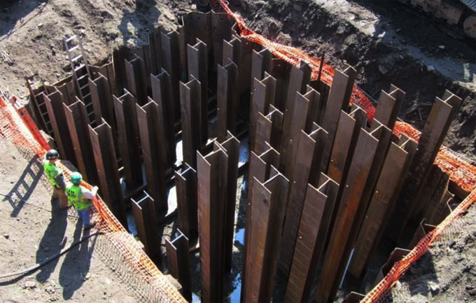
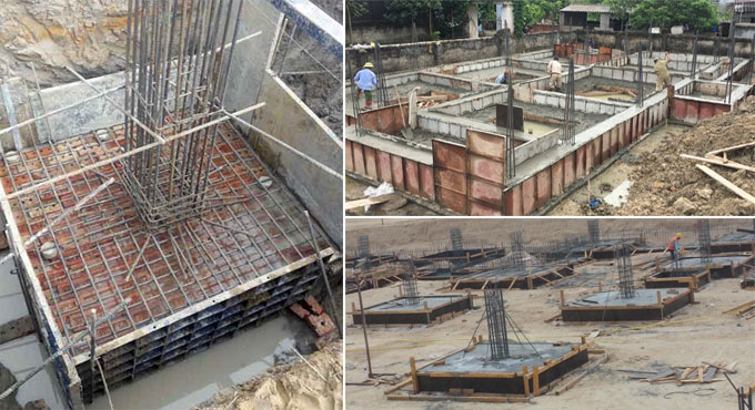
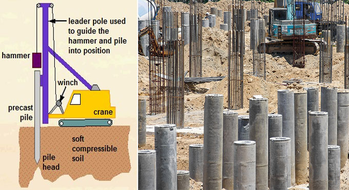
The most common type of them, a precast concrete pile is a deep foundation used to transfer loads from a upper, soft layer of soil to a hardar, capable lower layer. They can be rectangular, square, round or polygonal in shape. Extra reinforcements are provided in the concrete so as to provide support for the forces received before the instalent.

The precast concrete piles are constructed in a casting yard. Then they are transported to the required location and installed as necessary.

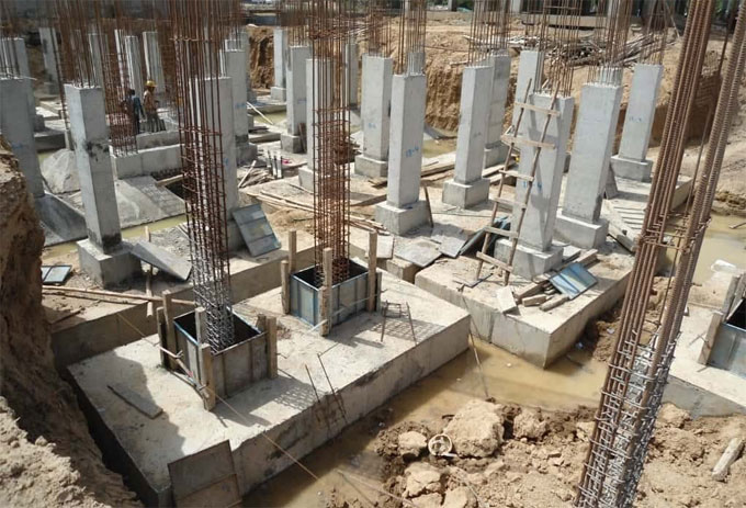
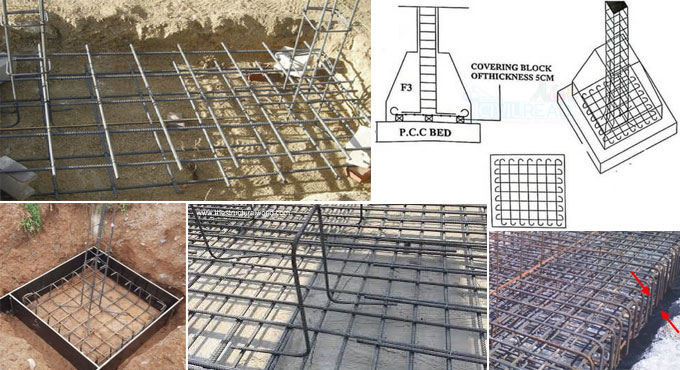
They are constructed by pouring the concrete in a conventional reinforcement cage. This has several steel bars in horizontal and vertical positions, held together by individual or spiral ties.

Types of Precast Concrete Piles

There are two main categories into which we can divide:

1. Driven Precast Concrete Piles

It is precast in a construction yard and then hammered into the soft ground at the target location. At most they can go up to 40 feet deep.

2. Bored Precast Concrete Piles

After they are made in the construction yard, they are transferred to the target location. The location already has boreholes for the piles; they are just lowered into these holes. Any space remaining between the bore hole and the pile is grouted.

Difference between the Driven and Bored Precast Concrete Piles

1. Bored piles are better in urban locations since they avoid the noise and vibrations caused by vibrators.
2. The bore hole can be as deep as necessary, or as deep as the machinery can go. Unlike driven piles, the bore piles have no depth limit.
3. Driven piles can be established quickly.
4. Driven piles can be easily used underwater.


The Good and Bad of Precast Piles

~~~~~~~~~~~~~~~~~~~~~~~~~~
Published By
Rajib Dey
www.constructioncost.co

~~~~~~~~~~~~~~~~~~~~~~~~~~

Monday, June 29, 2020

Steel Pile Foundations


Precast piles and driven cast in piles utilize steel pipes. On account of precast or completely performed piles, there are two groupings, for example, empty little removal piles and solid piles. The empty little relocation piles utilize steel pipes when steel pile foundation is recommended. With regards to solid piles, steel H-piles are utilized.

On account of driven cast set up piles the fundamental arrangement is solid cylinder steel tube. If there should arise an occurrence of steel tubes, we utilize closed ended cylinder and open-ended cylinders.

Usually utilized steel piles are moved steel H area piles or pipe piles. The pipe piles have either an open or a closed end that is driven into the ground. I-segment or wide rib piles can likewise be utilized as pile foundation.

The H-sections are favored progressively over I-sections, as the H-segment has the same thickness for the web and the spine. On account of the I area, the thickness of the web is less contrasted with its spine thickness.

In the event that Q is the permissible auxiliary limit, A being the cross – sectional territory of the steel and the suitable worry of the steel given by fs, then:

Qall = A x fs

During the geotechnical examination the plan quality is resolved as Qdesign and this must be inside the Qall.

Types of Steel Pile Foundations

By and large, the steel piles can be sorted into the following categories: Screw Piles, Circle Piles, H-piles

Steel Pile Foundations

~~~~~~~~~~~~~~~~~~~~~~~~~~
Published By
Rajib Dey
www.constructioncost.co
~~~~~~~~~~~~~~~~~~~~~~~~~~

Tuesday, June 23, 2020

Dust and Debris Affecting Healthcare Construction: Preventive Guide Released

One of the several healthcare providers for construction workers, the University of Virginia Health System, has released an outline for infection control policies and procedures on Friday. This was done as an effort to minimize the impact of construction project environments on the health of the building workers present on site most of the time. 

This system of strict health observation required training and following guidelines to a dot. These guidelines are to be followed by the workers on the field during the construction process. The strictness and methods in the guide may vary depending upon the risk level of the construction worker doing a specific job.

The gist of the guidelines are counted out as follows.
  1. Use negative pressure systems monitored with a continuous-read negative air pressure monitor, smoke test with daily log or handheld manometer with daily log.
  2. Wait for patients to be removed before work begins in certain areas.
  3. Replace displaced ceiling tiles.
  4. Cleanup after work is complete by either wiping down the area or by using a HEPA ​(high-efficiency particulate air) vacuum.
  5. Use approved ICRA (Infection Control Risk Assessment) containment barriers.
  6. Control dust while cutting using water mist, a HEPA vacuum or other effective measures.
  7. Seal unused doors with painters' tape.
  8. Use dust control mats and all points of access.
  9. Transport construction waste out of the work area using clean containers with hard covers.
  10. Isolate the HVAC system in areas where work is going on to prevent contamination of the ducts system.
Isolate the HVAC system

~~~~~~~~~~~~~~~~~~~~~~~~~~
Published By
Rajib Dey
www.constructioncost.co
~~~~~~~~~~~~~~~~~~~~~~~~~~

Wednesday, June 10, 2020

Earthquake Prevention in Construction Industry of India

Earthquakes are among the most devastating of nature’s curses, more scary than anything else because you almost never see it coming. Any country that goes through frequent quakes tries hard to find the solution. India is no exception either. Today, we will look into what is the situation about earthquake prevention in India.

Sitting right on top of one of the major fault lines in the world, the indian subcontinent suffers some of the greatest earthquakes. Those devastating seismic activities in the last century have motivated us to look into scientific solutions to earthquakes. This led to the creation of the first building codes specifically for earthquake resistant housing, in 1935, which were compounded with strengthening guides in 1941.

The Seismic Hazard

Most of the matter inside Earth is molten rock. Lava, that is. This molten sea has currents in it like the sea above, only slower, but just as sure. The hard crust of the earth floats on top of this lava ball. And the plates of the crust move with the lava flow underneath.

The problem is that this movement is not uniform across the world. Some plates move faster in one place and slower in another side. This causes friction and collision between plates. Indeed, one such monstrous collision is what gave birth to the Himalayas. Which incredibly is still going on.

And these frictions are exactly what causes the earthquakes.

As I said above, the worst thing about earthquakes is their unpredictability. We know the geological fault lines, yes, but we have woefully few data about the movement along the lines. So, we get to make next to no prediction about seismic activity, and their magnitude. 

Earthquake Prevention in Construction Industry of India

~~~~~~~~~~~~~~~~~~~~~~~~~~
Published By
Rajib Dey
www.constructioncost.co
~~~~~~~~~~~~~~~~~~~~~~~~~~

Friday, April 3, 2020

Design and analysis of Retaining Wall

This construction article presents some useful tips for designing and examining retaining wall for foundation.

Dimensions of base from stress considerations:

The base width b concerning the retaining wall must be selected carefully in order that the ratio of length of the toe slab to the base width should be maintained in such a manner that the stress p1 at the toe should not surpass the safe bearing capacity of the soil.

The topics covered:

1. Design for conventional retaining wall
2. Retaining Wall Design – Proportioning
3. Earth Pressure on Retaining Wall
4. Equivalent Fluid Method
5. Retaining Walls with backfill slope of finite distance
6. Earth Pressure on Retaining Walls with backfill Slope of finite distance
7. Stability of retaining wall
8. Check Against Overturning
9. Check Against Sliding
10. Alternatives for improving FOS against sliding


Staircase Dimensions - How to Calculate Properly

~~~~~~~~~~~~~~~~~~~~~~~~~~
Published By
Rajib Dey
www.constructioncost.co
~~~~~~~~~~~~~~~~~~~~~~~~~~

Friday, March 13, 2020

Minimum Foundation Depth for Houses

The foundation of a house is what holds the structure up, carries its entire weight. When you try to design a new building, you must consider how deep the foundation should be in order to properly support the building. This is called the foundation depth. It is measured by the vertical distance between the footing and the natural ground surface.
Expansive Soil: One thing to be kept in mind here that light soil has expansive properties. Due to wet and dry weathers, the soil can inflate and condense accordingly. This changes the effective natural ground surface level.
As a rule of thumb, foundations are placed under this level of soil, where such changes do not occur. That is about a meter in depth, in most cases.
However, this can be significantly higher if you have expansive soil or black cotton soil on site. This type of soil can take a load of 200-300 kpa only. Any more and the building will settle.
Groundwater Under Soil: Also, another thing to be kept in mind when deciding the minimum foundation depth is the presence of water under the ground. If the groundwater table is close to the foundation, then the soil under the foundation can flow around.
Water seeps up into the soil and makes it weak. To resist this, the bottom of the footing should be placed at a deep enough place where groundwater does not seep into the soil any more.
Cold Regions: Frost changes the nature of soil. It heaves the soil upward and that may create cavities underground. For this reason, in cold regions where snowing and/or ground frosts are normal, the foundations for outside columns or walls should be placed below the level down to which frost can affect the soil.
In the northern US, this can be as deep as 1.5 meters. Further, if the internal walls are heated, then the outer walls would require a deeper foundation so that the heat does not alter the soil properties.
Minimum Foundation Depth for Houses
~~~~~~~~~~~~~~~~~~~~~~~~~~
Published By
Rajib Dey
www.constructioncost.co
~~~~~~~~~~~~~~~~~~~~~~~~~~

Thursday, March 12, 2020

The four types of Shallow Foundation

Shallow foundation is applied in cases where we can find good load-bearing soil at a rather low depth. The foundation depth must meet the safety requirements of the breakdown. That is, after the application of load, the complete structure settlement will be within acceptable limits.
We can use the following four types of shallow foundations: Spread Footing, Combined Footing, Raft Foundation and Ring Foundation.
1. Spread Foundation: You need to spread the load from the column or wall to a larger area, you should use Spread Foundation. The width of the footing area is much wider than the wall or column.
The spread footing that is used to support a wall is called a wall footing or continuous footing. The top of the footing may be stepped or tapered, increasing the width gradually from wall or column to the base. They are of the following types:
a) Strip Footing: This primitive type of footing has been conventionally used in most constructions historically, before more modern inventions. They are mostly made of stones, masonry or concrete. The strip footing that is constructed of stone blocks generally has a stepped top. In modern days, however, the use of strip footing has become next to obsolete. Only in some light loading residential construction is strip footing still used.
b) Isolated Footing: When you provide footings under columns separately in a framed structure, it is called Isolated footing, pad footing or column footing.
In most cases, square footings are used under columns. However, space restrictions may force you to use rectangular footings. In case of circular columns, circular footings may be used, though it is not common. It may be used in special circumstances where construction work is difficult, or the load has to be dispersed very equally.
2. Combined Footing: When two columns are too close to make separate footings for each, then their footings are combined. These may be of the following three types:
a) Rectangular footing: These are the most common types of combined footing. It’s basically two square footings constructed together. This is used when each column is bearing the same load and of the same size.
The four types of Shallow Foundation
~~~~~~~~~~~~~~~~~~~~~~~~~~
Published By
Rajib Dey
www.constructioncost.co
~~~~~~~~~~~~~~~~~~~~~~~~~~

Wednesday, February 26, 2020

Types of Foundations in Construction Industry

Today, we shall talk about the common sorts of foundations in buildings. Generally, all foundations are divided into 2 categories: shallow and deep. The words ‘shallow’ and ‘deep’ check with the depth of soil during which the inspiration is created.
Shallow foundations may be created in depths of as very little as 3 feet, whereas deep foundations may be created at depths of sixty – 200 feet. Shallow foundations are used for little, lightweight buildings, while deep ones are for giant, serious buildings. The following sorts of Foundations In Building Construction may be elaborated below.
Raft or Mat Foundations: Raft Foundations, conjointly referred to as Mat Foundations, are most frequently used once basements are to be made. In a raft, the complete basement floor block serves as the foundation; the burden of the building is unfold equally over the entire footprint of the building. it's referred to as a raft as a result of the building is sort of a vessel that ‘floats’ in an exceedingly ocean of soil.
Mat Foundations are used wherever the soil is weak, and thus building hundreds have to be compelled to meet an oversized space, or wherever columns are closely spaced, which suggests that if individual footings were used, they might hit one another.
Shallow Foundations: Shallow foundations are referred to as unfold footings or open footings. The ‘open’ refers to the very fact that the foundations are created by 1st excavating all the planet until all-time low of the footing, so constructing the footing. Throughout the first stages of labor, the complete footing is visible to the attention, associated is so referred to as an open foundation.
The concept is that every footing takes the focused load of the column and spreads it out over an oversized space,so that the particular weight on the soil doesn't exceed the safe bearing capability of the soil.
There are many forms of shallow footings: individual footings, strip footings and raft foundations.
In cold climates, shallow foundations should be protected against freezing. This can be as a result of water within the soil round the foundation can freeze and expand, thereby damaging the inspiration. These foundations ought to be engineered below the frost line, that is that the level within the ground higher than which freeze happens.
If they can't be engineered below the frost line, they must be protected by insulation: commonly a touch heat from the building can permeate into the soil and forestall freeze.
Types of Foundations in Construction Industry
~~~~~~~~~~~~~~~~~~~~~~~~~~
Published By
Rajib Dey
www.constructioncost.co
~~~~~~~~~~~~~~~~~~~~~~~~~~

Wednesday, February 19, 2020

What is Caisson Foundation and How is it Used in Construction

A Caisson Foundation is basically a watertight box with the top open. It is sunk into water to gain access to the bed of the stream. It is generally made of wood, steel or concrete depending upon project requirement.
Through this boxlike chamber, the workmen can make construction work at the bottom of water bodies without being hampered by the water. Accordingly, this is mainly used to place foundations at river beds.
Caissons are generally made on shore first. Then, They are launched into the water body. The caisson is then floated to the designated spot. Then they are sunk vertically to the bottom. After ensuring that the caisson is waterproof, the water inside is pumped out to dry.
Types of Caisson Foundation:
1. Box Caisson: This is the most basic type of caisson. It is made of timber, concrete or steel. It is built on shore and floated to the foundation location and sunk to the bottom. It is basically a box without the top.
2. Open Caisson: This type of caisson has neither the top nor the bottom. When made in a cylindrical shape, it looks like a well without top or bottom. It can be built in many shapes - vertical, over, or any other option.
In case of building large bridges, a bathtub-like shape is preferred. Usually open caissons are made of steel plates welded together. RCC can be also used here, as the situation requires.
3. Pneumatic Caisson: This odd type of caisson has an open bottom but closed top. This has to be forced down to the bottom of the water by means of compressed air. Thus the name is derived. A pneumatic caisson consists of a working chamber, a shaft, and an airlock. The caisson is made of inner and outer layer of steel skins. Trusses and girders join them to form a boxlike structure.
The working chamber in pneumatic caissons is 3-4 meters tall only. It is made airtight with a special seal on top. The caisson’s bottom edge has a steel edge that cuts into the riverbed. All this facilitates working within the chamber while the caisson is being sunk. People can access the caison via the airlock.
What is Caisson Foundation and How is it Used in Construction
~~~~~~~~~~~~~~~~~~~~~~~~~~
Published By
Rajib Dey
www.constructioncost.co
~~~~~~~~~~~~~~~~~~~~~~~~~~

Tuesday, January 28, 2020

Pier foundation and their types, advantages

A pier is kind of a big brother to a column. It is a support structure holding up great loads, and can take a lot of tensile strains as well. Piers are constructed in a dry place by digging out the soil in a large diameter hole and then filling it with reinforcements and concrete. A pile greater than 0.6 meter in diameter becomes a pier.
The pier foundation transfers the load on the pier to the ground via the bearing. It is generally a shallow structure placed on top of sound rock layer. Hard soil is also good for pier foundation construction provided they can take the load.
Types of Pier Foundation
There are two main types of pier foundations, namely:
1. Masonry or concrete pier
2. Drilled caisson
Which type of pier foundation will be used depends upon the depth of the hard bed, nature of soil, and the superimposed load.
Masonry or Concrete Pier Foundation
The name comes from the pier being made of concrete. Precast sections are manufactured in-situ or in facility. Then they are driven into the ground at location. The sections are generally reinforced with steel wires. At the bottom, a cast steel shoe is provided to hold the structure better and to transfer the load well. The cross sections of these piers are generally no more than 30-50 centimeters and they are no taller than 20 meters.
Drilled Caisson Pier Foundation
A drilled caisson is a large compressed member subjected to an axial load. The load is at the top and the reaction is at the bottom. These can be concrete caisson with enlarged bottom, a steel pipe caisson with concrete filled in it, or a concrete body caisson with a steel pipe core.
Pier foundation and their types, advantages
~~~~~~~~~~~~~~~~~~~~~~~~~~
Published By
Rajib Dey
www.constructioncost.co
~~~~~~~~~~~~~~~~~~~~~~~~~~

Saturday, October 12, 2019

Some useful methods for estimating building works

The following method are useful for working out various building quantities like earth work, foundation concrete, brickwork in plinth and super structure etc.
a) Long wall – short wall method
b) Centre line method.
c) Partly centre line and short wall method.
a) Long wall-short wall method: Under this method, the wall along the length of room is treated as long wall whereas the wall that is situated vertically to long wall is called short wall. To find out the length of long wall or short wall, initially compute the length of centre line for separate walls. Then compute the length of long wall, (out to out) once half breadth at each end is added to its centre line length. Therefore, the length of short wall is calculated into in and is built by subtracting half breadth from its centre line length at each end. The length of long wall normally declines from earth work to brick work in super structure whereas the short wall enlarges. In order to obtain quantities, multiply these lengths with breadth and depth.
Some useful methods for estimating building works

~~~~~~~~~~~~~~~~~~~~~~~~
Published By
Rajib Dey
www.constructioncost.co
~~~~~~~~~~~~~~~~~~~~~~~~

Tuesday, August 27, 2019

Basic differences among foundation & footing

Foundation: It is the portion of a building that is built up underneath the ground level and keeps direct contact with sub-strata. It transfers the complete load of the building to the subsoil in which it stands in such a manner that settlement of the soil is not collapsed in shear.
Footing: It is the bottom most part of a vertical structure (column, wall) that finally transmits the weight from walls and columns to the soil or bedrock.
Footing is mainly the segment of foundation of any modern structure.
Variation among footing and foundation
Given below, the basic variations among Footing and Foundation:
1
The footing is a formation that is in touch with the ground.
Foundation belongs to a structure that transfers its gravity loads to earth from superstructure.
2
Footing is analogized with the feet of the leg.
Foundation is compared with legs.
3
The footing refers to a type of shallow foundation.
Foundation is both shallow and deep.
4
Footing comprises of slab, rebar which are made of brickwork, masonry or concrete.
Foundation types comprise piles, caissons, footings, piers, the lateral supports, and anchors.
5
Footing reinforces support to a separate column.
Foundation stands for an extensive support since it provides support to a group of footings as a whole building.
6
A number of footings rest on a foundation.
Foundation is the support that sustains different types of loadings.
7
A footing remains under the foundation wall.
Foundations stand for the basement walls.
8
Footing directly transfers loads to the soil.
Foundation is directly related with the soil and passes it on the ground.
9
All footings are foundations.
Not all foundations are footings.
Basic differences among foundation & footing

~~~~~~~~~~~~~~~~~~~~~~~~~~
Published By
Rajib Dey
www.constructioncost.co
~~~~~~~~~~~~~~~~~~~~~~~~~~

Friday, August 16, 2019

Causes of dampness and preventive measures

When the materials consume water, dampness in any building happens. Dampness is harmful for the residents of the building.
Damp Proof Course(DPC): The purpose of a course is to resist the penetration of the damp into the building and it is called as damp proof course(DPC). DPC should be provided when the construction of the building is started.
Reasons for Dampness: The dampness happens for the following reasons -
1. Ground Water Table: When the groundwater table is high, it significantly impact the foundation since the building material utilized for foundation consumes the water from the ground through capillary action.
2. Rain: When there is no proper protection for the external walls, then rainwater may harm the building.
3. When the building is situated in such an area that the water can’t be easily discharged, dampness will occur.
4. There is also possibility for dampness due to bad workmanship in construction.
5. When the walls are constructed afresh, dampness may occur for a short period.
6. If the slope of a roof remains very flat, the rainwater may enter and water is temporarily stockpiled on the roof.
7. There should be proper damp proofing course on the uncovered tops of the parapet walls and compound walls so that the damp can’t penetrate through these exposed tops.
Impacts of Dampness - The dampness may provide the following harmful effects:
1. The plaster will be soothed and may crumble. 2. Electric fitting will be affected. 3. Distempers or paints will be damaged. 4. Unhygienic conditions will be created for dwellers. 5. Growth of termites. 6. Steel utilized in building construction will be eroded.
7. Unattractive patches will develop on the wall surface and ceiling. 8. The material utilized as floor covering will be damaged. 9. Due to continuous existence of moisture in the walls, efflorescence will occur and it results in detaching of stone, bricks, tiles etc.
Methods of Damp Proofing - To get rid of dampness, the following techniques should be applied:
1. Application of Damp Proof Course: Damp proof course stands for the layer of materials like bituminous, cement, stones etc.
They are arranged in the building at all suitable positions from where water may penetrate the building. Normally, it is arranged in the building at plinth level for walls, over the concrete bed for flooring.
2. Surface Treatment: Under this method, a thin film of water repellent material is arranged over the surface which fills the holes of the materials of the building which are uncovered to the moisture.
3. Integral Damp Proofing Treatment: Under this method, water repelled compounds are blended to the concrete or mortar throughout the mixing process of concrete. These compounds function as barriers and resist the entry of moisture to the building.

Causes of dampness and preventive measures

4. Cavity Wall or Hollow Wall: It comprises of cavity or air drains into the wall to resist the rising of moisture from the ground to the wall.
5. Pressure Grouting or Cementation: Under this method, holes are drilled at the various sections of the building at selected points. Then thin cement paste is plunged into the holes by pressure to make the structure water-resistant.


~~~~~~~~~~~~~~~~~~~~~~~~
Published By
Rajib Dey
www.constructioncost.co
~~~~~~~~~~~~~~~~~~~~~~~~

Monday, August 5, 2019

Factor of safety for soil bearing capacity

Factors of safety for bearing capacity refers to a value that is based on the basis of the type of soil, method of exploration, level of uncertainty in soil, significance of structure and outcomes of failure, and probability of design load proceeding.
So, it creates adequate space to adapt uncertainties and potential over loading throughout the duration of the structure and its foundation through the cutback of ultimate bearing capacity of soil to permissible bearing capacity.
The permissible bearing capacity is measured by dividing ultimate bearing capacity with factor of safety. Normally, a factor of safety of (3) is presumed for bearing capacity calculations, if not mentioned for bearing capacity problems.
Bearing capacity means the strength of soil to bear the pressure securely that is provided on the soil from any engineered structure devoid of experience a shear failure with accompanying large settlements. Applying a bearing pressure that is secured with regards to failure does not guarantee that settlement of the foundation will remain inside tolerable ranges.
So, settlement analysis should normally be accomplished since most structures are sensitive to extreme settlement.
In the following table, you will get the standard factor of safety for bearing capacity calculation in different conditions. These factors of safeties are conservative and normally limit settlement to suitable values, but economy may be abandoned in some cases.
Factor of safety chosen for design is based on the extent of information obtainable on subsoil characteristics and their variability. A detailed and wide-ranging subsoil investigation may allow use of smaller factor of safety.

Factor of safety for soil bearing capacity

~~~~~~~~~~~~~~~~~~~~~~~~
Published By
Rajib Dey
www.constructioncost.co
~~~~~~~~~~~~~~~~~~~~~~~~

Tuesday, July 16, 2019

Guidelines for making perfect structural design

This civil engineering article focuses on the least standards which should be maintained for the design of various RCC structural elements like the columns, beams, slab and foundation as well as the least safe standards for the reinforcing bars to be applied for making the design of the above mentioned structural elements.
Minimum cross-sectional dimension for a Column should be 9″x 12″ (225 MM x 300 MM). It is the minimum approved size.
It is always recommended to utilize M20 grade concrete for construction as per IS 456:2000. The least steel in a 9″ x 9″ column should be 4 bars of 12 MM with stirrups of 8 MM steel rings at a spacing of 150 MM centre to centre. In a 9″ x 12″ column, more bars (6 bars with 12 mm diameter) should be added to sustain the total efficiently.
Least RCC beam size should not be lower than 9″x 9″ (225MM X 225MM), with an supplementary slab thickness of 125 MM.
Normally, there should be minimum of 4 bars, with 2 bars having 12 MM thickness in the bottom of the beam, and 2 bars having 10 MM at the top of the beam.
A concrete cover of 40 MM should also be provided. It is suggested to utilize M20 grade of concrete (1 part cement : 1.5 parts sand : 3 parts aggregate : 0.5 parts water).
Minimum thickness of RCC slab should be 5″ (125MM) since a slab may comprise of electrical pipes which are implanted into them which could be 0.5″ or more for internal wiring and as a result the depth of slab is decreased at specific places that lead to cracking, weakening and water leakage throughout rains. Therefore, a least thickness of 5″ should be retained.
Minimum size of foundation for a single storey of G+1 building should be 1m x 1m, where safe bearing strength of soil is 30 tonnes per square meter, and the anticipated load on the column does not surpass 30 tonnes.
The depth of footing should be minimum 4′under ground level. It is suggested to get to depths up to had strata.
Minimum Reinforcing bar details:
1. Columns: 4 bars of 12mm steel rods FE 500.
2. Beams: 2 bars of 12 mm in the bottom and 2 bars of 10 mm on the top.
3. Slab
a) One Way Slab: Main Steel 8 MM bars @ 6″ C/C and Distribution Steel of 6 mm bars @ 6″ C/C
b) Two Way Slab: Main Steel 8 MM bars @ 5″ C/C and Distribution Steel of 8 mm bars @ 7″ C/C
4. Foundation: Initially, there should be 6″ of PCC layer. Over it, a tapered or rectangular footing with minimum 12″ thickness should be arranged. Steel mesh of 8 mm bars @ 6″ C/C should be placed. In a 1m X 1m footing, there should be 6 bars of 8 mm on both segments of the steel mesh.
Guidelines for making perfect structural design

~~~~~~~~~~~~~~~~~~~~~~~~
Published By
Rajib Dey
www.constructioncost.co
~~~~~~~~~~~~~~~~~~~~~~~~

Friday, June 14, 2019

Impacts of earthquake on structures

Earthquake produces severe damages to the structures. For this purpose, thorough knowledge about the seismic effects on a structure is required. The designers and contractors should be capable of analyzing the effect of seismic forces on buildings to adopt protective measures against failures and collapses.

When earthquake strikes on structures, it develops damaging inertia forces which lead to deformations as well as horizontal and vertical shaking.

Given below, detail explanation about these effects :-

Impacts of Earthquake on Structures

1. Inertia Forces in Structures: The formation of inertia forces in a structure refers to one of the seismic influences that adversely damage the structure. When ground shaking occurs due to earthquake, the base of the building proceeds but the roof remains motionless. As the walls and columns are connected with it, the roof is pulled by the base of the building.

The susceptibility of the roof structure to stand at its original position is known as inertia. The inertia forces lead to shearing of the structure that can consolidate stresses on the fragile walls or joints in the structure causing failure or perhaps total collapse. Lastly, more mass signifies greater inertia force and due to this lighter buildings can resist the earthquake shaking efficiently.

2. Impact of Deformations in Structures: When a building undergoes earthquake along with ground shaking, the base of the building proceeds with the ground shaking. But, the roof movement varies from that of the base of the structure. This variation in the movement produces internal forces in columns and as a result the column goes back to its original position.

These internal forces are known as stiffness forces. The stiffness forces become greater when the sizes of columns are raised. The stiffness force in a column belongs to the column stiffness times the relative displacement among its ends.

3. Horizontal and Vertical Shaking: Earthquake contributes to shaking of the ground in all the three directions X, Y and Z, and the ground shakes indiscriminately from side to side along each of these axis directions. Normally, the purpose of designing the structures is to resist the vertical loads in order that the vertical shaking resulting from earthquakes (either adds or subtracts vertical loads) is controlled through safety factors provided in the design to sustain vertical loads.

However, horizontal shaking along X and Y directions is dangerous for the operation of the structure as it develops inertia forces and lateral displacement and consequently sufficient load transfer path should be arranged to resist its detrimental influences on the structure.

Exact inertia force transfer path is formed through adequate design of floor slab, walls or columns, and connections among these structural components. It should be noted that the walls and columns are vital structural components in transmitting the inertial forces. The masonry walls and thin reinforce concrete columns create weak points in the inertia force transfer path.

4. Other Effects: Due to earthquake various other effects may occur which range from liquefaction, tsunami, and landslides. These belong to the indirect effects of strong earthquakes that can lead to significant devastation.

Read more

Impacts of earthquake on structures

~~~~~~~~~~~~~~~~~~~~~~~~
Published By
Rajib Dey
www.constructioncost.co
~~~~~~~~~~~~~~~~~~~~~~~~

Thursday, May 16, 2019

Types of reinforcement or mesh in several footings (foundations)

Different types of Reinforcement in footings or types of mesh used in foundation:-

Several types of reinforcement exist in footings. The reinforcement should be provided in footings for tension requirements. Normally, the percentage of reinforcement in footings should remain among 0.5% to 0.8%. Based on the load analysis, the structural engineer design the type of Mesh in footings. Given below, the details about he types of mesh (reinforcement) implemented at several types of footings or foundations.

Usually, four different types of reinforcement in footings or foundations are found :–

1. Plain Mesh: This type of Mesh is normally implemented at plain or isolated or combined footings. It is specifically useful for low-rise buildings. Prior to use plain mesh to high rise buildings, the load should be analyzed in accordance with this mesh and determine either the type of mesh is balanced with the load or not.

Under this type, bars are arranged as a grid. It may contain bars with various diameter and spacing in either direction. The spacing may or may not vary in both directions.

2. Mesh with hooks (Hook Mesh): It is suitable for both low rise and high rise buildings. The footing is reinforced as grid and the bars are arranged with hook at the ends of the mesh. The perfect anchorage of the reinforcement can be obtained by bending the bars ends. Normally, the standard length of hook is 10D where D stands for the diameter of the bar.

3. Footing Mesh up to the depth of Footing: It has similarity with Plain footing. Under this type of footing, the bars are bent at ends up to a height of footing. The concrete cover of 1″ to 4″ should be arranged in all the sides of footing.

4. Raft Mesh: This type of Mesh is ideal for raft footing. Raft footing is suitable when the bearing strength of soil is very low. Under this type, mesh is segregated into two parts like top mesh and bottom Mesh.

Initially, the bottom mesh is arranged on covering blocks, ends of a bottom mesh are bent at an angle of 90 degree up to a height of 50D where D stands for Dia of Bar. After that top mesh is attached with the bottom mesh in opposite direction. Besides, the top mesh equivalent to bottom mesh is bent with 90 degrees but an additional bar of 50D is not arranged since it is already equipped on bottom mesh.

The 50D extra bar is arranged either on bottom or top mesh.

Single ring or double rings are attached with top mesh and bottom mesh to retain the proper framework. The rings allow the steel reinforcement not to distort in any direction. Least diameter of bars used for rings should be 6 mm.

In single ring raft mesh, rings are arranged in only one direction either horizontal or vertical, while in double ring system, the rings are arranged in both the direction.

The following points should be taken into consideration :-

1. Concrete cover differs from 1" to 4" depending on the size of the footing.
2. Hook length in Hook mesh is always 9D, where D stands for Dia of bar.
3. Additional bar is arranged either on top or bottom mesh and additional bar length is 50D.


Types of reinforcement or mesh in several footings (foundations)

Read more
~~~~~~~~~~~~~~~~~~~~~~~~
Published By
Rajib Dey
www.constructioncost.co
~~~~~~~~~~~~~~~~~~~~~~~~