adsense analytic

Wednesday, February 27, 2019

Compaction Effects On Soil Structure

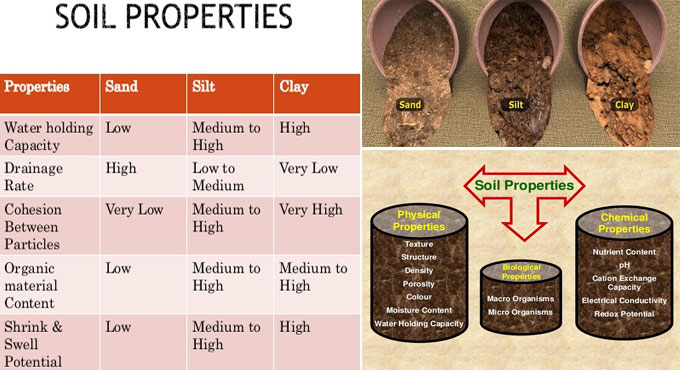
With compaction, the air is ejected from the existing voids in the soil. Compaction plays an important role in construction field since it make the engineering characteristics of soil better In the construction field to a great extent. In this exclusive civil engineering article, you will learn the impact of compaction on various characteristics of the soil.

It is found that the soil gets solid at the time of compaction. To make the compaction process smooth, some amount of water is included with the soil and the water content at which the highest dry density of soil can be sustained is defined as optimum moisture content.

Therefore, when the amount of water added remains under the optimum moisture content then it is defined as dry of optimum compaction. If the amount of water added remains in excess of the optimum moisture content then it is defined as wet of optimum compaction.

How does compaction influence the soil Properties? : The following properties of soil are affected with compaction -

1. Permeability
a. Compaction minimizes the existing voids in the soil and as a result permeability is also decreased.
b. At a specific density, for the similar soil sample, permeability becomes higher for soils which are compacted to dry of optimum as compared to those compacted to wet of optimum.


2. Compressibility
a. The Compressibility of compacted soil differs on the basis of the amount of pressure enforced.
b. For low-pressure range, compressibility is high for soils which are compacted to wet of optimum as compared to soil compacted to dry of optimum.
c. In the same way, for high-pressure ranges, compressibility is high for soils which are compacted to dry of optimum as compared to soil compacted to wet of optimum.


3. Shear Strength
a. Shear strength of soil compacted to dry of optimum remains in excess of those compacted to wet of optimum at lower strains.
b. At greater strain, soil compacted to wet of optimum will contain greater shear strength. o The shear strength of compacted soil is also impacted by the type of compaction, drainage conditions and type of soil.


4. Soil Structure
a. Soils compacted to dry of optimum have flocculated structure because of the attraction among soil particles caused by low water content.
b. Soils compacted to wet of optimum have scattered structure owing to the repulsive force among soil particles caused by high water content.


5. Swelling of Soil
a. When the soil is compacted to dry of optimum, the soil requires water and it swells quickly by getting in touch with water.
b. When water is compacted to wet of optimum, the soil particles are headed in a dispersed manner and no swelling happens.
c. To get rid of swelling, the compaction of soils should be made to wet of optimum.


6. Shrinkage of Soil
a. The scope of shrinkage is high for the soil compacted to wet of optimum than dry of optimum.
b. For dry of optimum compaction, soil particles are in random orientation and they remain in durable condition.
c. For wet of optimum, soil particles remain in parallel orientation and they become inconstant that streamlines the packing of particles producing shrinkage.


7. Pore Water Pressure
a. Pore water pressure is extreme for those soil whose water content is high. So, soils compacted to wet of optimum compaction will expose more pore water pressure as compared to soil compacted dry of optimum.


8. Stress-strain Behavior of Soil
a. Soils compacted to dry side of optimum will bear more stress for little strain and as a result, stress-strain curve of this type of soil is much sheerer and elastic modulus is high. Due to this, brittle failure may happen.
b. In the same way, soils compacted to wet of optimum will create more stress even for smaller stress. Therefore, Stress-Strain curve, in this case, is much flatter and plastic-type failure happens at a larger strain. These type of soils contain low elastic modulus.


Compaction Effects On Soil Structure

Read more
~~~~~~~~~~~~~~~~~~~~~~~~
Published By
Rajib Dey
www.constructioncost.co
~~~~~~~~~~~~~~~~~~~~~~~~

Tuesday, February 26, 2019

Brief overview of adjustable steel columns

Adjustable steel columns alias screw jacks or beam jacks, belong to hollow steel posts. The purpose of these columns is to provide strong support to the structure. A secured adjustable steel column threaded adjustment mechanism is employed to alter the height of the post with the help of a big screw.

They are frequently utilized in basements.

They are constructed as multi-part assembles, often known as telescopic steel columns, or as single-piece columns.

When a column is applied or set up improperly or its condition is damaged, the column becomes insecure. General faults occur due to persistent utilization of temporary columns, inappropriate installations and extreme exfoliating rust, all of which can cause abrupt collapsing of the column as well as the structure it supports. As a result injury and property damage will occur.

The following are possibly faulty conditions:

The diameter of the post remains under 3 inches as per 2006 International Residential Code (IRC), Section R407.3. Poles which remain under 3 inches go against the IRC, although they are not inevitably faulty. A 2½-inch post is sufficient to support the load over it, whereas a 4-inch post can buckle when the load goes beyond the structural strength of the post. Structural engineers normally take decision whether adjustable steel posts contain equivalent size.

Rust-inhibitive paint is not applied to safeguard the post. The IRC Section R407.2 defines:

All surfaces (interior and exterior) of steel columns should be provided with a shop coat of rust-inhibitive paint, exclusive of corrosion-resistant steel and steel treated with coatings to provide corrosion resistance.

Inspectors are unable to recognize paint as rust-inhibitive. In dry climates where rust is not happen, rust-inhibitive paint should not be applied. Visible signs of rust represent a possible deficiency.

The post is not straight. It should be checked that the highest lateral displacement among the top and bottom of the post should not go beyond 1 inch. However, endurable lateral displacement is influenced by several factors, like the height and diameter of the post. The post should not bend at its centre. Bending implies that the column is unable to endure the weight of the house.

The column is not mechanically attached with the floor. An inspector can’t identify whether a connection among the post and the floor subsists if this connection is wrapped with concrete.

The column is not attached with the beam. The post should be mechanically attached with the beam over to add extra resistance capacity against lateral displacement.

In excess of 3 inches of the screw thread are uncovered.

Cracks exist in upstairs walls. This condition may lead to the failure of the columns.

The following types of adjustable steel columns are commonly found - Single Piece Adjustable Columns, Telescoping Adjustable Columns

To learn how set up a adjustable steel column, go through the following link www.thespruce.com

Brief overview of adjustable steel columns

~~~~~~~~~~~~~~~~~~~~~~~~
Published By
Rajib Dey
www.constructioncost.co
~~~~~~~~~~~~~~~~~~~~~~~~

Monday, February 25, 2019

Some useful tips to restore active cracks in concrete

Active cracks in concrete stand for live cracks which are broaden in length, width, and depth in due course. Because of overloading & thermal enlargement, these cracks are developed e.g. cracks owing to freeze-thaw. There are different types of processes to restore active cracks which range from drilling and plugging, stitching, external pre-stressing and flexible sealing of cracks.

Because of unrestrained growth, there is chance for a new crack to be developed next to the restored active cracks. So, primarily, it is essential to settle reason of crack formation.

How to restore active cracks in concrete

The following processes are commonly used for restoring active cracks in concrete structures.

1. Drilling and Plugging through Crack: This process is suitable for the cracks which are found in straight lines. Under this process, a hole is drilled adjacent to the crack and stuffed with grout. This grout builds the key to lock the crack so that it can’t expand further. The grout avoids leakages and loss of soil. This method is inexpensive and less time is required for that.

Another useful process for plugging the drilled hole is stuffing it with epoxy mortar or any epoxy formulation with reinforcement bars which are arranged in the drilled hole. The bars applied contain predetermined length and size to fasten the cracks across.

The method includes drilling a hole of 50 to 75mm diameter based on the width of crack following the position of crack. The hole should be must be sufficiently big to bisect the crack along its full length and arrange adequate repair material to structurally bear the loads enforced on the key.

If water tightness is mainly required over structural load transmission, then the drilled hole is stuffed with a flexible material having low modulus. If both properties are necessary, the first hole is stuffed with grout and the second hole is stuffed with a flexible material.

2. Stitching of Cracks: Under this process, holes are drilled in such a manner that entry and exit points are provided across the cracks. Through the holes, several U-shaped metallic staples are provided through the holes and the holes are secured firmly at the end with grout or epoxy.

3. External Prestressing: Post-tensioning method is used to close flexural cracks in reinforced concrete. It will stop the cracks to be expanded further or fixed entirely. The process offers compression force so as to correct the tendons and then supplementary residual compressive force.

This process needs anchorage of the tie-rods to the anchoring device tied to the beam.

4. Flexible Sealing: Under flexible sealing method, bond breaker is utilized for repairing active cracks.

Prior to apply a repair method for active cracks, it should be checked that whether it is essential to make the flexural or tensile strength better across the crack. To sustain the strength, it is required to set up an expansion joint close to the repaired crack so that further cracking can’t happen adjacent to the corrected one in due course of time.

Some useful tips to restore active cracks in concrete

Read more
~~~~~~~~~~~~~~~~~~~~~~~~
Published By
Rajib Dey
www.constructioncost.co
~~~~~~~~~~~~~~~~~~~~~~~~

Friday, February 22, 2019

LIMIT STATE DESIGN: (A Text-book of Reinforced Concrete Structures)

Dr. Ram Chandra, M.E. (Hons.), B.E., M.I.E., Ph.D (Roorkee), Professor of Structural Engineering has written an exclusive e-book alias LIMIT STATE DESIGN: (A Text-book of Reinforced Concrete Structures).

In this book, the author briefly explains each basic concept, elementary method, equation or theory of interest to the student of reinforced concrete design in simple manner. S.I. system of units and new code IS: 456-1978 are fully utilized in the text.

The book is specifically designed for degree, diploma and A.M.I.E. students in different branches of engineering. This book on ‘Limit State Design’ is based on the provisions of code IS: 456-1978. Both the topics of this subject, ‘Limit State of Collapse’ and ‘Limit State of Serviceability’ are clearly explained to design the reinforced concrete structures and the structural elements.

Given below, some exclusive features of the book :-

a. Each topic presented is described in detail.
b. This book is entirely composed of SI system of units and with adherence to the Indian Standard specifications (IS: 456-1978) all through the text.
c. The text of this subject is started, presented and explained in such a manner that is suitable for the students.
d. The different notations applied all through throughout this text book adhere to code of practice IS: 456-1978.

e. A number of design examples are provided in each chapter to demonstrate the theory and practice. Unsolved design problems are also provided in each chapter.
f. The diagrams clearly demonstrate the detailing of reinforcement.
g. This book abides by the current design practice.


To access the book online, click on the following link. www.amazon.in

LIMIT STATE DESIGN: (A Text-book of Reinforced Concrete Structures)

~~~~~~~~~~~~~~~~~~~~~~~~
Published By
Rajib Dey
www.constructioncost.co
~~~~~~~~~~~~~~~~~~~~~~~~


Thursday, February 21, 2019

Some useful guidelines to work out the total loads on a column & footing

This article is about calculation of loads for column and footings design.
The following types of loads operate on a column :-
1. Self weight of the column x Number of floors
2. Self weight of beams per running meter
3. Load of walls per running meter
4. Total Load of slab (Dead load + Live load + Self weight)
The columns are also susceptible to bending moments which should be included in creating the final design. There are different types of advanced structural design software like ETABS or STAAD Pro which can be applied to design a good structure efficiently. The calculation for structural loading In professional practice is based on some fundamental assumptions.
For Columns: Self weight of Concrete is approximately 2400 kg per cubic meter that is identical to 240 kN. Self weight of Steel is approximately 8000 kg per cubic meter. Suppose a large column having size of 230 mm x 600 mm with 1% steel and 3 meters standard height, the self weight of column is approximately 1000 kg per floor, that is identical to 10 kN. So, here, the self weight of column is taken as among 10 to 15 kN per floor.
For Beams: The calculation is same as above. Suppose, each meter of beam contains dimensions of 230 mm x 450 mm exclusive of slab thickness. So, the self weight is approximately 2.5 kN per running meter.
For Walls: Density of bricks differs among 1500 to 2000 kg per cubic meter. For a 6″ thick wall with 3 meter height and 1 meter length, the load can be measured per running meter equivalent to 0.150 x 1 x 3 x 2000 = 900 kg which is equivalent to 9 kN/meter. The load per running meter can be measured for any brick type by following this method.
For autoclaved, aerated concrete blocks like Aerocon or Siporex, the weight per cubic meter should remain among 550 to 700 kg per cubic meter. If these blocks are utilized for construction, the wall loads per running meter remains as low as 4 kN/meter, that leads to cutback in construction cost.
For Slab: Suppose the thickness of the slab is 125 mm. Now, each square meter of slab contains a self weight of 0.125 x 1 x 2400 = 300 kg that is similar to 3 kN. Suppose, the finishing load is 1 kN per meter and superimposed live load is 2 kN per meter. So, the slab load should remain 6 to 7 kN per square meter.
Factor of Safety: Finally, once the calculation of the entire load on a column is completed, the factor of safety should also be taken into consideration. For IS 456:2000, the factor of safety is 1.5.
Some useful guidelines to work out the total loads on a column & footing

~~~~~~~~~~~~~~~~~~~~~~~~~~
Published By
Rajib Dey
www.constructioncost.co
~~~~~~~~~~~~~~~~~~~~~~~~~~

Wednesday, February 20, 2019

Some useful tips to enhance the longevity of concrete piles

If concrete is mixed perfectly and compacted to a solid impervious, the longevity of all the construction materials is significantly increased in a non aggressive atmosphere.

The strength of concrete is influenced by sulphate and sulfuric acid that takes place normally in soils, erosive chemicals existent in industrial waste in fill materials and organic acids and carbon dioxide existent in ground water.

A solid, properly compacted concrete can efficiently safeguard the concrete piles, pile cap and ground beams against the attack by sulphates. The low penetrability of dense concrete resists or significantly controls the ingress of the sulphates into the pore spaces of the concrete.

That's why high strength precast concrete piles are mostly recommended for application. Although these are not acceptable for all the site conditions and bored cast in situ / driven cast in situ piles, so, at the time of application, these should be designed perfectly to attain necessary degree of impenetrability and defiance to aggressive action.

Both high alumina cement and super sulphated cement are not suitable for piling work. As an alternative, reliance is provided on the resistance of solid impervious concrete that is formed with a low water cement ratio. Coating of tar or bitumen on the surface, metal sheeting or glass fibre wrapping filled with bitumen may be chosen.

A layer of heavy gauge polythene sheeting provided on a sand carpet or on blinding concrete is arranged to safeguard pile caps and ground beams on the underside. The vertical sides are safeguarded once the formwork is eliminated with the use of hot bitumen spray coats, bituminous paint, trowelled on mastic asphalt or adhesive plastic sheeting.

Preventative measures against the aggressive action caused by sea water on concrete should only be taken into consideration with regard to precast concrete piles. Cast in situ concrete is utilized only as a centering to steel tubes or cylindrical precast concrete shell pills. The precast concrete piles for marine condition, a minimum ordinary portland cement content of 360 kg/m3 and a maximum water cement ratio of 0.45 by weight should be chosen.

Some useful tips to enhance the longevity of concrete piles

Read more
~~~~~~~~~~~~~~~~~~~~~~~~
Published By
Rajib Dey
www.constructioncost.co
~~~~~~~~~~~~~~~~~~~~~~~~

Tuesday, February 19, 2019

How to measure superimposed loads on a column

The objective of a column is to withstand axial and lateral forces and transmit them securely to the footings in the ground.

In this exclusive article, you will learn how to work out the superimposed loads on a column in a structure with some easy-to-follow steps.

Columns provide support to the floors in a structure. Slabs and beams transmit the stresses to the columns. So, it is crucial to make a strong column.

A column stands for a compression member, the effective length of which surpasses three times the minimum lateral dimension. Compression members whose lengths remain under three times the minimum lateral dimension, are constructed with plain concrete.

The axial load bearing strength of a column is derived from the follwoing formula :-

Reinforced Concrete Columns

Besides, axial loads, the column design is dependent on several other factors. Because of beam spans, wind loads, seismic loads, point loads and various other factors, the bending moments and tortional forces are produced.

A column is categorized on the basis of various factors :-

1. Depending on shape
• Rectangle
• Square
• Circular
• Polygon


2. Depending on slenderness ratio: The ratio of the effective length of a column to the minimum radius of gyration of its cross section is known as the slenderness ratio.

• Short RCC column, =< 10
• Long RCC column, > 10
• Short Steel column, =<50
• Intermediate Steel column >50 & <200
• Long Steel column >200


3. Depending on the type of loading
• Axially loaded column
• A column subjected to axial load and unaxial bending
• A column subjected to axial load and biaxial bending


4. Depending on pattern of lateral reinforcement
• Tied RCC columns
• Spiral RCC columns


Least eccentricity
Emin > l/500 + D/30 >20
Where, l denotes unsupported length of column in ‘mm’
D = lateral dimensions of column


The following types of Reinforcements for columns are found :-

Longitudinal Reinforcement
• Least area of cross-section of longitudinal bars should be minimum 0.8% of gross section area of the column.
• Maximum area of cross-section of longitudinal bars should not be in excess of 6% of the gross cross-section area of the column.
• The bars should not be below 12mm in diameter.
• Least number of longitudinal bars should be 4 in rectangular column and 6 in circular column.
• Distance of longitudinal bars measured along the perimeter of a column should not go above 300mm.


Transverse reinforcement
• It may appear in the form of lateral ties or spirals.
• The diameter of the lateral ties should not remain below 1/4th of the diameter of the greatest longitudinal bar and in no case below 6mm.


The pitch of lateral ties should not go beyond
• Minimum lateral dimension
• 16 x diameter of longitudinal bars (small) • 300mm


Helical Reinforcement
The diameter of helical bars should not remain below 1/4th the diameter of largest longitudinal and not below 6mm.
The pitch should not go above (if helical reinforcement is permitted);
• 75mm
• 1/6th of the core diameter of the column


Pitch should not remain under,
• 25mm
• 3 x diameter of helical bar
Pitch should not surpass (if helical reinforcement is not permitted)


Least lateral dimension
• 16 x diameter of longitudinal bar (smaller)
• 300mm


Reinforced Concrete Columns

Read more
~~~~~~~~~~~~~~~~~~~~~~~~
Published By
Rajib Dey
www.constructioncost.co
~~~~~~~~~~~~~~~~~~~~~~~~

Monday, February 18, 2019

Different components of super structure

Superstructure stands for segments of the structure that is situated over the surface of the ground. The superstructure is built with different sections of walls, roof, doors, and windows, flooring. The sections of the structure situated on the grounds and underneath the ground floor level are known as the plinth.

The objective of superstructure is to bear different types of loads operating on the structure which range from dead load, live, load, wind load etc. These loads are then transferred to the underlying soil through the substructure.

Each element of superstructure is applied as a specific purpose, but the prime function is to arrange privacy, safety to the inhabitants. Wall and roof safeguards from the surrounding, doors permit entry and give safety, windows arrange requisite sunlight and fresh air and floor provides a leveled surface to live and protection from beneath.

Building superstructure

Column: A column in structural engineering stands for a vertical structural component that disperses the weight of the structure over to other structural components underneath , through compression.

Floor: A floor normally comprises of a support structure known as a sub-floor on top on which a floor cover is placed to arrange a walking surface.

Roof wall :

Flat – Should contain a slight slope for drainage

Shed – A single slope

Gable – Two slopes intersect at a ridge. Two walls expand up to the ridge.

Hip – Two gables, a pyramid is treated as a hip roof.

Gambrel – Four slopes in one direction, the usual barn roof.

Mansard – A four-sided gambrel-style hip roof formed with two slopes on each of its sides with the lower slope, perforated by dormer windows, at a steeper angle than the upper.

Beam: Beam stands for an inflexible structural member formed to bear and transmit transverse loads across space to supporting components.

Different components of super structure

~~~~~~~~~~~~~~~~~~~~~~~~
Published By
Rajib Dey
www.constructioncost.co
~~~~~~~~~~~~~~~~~~~~~~~~

Saturday, February 16, 2019

Common structural members in a building

In this civil engineering article, you will get detail information on different types of structural members in a building.

Beam: Beam stands for a flexure member of the structure. It is exposed to transverse loading like vertical loads, and gravity loads. With these loads, shear and bending are formed inside the beam. Beams belong to horizontal structural members to bear a load successfully.

Beam is generally applied for withstanding vertical loads, shear forces and bending moments.

Columns: A long vertical member that mostly undergoes compressive loads & buckling loads is known as column. Columns stand for vertical, structural members of a structure. They transmit load from beams to footings. Columns are mostly utilized to support beams or arches on which the upper sections of walls or ceilings rest.

Strut: Strut is a compressive member of a structure. This structural member is driven from opposite ends. The purpose of a strut is to withstand compression.

Ties: A tie stands for a structural member that is extended from opposite ends. A tie mainly deals with tension.

Beam-Column: A structural member that is exposed to compression and flexure is known as beam column.

Grid: A group of beams which overlap each other at right angles and exposed to vertical loads is known as grid.

Cables and Arches: Cables are normally suspended at their ends and are granted to sag. The forces then turn to pure tension and are headed along the axis of the cable. Arches have the similarity with cables apart from they are inverted. They bear compressive loads which are directed along the axis of the arch.

Plates and Slabs: Plates belong to three dimensional flat structural components generally constructed with metal which are frequently utilized in floors and roofs of structures. Slabs are identical to plates apart from that they are normally constructed with concrete.

Common structural members in a building

Read Continue
~~~~~~~~~~~~~~~~~~~~~~~~
Published By
Rajib Dey
www.constructioncost.co
~~~~~~~~~~~~~~~~~~~~~~~~

Friday, February 15, 2019

POLEFDN – A excel based construction program for pole foundation analysis

POLEFDN is a MS-excel based spreadsheet program that can be used for making analysis of a pole foundation on the assumption of the application of a inflexible round pier that is supposed free (unrestrained) at the top and exposed to lateral and vertical loads. The spreadsheet particularly makes calculation for the necessary embedment depth, the maximum moment and shear, the plain concrete stresses, and the soil bearing pressures.

This program stands for a workbook that comprises of the following six (6) worksheets:

• Doc - Documentation sheet
• Pole Fdn (Czerniak) - Pole foundation analysis for free-top round piers with PCA/Czerniak method
• Pole Fdn (UBC-IBC) - Pole foundation analysis for free-top round piers with UBC/IBC method
• Pole Fdn (OAAA) - Pole foundation analysis for free-top round piers with OAAA method

• Granular Soil (Teng) - Pole foundation analysis in granular soil with USS/Teng method
• Cohesive Soil (Teng) - Pole foundation analysis in cohesive soil with USS/Teng method


Given below, some useful features of the program :-

This program can deal with both horizontally and vertically applied loads. The vertical load may contain an associated eccentricity that leads to an additional overturning moment to be always assumed to add directly to the overturning moment formed with the horizontal load.

This program guesses that the top of the pier remains at or over the top of the ground surface level.

This program guesses that the actual resisting surface remains at or under the ground surface level. It takes into account any weak soil or any soil that is detached at the top.

The "Pole Fdn(Czerniak)" worksheet guesses that the inflexible pier rotates about a point situated at a distance, 'a', under resisting the surface. The highest shear in pier is supposed to be at that 'a' distance, whereas the maximum moment in the pier is supposed to be at a distance = 'a/2'.

The "Pole Fdn(Czerniak)" worksheet works out the "plain" (unreinforced) concrete stresses, compression, tension, and shear in the pier. The corresponding permissible stresses are also set on the basis of the strength (f'c) of the concrete. It is performed to check whether the steel reinforcing is actually necessary or not. The permissible tension stress in "plain" concrete is supposed to be equivalent to 10% of the value of the permissible compressive stress.

The "Pole Fdn(Czerniak)" worksheet measures the actual soil bearing pressures along the side of the pier at equivalent distances to 'a/2' and 'L'. The relevant permissible passive pressures at those locations are set for comparison.

As all overturning loads are protected with the passive pressure against the embedment of the pier, this program guesses that the pier functions in direct end bearing to withstand only the vertical loading. The bottom of pier bearing pressure is measured that contains the self-weight of the pier, assumed at 0.150 kcf for the concrete.

To download the program, click on the following link www.cesdb.com

POLEFDN – A excel based construction program for pole foundation analysis

~~~~~~~~~~~~~~~~~~~~~~~~
Published By
Rajib Dey
www.constructioncost.co
~~~~~~~~~~~~~~~~~~~~~~~~

Thursday, February 14, 2019

Plaster of Paris In Construction – Uses and Benefits

Plaster of Paris (POP) is a elementary building material that is mainly applied for coating walls and ceilings as well as for making architectural designs. It comes as dry powder and gets solidified when used along with water and heat.

The following types of plaster of paris is mainly available :-

a. Plaster of paris (Gypsum)
b. Lime Plaster
c. Cement Plaster


POP is originated by incomplete calcination of gypsum or calcium sulfate at 100 – 190 degree C without any admixture. The setting time is 5 – 20 min.

Benefits of Plaster of Paris:

1. It is light in weight and long lasting.
2. It contains low thermal conductivity.
3. It has strong resistance capacity against fire and it is considered as a very good heat insulating material.

4. It does not shrink at the time of setting and as a result it does not form cracks at the time of heating or setting.
5. It develops a thick surface to withstand normal knocks once drying is completed.
6. It blends easily with water and disperses quickly and level.
7. It contains good adhesion on fibrous materials.
8. It provides a solid surface on which the colours are set.

9. It does not provide any chemical action on paint and does not produce alkali attack.
10. Plaster of Paris provides a elegant interior finish. Due to inclusion of gypsum in POP, there is lot of shine and smoothness.
11. It can be easily changed into any shape.


Drawbacks of Plaster of Paris:

1. Gypsum plaster is not recommended for exterior finish as it is dissolved in water to some extent.
2. It’s cost is high as compared to cement or cement lime plaster.
3. It cannot be applied in moist situations.
4. Skilled labor should be appointed for proper application and consequently huge labour cost is required for using plaster of Paris.


Plaster of Paris In Construction – Uses and Benefits

Read Continue
~~~~~~~~~~~~~~~~~~~~~~~~
Published By
Rajib Dey
www.constructioncost.co
~~~~~~~~~~~~~~~~~~~~~~~~

Wednesday, February 13, 2019

Principles of chain surveying

Chain survey belongs to the easiest method of surveying. Under this type of survey, only measurements are captured in the construction site, and the other works, like plotting measurement etc. are carried out in the office. Irrespective of angular measurements, only linear measurements are undertaken. It is mostly effective for small plane areas having very few details. If it is performed efficiently, it provides quite perfect results.

To conduct this survey, the following items are required in job site - Chain, Tape, Ranging-Rod, Arrows, Cross staff

Relevance of Chain Survey - Chain survey can be undertaken for the following purposes:

1. The area required to conduct survey is relatively small
2. The ground is level to some extent
3. The area is open and
4. Details to be gathered are simple and less.


Survey Station - Survey stations are categorized as follow : Main Stations, Subsidiary or tie

Main Stations: Main stations refer to the end of the lines, which manage the boundaries of the survey, and the lines which attach the main stations remind of the main survey line or the chain lines.

Subsidiary or the tie stations: Subsidiary or the tie stations belong to the points chosen on the main survey lines, where it is important to trace the interior detail like fences, hedges, building etc.

Tie or subsidiary lines: A tie line connects two fixed points on the main survey lines. It facilitates to verify the exactness of surveying as well as trace the interior details. The location of each tie line should be adjacent to some features, like paths, building etc.

Base Lines: It is the primary and longest line, which moves roughly through the center of the field. All the other measurements to demonstrate the details of the work are obtained relating to this line.

Check Line: A check-line also called as proof-line belongs to a line that attaches the apex of a triangle to some fixed points on any two sides of a triangle. A check-line is calculated to verify the exactness of the framework. The length of a checking line, as calculated on the ground should satisfy its length on the plan.

Offsets: Offsets stand for the lateral measurements from the baseline to secure the positions of the several objects of the work in relation to the baseline. These are normally set at right angle offsets. It is also drawn by applying a tape.

Chain survey method:
1. Reconnaissance: The initial examination of the area prepared for survey is known as reconnaissance. The surveyor examines the area to be surveyed as well as arranges index sketch or key plan.
2. Marking Station: Surveyor settles the required no of stations at areas from where maximum possible stations can be arranged.


The marking is done with the following processes:

a. Setting ranging poles
b. Pushing pegs
c. Marking a cross if the ground is solid
d. Digging and setting a stone.


3. After that, the surveyor chooses the way for transforming the main line, that should be horizontal and dirt free as possible and should move around through the center of work.
4. Then ranging roads are secured on the stations.
5. As soon as the stations are fixed, chaining should be done.
6. Create ranging wherever required.
7. Work out the change and offset.
8. Enter in the field the book.


Principles of chain surveying

Read Continue
~~~~~~~~~~~~~~~~~~~~~~~~
Published By
Rajib Dey
www.constructioncost.co
~~~~~~~~~~~~~~~~~~~~~~~~

Tuesday, February 12, 2019

Some outstanding ideas to design your home with Concrete

Besides, concrete, other materials like steel, fibre, plastic, glass, wood and other superior materials can also be used together with concrete to build up homes. Now-a-days, concrete is extensively utilized for the construction of commercial, residential, institutional, and industrial buildings due to it’s adaptability, cost-effectiveness and the easy accessibility of raw materials for production.

In recent times, concrete home construction is gaining popularity because of the factors like sustainability, green building, disaster resistance, energy conservation, and safety. To satisfy these requirements efficiently, the engineers offer some unique design ideas.

Concrete Home Design Ideas: Designers have provided different types of design ideas for the construction of concrete homes owing to its versatility and easy accessibility of construction materials. Motivations that put into effect or head over to new design ideas are dissimilar, as for example, some design ideas get inspiration from nature while some from energy efficiency, aesthetics, sustainability, and recycling materials.

Advantages of Concrete Homes:

1. Stable
One of the most outstanding properties of concrete is its strength which offers comfortable shelter from inclement weather, and minimizes property damage while safeguarding from severe weather and natural disasters.


2. Long-lasting
Future maintenance is not required for home as a result the construction cost is reduced significantly.


3. Adaptable
Concrete is a multifaceted material from which any shape and form can be developed. This features facilitates the designers to produce innovative designs on the basis of the demand of client and situations under considerations.


4. Eco-Friendly
The materials necessary to develop concrete are accessible in local areas. Recycled materials like recycled aggregate, pozzolanic cementitious materials like fly ash and silica fumes are utilized to build up concrete.


It results in decreasing CO2 emission throughout cement production since a smaller quantity of cement is required for production.

5. Advantages throughout life-cycle of the Structure
Concrete homes offer various advantages and benefits all through their life span. As for example, chills inside area of the house and consequently curtail energy consumption, and give protection against disasters like fire; hurricane; earthquake; and flood.


Besides, concrete contains low volatile organic compound and it does not impact indoor air quality. Finally, it can be recycled to develop recycled concrete aggregate.

To get some of the most outstanding and award-winning design ideas for construction of concrete homes, click on the following link theconstructor.org

Some outstanding ideas to design your home with Concrete

~~~~~~~~~~~~~~~~~~~~~~~~~~
Published By
Rajib Dey
www.constructioncost.co
~~~~~~~~~~~~~~~~~~~~~~~~~~