adsense analytic

Showing posts with label Design Construction. Show all posts

Thursday, February 14, 2019

Plaster of Paris In Construction – Uses and Benefits

Plaster of Paris (POP) is a elementary building material that is mainly applied for coating walls and ceilings as well as for making architectural designs. It comes as dry powder and gets solidified when used along with water and heat.

The following types of plaster of paris is mainly available :-

a. Plaster of paris (Gypsum)
b. Lime Plaster
c. Cement Plaster


POP is originated by incomplete calcination of gypsum or calcium sulfate at 100 – 190 degree C without any admixture. The setting time is 5 – 20 min.

Benefits of Plaster of Paris:

1. It is light in weight and long lasting.
2. It contains low thermal conductivity.
3. It has strong resistance capacity against fire and it is considered as a very good heat insulating material.

4. It does not shrink at the time of setting and as a result it does not form cracks at the time of heating or setting.
5. It develops a thick surface to withstand normal knocks once drying is completed.
6. It blends easily with water and disperses quickly and level.
7. It contains good adhesion on fibrous materials.
8. It provides a solid surface on which the colours are set.

9. It does not provide any chemical action on paint and does not produce alkali attack.
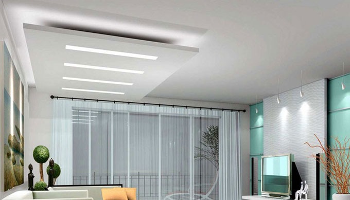
10. Plaster of Paris provides a elegant interior finish. Due to inclusion of gypsum in POP, there is lot of shine and smoothness.
11. It can be easily changed into any shape.


Drawbacks of Plaster of Paris:

1. Gypsum plaster is not recommended for exterior finish as it is dissolved in water to some extent.
2. It’s cost is high as compared to cement or cement lime plaster.
3. It cannot be applied in moist situations.
4. Skilled labor should be appointed for proper application and consequently huge labour cost is required for using plaster of Paris.


Plaster of Paris In Construction รข€“ Uses and Benefits

Read Continue
~~~~~~~~~~~~~~~~~~~~~~~~
Published By
Rajib Dey
www.constructioncost.co
~~~~~~~~~~~~~~~~~~~~~~~~

Thursday, February 7, 2019

Details about various sections of bridge

All the major elements are arranged within three main bridge areas – Foundation (that retains the shallow or deep base of the bridge and transmits it’s load to the bearing strata, it comprises of foundations underneath the primary span of the bridge and the abutments underneath starting points of the bridge), Substructure (piers, abutments, spandrels, caps, bearings, and other elements that retains the top part of construction) and Superstructure (all the segments of the bridge which are assembled on top of the supporting substructure system, it comprises of various components like decking, girders, slab, and everything arranged over the main deck like posts, steel truss system, bridge girder, cable-stayed system, cable suspended systems and more).

The followings are the major elements of the modern bridges:

Abutment – Endpoints of the bridge. They are reinforced to facilitate withstanding extreme lateral pressures.

Pile (also called as beam, footing, and pier) – It stands for reinforced concrete post that is pushed into the ground to function as the leg or support for the bridge. The extent among piles is worked out to provide support to the rest of the structure that will be placed on top of them.

Cap – Cap is located on top of the pile beam that gives extra support and distributes the load to the piles underneath. The amalgamation of Pile and Cap elements is known as Bent.

Girder or Span – It is one of the major components of the bridge that attaches all the Piles beams. It involves several simple spans, a single continuous span that is supported with numerous beams, cantilever spans and cantilever spans with the suspended span among them. They are normally formed with metal or reinforced concrete as well as in the form of haunches girded be bear more load. Girder sections are usually not formed with a simple block of material but built up with truss network (or Orthotropic beams) that enhance their resistance capacity against load. Girders are also utilized as a part of rigid frame network where they are totally attached with frame legs (that may appear as inclined or in V shape).

Superstructure truss network – Truss network that provides supports to travel surface is built with three basic ways – Deck truss where traffic passes on top of truss network, Pony truss where truss network passes among two parallel walls of trusses, and via truss that includes extra cross-braced truss network over and below the traffic.

Deck beam – Simple continuous decks are created with metal or reinforced concrete. They comprise of sub-components like approach slab (attaches main bridge decking with the ground on both sides of the bridge), expansion joint, drainage scupper, curb, running surface, footpath.

Barriers – These are the sides of the bridge decks normally contain extra barrier components like railings, handrails and ground fixtures.

Arch – Arches on the bridges are differentiated with the number of hinges they contain (normally among zero or three) which ascertain the volume of stress and load they can bear securely, and the type of material they are built up (solid material, truss system). Arches underneath the bridge are known as spandrel-braced (cantilever) or Trussed deck arch.

Spandrel – Spandrels belong to the almost triangular space among the main pillar of the bridge and decking. Stone bridges employ filled “closed” spandrels deck arches, whereas the modern bridges are constructed with metal having open spandrel deck arch configurations.

Truss – Framework is created by attaching triangles and other forms that disperse load and stress forces across its whole structure. They are generally segregated into various categories like simple truss (King and Queen posts), covered bridge truss (multiple kingpost truss, Howe truss, long truss, Burr arch truss, town lattice truss, Haupt, Smith, Partridge and Child truss), Pratt truss (and it’s many variations), Whipple truss, Warren truss variations, Howe truss, Lenticular truss, Fink truss, multiple Cantilever truss variations, and suspension truss arches.

Details about various sections of bridge

Read more
~~~~~~~~~~~~~~~~~~~~~~~~~~
Published By
Rajib Dey
www.constructioncost.co
~~~~~~~~~~~~~~~~~~~~~~~~~~

Tuesday, January 29, 2019

The details about bills of quantities

With the measurement of quantities, the total price can be evaluated more elaborately & precisely to give cost feedback on the job, that at the same time can be applied numerically in cost planning of other works.

Bills of quantities offer the best possible ways to manage the cost of variations in the contract. It is extensively utilized for various post-tender work like material scheduling; construction planning; cost analysis; and cost planning.

The method of working out the quantities prior to tender is a crucial test regarding what is drawn and stated can in fact be built. By examining the drawings and reviewing the construction in detail is definitely helpful in recognizing the issues which may be omitted initially.

The direct costs & indirect costs should be taken into consideration for determining the entire cost of the project which are included in various segments of the BOQ.

As the cost is identified prior to commencement of the construction, a superior level of price certainty is maintained for the construction project.

Facilitates to provide a low tender price.
Accommodates with design changes and assists the cost management process.
Provides superior quality of tender document.


Minimize the risk of contractors managing the information in the BQ for their own purposes.
Bypass the risks with regard to both time and cost since the projects are calculated on the basis of the overall floor area.
The valuation of progress payment becomes simple with detail information as given in BQ.


May pass up the tendency of contractor to build up a conspire group and bid high for projects.

Video Source: Civil Engineer

~~~~~~~~~~~~~~~~~~~~~~~~~
Published By
Rajib Dey
www.constructioncost.co
~~~~~~~~~~~~~~~~~~~~~~~~~

Monday, January 28, 2019

Types of formworks found in construction

Generally, steel or concrete is used in formwork to build part of the permanent structure. Temporary formwork can be struck and recycled from any inexpensive and easily worked material, timber, steel and GRC/GRP.

The formwork that should be utilized under the water, should abide by the following conditions :

a. Support the concrete in its designed profile during the plastic phase
b. Properly affixed into position.
c. Cover the concrete from scour, washout and abrasion till unless it gets solidified.
d. Endure mistakes in development level or alignment of adjoining work
e. Ability to resist the static and dynamic loading caused by concrete, tides, waves and currents.


It is designed in the context of the permanent works and be abandoned in situ or as temporary works either to be abandoned in situ or smitten and recycled.

The following types of formworks are mostly found :-

Ceiling Formwork: Ceiling formwork belongs to the type of formwork commonly found in structures/buildings.

The formwork sheeting comprises of sheeting boards or prefabricated sheeting panels. The formwork sheeting is located on squared timber formwork bearers to be provided on main bearers capturing the forces to round timber columns. With smaller rooms, the main bearer along with two columns develops a trestle. Diagonal board bracings are arranged to manage horizontally acting forces. The round timber columns are arranged on double wedges which function as stripping aid and correction device.

Beam Formwork: Beam formwork contains prefabricated formwork sheeting parts (sheeting bottom and side sheeting panels). Such individual parts are erected on the basis of the beam dimensions stated in the project. For prefabrication of the formwork sheeting parts, a special preparation table should be created on site.

Column Formwork: Same as beam formworks, the sheeting of column formworks is prefabricated based on the column dimensions from sheeting boards attached with cover straps.

The sheeting panels are arranged in a foot rim which is secured in the soil with steel bolts.

The foot rim consists of double-nailed boards. The foot rim must be exactly measured-in because it is decisive for the exact location of the column. It has the same functions as the thrust-board for foundation or beam formwork.

When the sheeting panels are implanted in the foot rim, vertical arch timbers are arranged to undertake the forces from the cover straps of the formwork sheeting.

Around the arch timbers, that contains the function of walers, column clamps of flat steel are braced with wedges or a rim of boards is provided same as the foot rim. Supplementary formwork tying with tie wires or steel screws is not required.

The distances of the clamps are mentioned in the formwork project. Generally, they are roughly 700 mm.

The column in the formwork is laterally fastened by diagonal board braces.

Types of formworks found in construction

Read more
~~~~~~~~~~~~~~~~~~~~~~~~~
Published By
Rajib Dey
www.constructioncost.co
~~~~~~~~~~~~~~~~~~~~~~~~~

Tuesday, January 22, 2019

Difference Between Flexible Pavement and Rigid Pavement

The pavement designing is complicated task in Transportation Engineering. The most recognized methods for pavement design are Rigid pavement and Flexible pavement. The pavement surface has good longevity and it can resist the load operating from the wheel tyres.

Given below, the functional requirement of highway pavements :-

1. Flexible pavement and Rigid pavement contain superior riding quality
2. It should be less slippery
3. It should be rigid
4. It should contain adequate friction keeping the power of the vehicle unchanged.


Variation among Rigid Pavement and Flexible Pavement

1. Flexible Pavement

a. Load is transmitted from grain to grain to the lower layers
b. The design is totally based on the subgrade strength.
c. IRC 37-2012 code is applied for making the design of flexible pavement
d. The strength of flexible pavement is influenced by the aggregate interlock, particle friction and cohesion.
e. Flexible pavement demonstrates the deflection of subgrade at the surface of the pavement.
f. Design life lasts for 15 years.


Rigid Pavement:

1. Rigid pavement contains a strong flexural strength that is considered as the vital factor of design.
2. Rigid pavement contains a concrete layer at the top, the base course and soil subgrade remain underneath.
3. Rigid pavement disperses the load over a broad area due to its high flexural strength.
4. Load is transmitted through slab action.
5. The total thickness of the pavement remains under flexible pavement.

6. IRC: 58-2011 is utilized for making the designing of Rigid pavement.
7. Design life extends for 30 years


Difference Between Flexible Pavement and Rigid Pavement

Read more
~~~~~~~~~~~~~~~~~~~~~~~~~
Published By
Rajib Dey
www.constructioncost.co
~~~~~~~~~~~~~~~~~~~~~~~~~

Saturday, January 19, 2019

Advantages of microsillica in concrete

Microsilica alias silica fume or condensed silica fume stands for is a mineral admixture that is formed with very fine solid glassy spheres of silicon dioxide. Most microsilica particles remain under 1 micron (0.00004 inch) in diameter, normally 50 to 100 times finer as compared to average cement or fly ash particles. Microsilica belongs to a by-product of the industrial manufacture of ferrosilicon and metallic silicon in high-temperature electric arc furnaces.

Microsilica may be suitable in managing heat formation in mass concrete. It can also be combined with fly ash to provide superior result.

If pozzolanic materials are integrated with concrete, the existent silica in these materials makes a reaction with the calcium hydroxide produced throughout the hydration of cement and develops supplementary calcium silicate hydrate (C – S – H) that enhances the strength and the mechanical properties of concrete.

Types of Microsilica: Microsilica is categorized as follow -

1. Powdered microsilica, 2. Condensed microsilica, 3. Slurry microsilica

Impacts of Microsilica on Concrete

1. Fresh Concrete

a. It decreases the scope of segregation, so it is applied as pumping aid.
b. It almost reduces bleeding, as a result finishing work commences before time.
c. Workability and uniformity of concrete reduces.


2. Hardened Concrete: The inclusion of microsilica enhances the following characteristics of hardened concrete -

a. Improves compressive strength that leads to improve flexural and tensile strength.
b. Bond strength
c. Abrasion resistance
d. Lessens permeability; consequently, it safeguards reinforcement steel against corrosion.
e. Impact and cavitations resistance.
f. Sulphate Resistance
g. Heat Reduction
h. Chemical Resistance


Properties of Microsilica:

1. Microsilica belongs to a grey; almost white to black powder.
2. Spherical particles remain under 1mm in diameter.
3. The mass density of microsilica is dependent on the degree of densification and differs from 130 to 600 kg/m3.
4. The specific gravity of microsilica differs among 2.2 to 2.3


Benefits:

a. Minimizes thermal cracking resulting from the heat of cement hydration.
b. Enhance the strength to resist against sulphate and acidic waters.
c. Minimizes the growth of temperature in preliminary stage.
d. Silica fume is cheap; therefore, it is inexpensive.
e. It minimizes the entire slab weight and cost.
f. Inclusion of microsilica reduces efflorescence caused by the refined pore structure and increased consumption of the calcium hydroxide.


Advantages of microsillica in concrete

Read more

~~~~~~~~~~~~~~~~~~~~~~~~~
Published By
Rajib Dey
www.constructioncost.co
~~~~~~~~~~~~~~~~~~~~~~~~~

Thursday, January 17, 2019

Design of Beam

1. Estimation of constants. -For the specified set of stresses, determine KC, JC and RC.
2. Kc= M~cbc/M~cbc+~st
3. Jc= 1-(Kc/3)
4. Rc= 0.5*L*Kc Jc
5. Estimation of bending moment. Suppose appropriate values of overall depth and breadth of beam, and find out the effective span. Work out the self-weight and total U.D.L. and maximum bending moment in the beam.
6. Design of the section. Workout the effective depth of the beam with the following expression:
7. d= [(M)/ (RC*b)] 0.5
8. Reinforcement. Workout the area with the formula.
9. Shear Reinforcement. Workout the maximum shear force in the beam.
10. Verify for Development length at the end.
11. Ld<= (M1/V) +L0.
Design of column:
1. Find out the allowable stresses in concrete, longitudinal bars and ties.
2. Determine the super impose load that should be borne by the column.
3. Find out the area from the following expression - P= ~cc *Ac+~sc*Asc.
4. After getting details about the area, find out the dimensions of column. If it is a square of side b, then b=Ag.
5. For the specified end conditions, find out the effective length of column. Measure lef/b ratio to determine whether the column is short or long.
6. If lef/b ratio<12 it will be designed as short column or else as long column; define the area of steel Asc.
7. Determine the diameters of bars utilized as ties and find out its pitch according to the rules.
DESIGN OF FOOTING: The width B of the footing will obviously be equivalent to [W+W‟]/qo. The thickness is measured based on the bending moment as well as punching shear.
1. Depth for bending moment.
d= [M/B*Rc] 0.5
2. Depth for shear.
3. tv=V/B*d
4. Steel Reinforcement. Ast=M/tjcd
Design of Beam

~~~~~~~~~~~~~~~~~~~~~~~~~
Published By
Rajib Dey
www.constructioncost.co
~~~~~~~~~~~~~~~~~~~~~~~~~

Monday, January 14, 2019

Building materials is the newest app for civil engineer

Building Materials is an exclusive construction app for the site civil engineer, supervisors available in google play store.

It provides a complete on digital construction and building material for civil engineers. The app comprises of all the crucial notes concerning the material & construction engineering as well as building knowledge.

The app is supported with material for building construction, building materials estimation, building material and construction book.

It is one of the best civil engineering applications that can be used for acquiring knowledge on quick revision & obtaining a complete detail of construction material as well as making estimation of the materials.

Major features of building material notes:

• It is possible to make quick notes with regard to building material items.
• Digitalize your material usage with quick notes.
• Make easy notes with our application.


Generate a material construction checklist with the app.

By using this app, one can take notes of different types of construction materials like bricks, blocks, plaster, cement, sand, gravel, water-base, oil-base, concrete tile. With this app, it is possible to measure steel, brick, concrete, area etc.

To download this app from google play store, click on the following link. play.google.com

Building materials is the newest app for civil engineer

~~~~~~~~~~~~~~~~~~~~~~~~~
Published By
Rajib Dey
www.constructioncost.co
~~~~~~~~~~~~~~~~~~~~~~~~~

Wednesday, December 26, 2018

Variations among Wet, Moist, and Damp Subgrade

Subgrade is taken as the most vital element of the pavement structure as it functions as a foundation for other pavement elements which are developed upon it and resist detrimental influences of weather and various traffic loads.

The performance of subgrades is significantly impacted with unstable water content. Hence, it is essential to examine the behaviour of subgrade under several conditions. Under this condition, wet, moist, and damp subgrade are identified on the basis of the water quantity in the subgrade components.

The concerned engineers should have clear conceptions on the variations among wet, moist, and damp condition and how the strength of pavement structure is influenced by them. The bearing strength, shrinkage, and swelling of subgrade are mostly affected by the moisture content. Given below, the detail information about the variations among wet, moist, and damp subgrade.

Wet Subgrade


  1. As per ACI 116R-90, wet condition happens when the material comprises of apparent free moisture.
  2. It is the indication of maximum level of moisture.
  3. Wet subgrade is majorly damaged under loads.
  4. Wet subgrade tolerates severe swelling and shrinkage and due to this pavement deforms and cracks.
  5. Wet subgrade is not recommended for pavement construction. Therefore, so it should be upgraded with proper method.
  6. When the roads are built up on such subgrade devoid of correct advancement, then future maintenance work is necessary.

Moist subgrade

  1. As per ACI 116R-90, if the material is mildly coated with moisture, the moist condition occurs.
  2. There is mild moisture among wet and dump.
  3. Bearing strength performance is superior as compared to wet subgrade but lower than damp subgrade.
  4. Swelling and shrinkage of moist subgrade and flaws of pavement above occurs to some extent among damp and wet subgrade.
  5. It is suitable for pavement construction but a slight advancement is required.
  6. Less costly improvement is applied to get rid of future maintenance.
Damp subgrade

  1. As per ACI 116R-90, damp condition happens if the material is marginally dump but not gets dry to the touch Specifies lowest level of moisture.
  2. Damp subgrade functions well with regard to load bearing strength as compared to wet and moist subgrade.
  3. It is not affected with swelling and shrinkage significantly, and therefore the damage is not adequate to the pavement.
  4. It is ideal for pavement construction.
  5. It does not need any improvement and future maintenance is inexpensive.
To get more detail, go through the following link theconstructor.org

Variations among Wet, Moist, and Damp Subgrade

~~~~~~~~~~~~~~~~~~~~~~~~
Published By
Rajib Dey
www.constructioncost.co
~~~~~~~~~~~~~~~~~~~~~~~~

Tuesday, December 18, 2018

Some popular IS Codes in building construction

A code demonstrates the consent of opinion of experienced engineers and professionals.

The codes offer the instructions for the design and construction of structures. They are modified repeatedly to take account new progress (in research, materials, construction methods, etc..) & experience obtained from earlier design practice, behavior of prevailing structures, and collapsing of structures.

Codes include proposed loads for a specified locality, and proposed safeguard for fire and corrosion. They also comprise of rules to manage the processes in which loads should be employed as well as design rules. These rules should be available as detailed recommendations or by reference to other standards that offer specific design rules. The codes should be treated as supports to the design that comprise of stress levels, design formulae, and recommendations for good practice.

The codes primarily offer the following functionalities :-

• They guarantee sufficient structural protection, by designating specific crucial minimum requirements for the design.
• They help the designer in the design method. Often the analysis are accessible like simple formula or charts.
• They make sure to maintain uniformity among several engineers.
• They safeguard the structural engineer from disputes, through codes in various cases do not provide legal protection.


Given below, the detail lists of IS codes which are commonly utilized for Building Construction Practices.

IS 883:1994 Code of practice for create the design of structural timber in building
IS 965:1963 Identical metric units for scales, dimensions and quantities in general construction work.
IS 1414:1989 Code of practice for the settlement of wall coverings.
IS 1477(Part 1):1971 Code of practice for painting of ferrous metals in buildings: Part 1 Pre treatment.
IS 1477(Part 2):1971 Code of practice for painting of ferrous metals in buildings: Part 2 Painting.
IS 1597(Part 1):1992 Code of practice for construction of stone masonry: Part 1 Rubble stone masonry
IS 1597(Part 2):1992 Code of practice for construction of stone masonry: Part 2 Ashlar masonry


IS 1634:1992 Code of practice for design and construction of wood stairs for houses
IS 1649:1962 Code of practice for design and construction of flues and chimneys for domestic heating appliances
IS 1834:1984 Specification for hot applied sealing compound for joints in concrete
IS 1838(Part 1):1983 Specification for preformed fillers for expansion joint in concrete pavement and structures (non extruding and resilient type): Part 1 Bitumen impregnated fibre
IS 1838(Part 2):1984 Specification for preformed fillers for expansion joint in concrete pavement and structures (non extruding and resilient type) Part 2 CNSL Aldehyde resin and coconut pith
IS 1905:1987 Code of practice for structural use of unreinforced masonry
IS 1946:1961 Code of practice for use of fixing devices in walls, ceilings and floors of solid construction


To get more detail lists, go through the following link enginneringcivil.blogspot.com

Some popular IS Codes in building construction

~~~~~~~~~~~~~~~~~~~~~~~~
Published By
Rajib Dey
www.constructioncost.co
~~~~~~~~~~~~~~~~~~~~~~~~

Tuesday, December 11, 2018

How to design rectangular and T shape beam

Beams are defined as members which are exposed to flexure. So, it is important to give attention to the analysis of bending moment, shear and deflection.

When the bending moment operates on the beam, bending strain is created. The resisting moment is formed with internal stresses. Under positive moment, compressive strains are developed in the top of the beam and tensile strains in the bottom.

Concrete is weak against tensile strength and it is not perfect for flexure member by itself. The tension side of the beam will collapse prior to failure of compression side when beam is exposed to a bending moment devoid of the reinforcement. To resolve this issue, steel reinforcement is provided on the tension side. The steel reinforcement withstands all tensile bending stress as tensile strength of concrete is zero when cracks are formed.

Rectangular beam

Accept the depth of beam with the ACI code reference, least thickness until the deflection is considered.
Accept the beam width (ratio of width and depth is approx 1:2).


Calculate self-weight of beam & design load.
Work out factored load (1.4 DL + 1.7 LL).
Calculate design moment (Mu)
Work out maximum possible nominal moment for singly reinforced beam (ฯ†M n ).


Determine reinforcement type by making comparison between the design moment (M u ) and the maximum possible moment for the singly reinforced beam (ฯ†M n ). If ฯ†M n remains under Mu, the beam should be designed as a doubly reinforced beam otherwise the beam should be designed with tension steel only.

Find out the moment strength of the singly reinforced section (concrete-steel couple).

Calculate the necessary steel area for the singly reinforced section.
Determine an essential residual moment, deducting the total design moment and the moment capacity of the singly reinforced section.
Calculate the extra steel area from the required residual moment.
Calculate the total tension and compressive steel area.
Design the reinforcement with the selection of the steel.
Verify the actual beam depth and assumed beam depth.


T-shape Beam

Calculate the design moment (Mu ).
Presume the effective depth.
Choose the effective flange width (b) depending on ACI criteria.


Workout the practical moment strength (ฯ†M n ) anticipating the total effective flange is supporting the compression.

When the practical moment strength (ฯ†M n ) is greater than the design moment (Mu ), the beam is measured as a rectangular T-beam with the effective flange width b. If the practical moment strength (ฯ†M n ) is not more than the design moment (Mu ), the beam will operate as a true T-shape beam.

Determine the approximate lever arm distance for the internal couple.
Work out the approximate required steel area.


Design the reinforcement
Verify the beam width
Calculate the actual effective depth and analyze the beam


How to design rectangular and T shape beam

Read Continue


~~~~~~~~~~~~~~~~~~~~~~~~
Published By
Rajib Dey
www.constructioncost.co
~~~~~~~~~~~~~~~~~~~~~~~~

Monday, December 3, 2018

Definition and benefits of column starter

This construction video tutorial provides detail information on column starter. You will learn the process for casting of starter as well as advantages of column starter.

Starter is generally a casting of concrete material with equivalent width and length of column section and comparatively smaller height of around 10 cm. It is cast in such a manner that equal cover is left encircling the reinforcement bars of column and then shuttering of column is provided. The main purpose of starter is to fine-tune the form work of a column vertically to maintain sufficient gap among column reinforcement and shuttering.

To retain the exact position of the columns in the below slab as well as retain the column lines in number of floors easily, starter is marked.

Given below, the major benefits of a starter :

a. It is easier to set up & check the center line of the starter as compared to that of the column.
b. With the existence of the starter is exact place, fixing the column becomes stronger. Sometimes, the column form work turns out to be skew. With starter, this issue is reduced completely.
d. Once the shuttering for column is completed, bracing or supports are settled ,the verticality is examined on two sides (adjacent faces ) with a plumb bob and alignment is examined through a cotton or nylon thread.

e. The column is casted as soon as all checks are finished with the certified concrete mix.
f. The column shuttering is eliminated next day and the curing should be started. Based on the climate (temperature and humidity ), the curing is performed either by spraying water at intermediate intermissions or covering column by hessian clothe to keep it wet.


To get more clear ideas, go through the following video tutorial.

Definition and benefits of column starter

Read more
~~~~~~~~~~~~~~~~~~~~~~~~
Published By
Rajib Dey
www.constructioncost.co
~~~~~~~~~~~~~~~~~~~~~~~~

Wednesday, January 24, 2018

Prestressed Girder SUPERstructure design and analysis

It is powerful open source software that is used for designing and analyzing of precast-stress free girder bridges and can handle easily. It allows creating models in a simple way and continuously stretches structures and designs as per with the AASHTO LRFD Bridge Design Specifications.

It also has advanced Bridge Information Modeling or BrIM capabilities that help users to keep focused continuously on modeling, designing and analyzing real bridges.

PGSuper examines and designs formed girders for every critical stage such as: casting, lifting, carrying, building, service and final conditions. The automatic designer fixes the prestressing, solid strength, lifting, transportation and slab side requirements and this software has the broadest and detailed reports and every detailed calculation can be reviewed.
PGSuper 2.8.2 is created by the Washington State Department of Transportation’s Bridge and Structures Office and licensed under the Alternate Route Open Source License. The software file size is about 24.09 MB and works with the Windows only and is free to be used and can be modified by all; but it is not the most capable precast girder bridge design program. This software is mainly designed by Bridge Engineers to use n high-production design environments and supports a huge order of parametric shapes and has user defined filament, reinforment and stirrup layouts.
Here are some design specifications of PGSuper, such as:
• Has AASHTO LRFD 1998-2008
• It rectify all suitable specifications
• It is very much configurable
• Comes with User Input Stress Limits
• Can computed and has User-Input Distribution Factors
• Also has User-Input LRFD Load Modifiers
• Have five methods of Loss Calculations.
There is some other software that has the same features like PGSuper and here are some descriptions about them:
1. PGSPLIC 1.0: It is joined girder analysis software of Washington State Department of Transportation and has been developed for the Alternate Route Project.
2. BRIDGELINK 3.0: BridgeLink is an integrated bridge engineering software tool for analysis, design and load rating.
3. RSPBR2 1.3: It is a plane frame structural analysis program for supporting bridge engineers in design and checking beam bridges.
4. QCONBRIDGE 4.3.2: it is a live road analysis program to continuous bridge frames.
5. BARLIST: This program is used for calculating the weight of steel reinforcement bars which is used in a bridge structure and for assisting in the creation of barlist drawings for bridge project contract plans.
6. PSGSIMPLE: it is a spreadsheet that performs prior analysis of a precast prestressed bridge girder at the prestress transfer and service stages.
To gather more information, go through the following construction article pgsuper.com
Prestressed Girder SUPERstructure design and analysis

~~~~~~~~~~~~~~~~~~~~~~~~
Published By
Rajib Dey
www.constructioncost.co
~~~~~~~~~~~~~~~~~~~~~~~~