adsense analytic

Showing posts with label estimating software. Show all posts

Tuesday, January 29, 2019

The details about bills of quantities

With the measurement of quantities, the total price can be evaluated more elaborately & precisely to give cost feedback on the job, that at the same time can be applied numerically in cost planning of other works.

Bills of quantities offer the best possible ways to manage the cost of variations in the contract. It is extensively utilized for various post-tender work like material scheduling; construction planning; cost analysis; and cost planning.

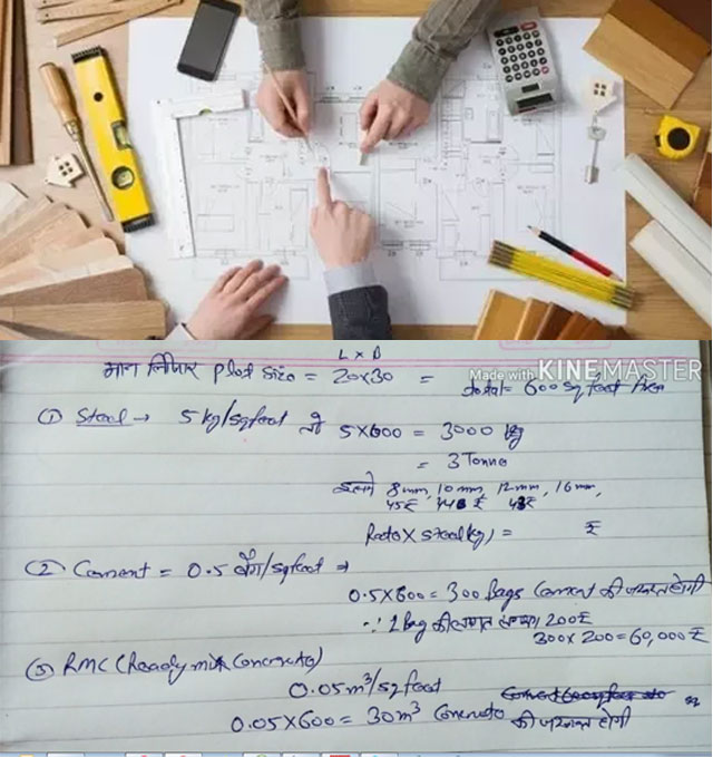
The method of working out the quantities prior to tender is a crucial test regarding what is drawn and stated can in fact be built. By examining the drawings and reviewing the construction in detail is definitely helpful in recognizing the issues which may be omitted initially.

The direct costs & indirect costs should be taken into consideration for determining the entire cost of the project which are included in various segments of the BOQ.

As the cost is identified prior to commencement of the construction, a superior level of price certainty is maintained for the construction project.

Facilitates to provide a low tender price.
Accommodates with design changes and assists the cost management process.
Provides superior quality of tender document.


Minimize the risk of contractors managing the information in the BQ for their own purposes.
Bypass the risks with regard to both time and cost since the projects are calculated on the basis of the overall floor area.
The valuation of progress payment becomes simple with detail information as given in BQ.


May pass up the tendency of contractor to build up a conspire group and bid high for projects.

Video Source: Civil Engineer

~~~~~~~~~~~~~~~~~~~~~~~~~
Published By
Rajib Dey
www.constructioncost.co
~~~~~~~~~~~~~~~~~~~~~~~~~

Thursday, December 27, 2018

Different types of thumb rules for determining the total construction cost of the building

This construction video tutorial is very useful for site engineer. In this video, one can learn how to determine the construction cost of the entire building as well as the required quantities of materials on the basis of thumb rules.

Given below the quantity and rates of materials per square feet :-


* Steel = 3 to 5 kg 
* Cement = 0.5 bags 
* RMC or ready mix concrete = 0.05 m3 
* Block = 12.5 Nos/m2 
* Electrical cost = Rs. 133 
* Plumbing cost = Rs. 126 
* Fire fighting cost = Rs. 40 
* External development = Rs. 94.5 
* Civil work structure = Rs. 751.25 
* Finishing work = Rs. 467.50

Suppose, the length of the plot is given as 20 feet

The breadth of the plot is given as 30 feet

So, the size of the plot = Length x Breadth = 20 x 30 = 600 square feet

The requirement of steel (5 kg/sq.ft) = 5 x 600 = 3000 kg = 3 Tonne

It includes 8 mm, 10 mm, 12 mm and 16 mm dia steel. The rate of 8 mm is Rs. 45/kg, 10 mm is Rs. 44/kg, 12 mm is Rs. 48/kg etc.

So, the quantity of steel = rate x steel kg

The requirement of cement (0.5 bag/sq.ft) = 0.5 x 600 = 300 bags. The cost of 1 bag is Rs. 200 (approx).

The total cost of cement = 300 x 200 = Rs. 600

The requirement of RMC alias ready mix concrete (0.05 m3/sq.ft) = 0.05 x 600 = 30 m3 cement

The cost of electricity (Rs. 133/sq.ft) = 133 x 600 = Rs. 79,800

The cost of plumbing (Rs. 126/sq.ft) = 126 x 600 = Rs. 75,600

The cost of fire alarm (Rs. 40/sq.ft) = 40 x 600 = Rs. 24,000

The construction cost with labor (Rs. 751/sq.ft) = 751 x 600 = Rs. 4,50,600

The cost of finishing work (Rs. 467/sq.ft) = 467 x 600 = Rs. 2,80,200

In finishing work interior part, exterior part and paintings are included.

To gather knowledge on other types of thumb rules, go through the following video tutorial.

Different types of thumb rules for determining the total construction cost of the building

~~~~~~~~~~~~~~~~~~~~~~~~
Published By
Rajib Dey
www.constructioncost.co
~~~~~~~~~~~~~~~~~~~~~~~~

Wednesday, December 26, 2018

Uses and advantages of digital theodolite in surveying & engineering works

In this exclusive civil engineering tutorial, you will learn the step-by-step guidelines for employing digital theodolite.

The surveyors extensively use this tool for conducting topographic survey. With this tool, it is possible to determine both the horizontal and vertical angle. By combining with stateo techniques, it can work out the horizontal distances as well as differential elevations. It is a useful tool for surveying and engineering work.

Theodolites apply caged graduated circles and angular readings are captured with an internal magnifying optical system.

The theodolite comprises of a telescope that can be moved within two perpendicular axes- the horizontal axis, and the vertical axis. The telescope is fixed and an electronic readout screen is applied to demonstrate horizontal and vertical angles. Digital theodolites are user-friendly since the digital readouts substitute the conventional graduated circles and produce more precise readings.

Instructions for use :-

Label the point at which the theodolite is going to installed with a surveyor’s nail or a stake. This point is considered as the base for calculating the angles and distances.

Arrange the tripod. The height of the tripod should be kept in such a way so that the instrument (the theodolite) remain in eye-level. The centrally placed hole of the mounting plate should remain over the nail or stake.

Push the tripod legs into the ground with the brackets on the sides of each leg.

Fix the theodolite by positioning it on top of the tripod, and screw it in exact position with the mounting knob.

Calculate the height among the ground and the instrument. It should be applied as a reference to other stations.

The theodolite should leveled by altering the tripod legs and employing the bulls-eye level. The slight tuning is done with the leveling knobs to secure t it just right.

Alter the small sight (the vertical plummet) available on the bottom of the theodolite. The vertical plummet facilitates you to perform and make sure the instrument is situated over the nail or stake. Modify the plummet with the knobs on the bottom.

Point the crosshairs in the main scope at the point to be calculated. With the help of the locking knobs on the side of the theodolite, retain it aimed on the point. Record the horizontal and vertical angles with the viewing scope available on the theodolite’s side.

Benefits of applying a Theodolite

Given below, various advantages of Theodolites:


  1. Superior correctness.
  2. Internal magnifying optical system.
  3. Reading circles is more accurate as compared to other instruments.
  4. Electronic readings.
  5. Horizontal circles are rapidly zeroed or arranged with any other value.
  6. Horizontal circle readings are captured either to the left or right of zero.
  7. Repeat readings are not required.
  8. Suitable for both flat and sloped ground.
  9. Not affected with wind or other weather factors.
Uses and advantages of digital theodolite in surveying & engineering works

~~~~~~~~~~~~~~~~~~~~~~~~
Published By
Rajib Dey
www.constructioncost.co
~~~~~~~~~~~~~~~~~~~~~~~~

Wednesday, November 14, 2018

Common types of cracks in reinforced concrete column

Usually, Four types of cracks are found in reinforced concrete column which range from diagonal cracks, horizontal cracks, splitting cracks, corrosion cracks. The cracks happen in columns due to improper design, defective construction or overloading, erosion of reinforcement, isolated settlement of foundations, creep and shrinkage.

Cracking in reinforced concrete column may result in loosing of strength, consistency, longevity, and adversely impact aesthetics.

Types of cracks found in concrete columns:

1. Diagonal Cracks: If there are diagonal cracks in reinforced concrete columns, they encircle the whole face of column anywhere along its height. Because of insufficient load bearing strength of the columns, inadequate cross-section and inadequate reinforcement steel.

Diagonal Cracks significantly impact the structural soundness and therefore it should be monitored carefully.

2. Horizontal Cracks: Horizontal crack in reinforced concrete column is generally found at the beam-column joint, and on column face where tensile stress is massive. Columns with insufficient moment resistance strength, inadequate reinforcements, or disposition of installed reinforcement may lead to horizontal cracking owning to the effect of shear force and direct load and uniaxial bending.

Finally, horizontal cracks significantly decrease the shear strength of the column and as a result there is high risk of failure. So, it should be dealt with instantly and carefully.

3. Splitting Cracks: Splitting cracks in reinforced concrete column belong to short parallel vertical cracks having non-uniform width. These types of cracks may occur in columns with insufficient steel reinforcement, and low concrete quality. Splitting cracks in concrete columns originated because of attaining its maximum load bearing strength.

The ultimate Load bearing strength of the column is exceeded when concrete cross section is not enough or reinforcement ratio is inadequate or combination thereof.

4. Corrosion Cracks: Corrosion cracks in concrete columns are formed along the line of reinforcements. These types of cracks are usually homogeneous in width and expand as the column is ageing.

Probable reinforcement erosion and insufficient bond among the concrete and steel bars lead to erosion reinforcement in concrete columns. If these types of cracks are not dealt with properly, the erosion of reinforcement will be increased at a rapid rate.

Common types of cracks in reinforced concrete column

Read more
~~~~~~~~~~~~~~~~~~~~~~~~
Published By
Rajib Dey
www.constructioncost.co
~~~~~~~~~~~~~~~~~~~~~~~~

Monday, September 10, 2018

Properties and benefits of Reactive powder concrete (RPC)

Reactive powder concrete (RPC) stands for the generic name for a class of cementious composite materials which contain superior physical properties, specifically ultra high strength and ductility.

It is formed by mixing fiber reinforced, super plasticized silica fume, cement and quartz sand along with very low water cement ratio. It contains greater compressive strength since quartz sand is applied in place of ordinary aggregate.

Composition of RPC: RPC attains it’s superior properties with a very solid mix containing fine particles and fibers.

1. Low w/cm proportion : 0.16 to 0.24 (as low as 0.13)
2. Type 20M (like type II) Portland cement (no C3A less HoH)
3. Silica fume (25% by weight)
4. Water
5. High dosage of super plasticizer
6. Fine quartz sand (SG = 2.75)
7. Steel fibers (2.5 to 10% by volume) for hardening
8. No rebar necessary


It is cured in steam bath for 48 hours @ 190 degree F (88 degree C) as soon as it is set primarily. It is set under pressure at the molding phase.

Properties of RPC:

Compressive Strength

1. Greater compressive strength as compared to HPC.
2. It is a factor connected with stability of material.
3. Highest compressive strength of RPC is roughly 200 MPa.


Flexural Strength: Plane RPC comprises of extreme flexural strength as compared to HPC (up to 100 mpa). With steel fibers, RPC can attain extreme flexural strength.

Water Absorption: The ratio of water absorption or RPC is very low than HPC. This feature of RPC supports the desired properties of nuclear waste containment materials.

Water penetrability: Water penetrability is reduced in due course of time for all mixtures. 28th day penetrability of RPC is minor than HPC (almost 7 times lower). For water absorption, the application of fibres enhance the penetrability of both types of concrete.

Defiance to chloride ion penetration: It is raised if heat curing is accomplished in concrete. Heat cured RPC demonstrates higher value as compared to normal cured RPC. This characteristic of RPC makes it perfectly fit for being used in nuclear waste containment structures.

Homogeneity: It is enhanced by removing all coarse aggregates. Dry components to be applied in RPC remains under 600 micro meter.

Compactness: Application of pressure prior to and throughout concrete setting period.

Microstructure: Microstructure of the cement hydrate is altered by providing heat treatment throughout curing.

Material Ductility: Material ductility is enhanced through the inclusion of short steel fibres.

Advantages:
1. It has the ability to structurally combat with steel.
2. It has greater stability along with shear capacity that leads to substantial dead load curtailment.
3. RPC is utilized to withstand all but direct primary tensile stress.
4. Superior seismic performance by eliminating inertia load with lighter member.
5. Low and non-interconnected porosity reduces mass transfer, keeping penetration of liquid/gas non-existent.


Properties and benefits of Reactive powder concrete (RPC)


Read more


~~~~~~~~~~~~~~~~~~~~~~~~
Published By
Rajib Dey
www.constructioncost.co
~~~~~~~~~~~~~~~~~~~~~~~~

Monday, February 19, 2018

Estimating Integration

How estimation done: Costs are generally estimated with the help of some methods that are found in Time Management idea such as one-point estimating, analogous estimating, parametric estimating and three-point or PERT estimating; besides all of this there is a different kind of estimation named method of estimation.

Bottom-up estimation is involved in the final distribution time of a project where it adds estimation of costs at each activity or work package, turning it up into control units and then finally works on whole project estimate. So the estimated created by following steps:
• Project management software: There is various kind of software that increases calculation speed needed to estimate costs and the calculations included direct, indirect, overhead and fixed cost calculations for many activities.
• Deciding resource cost rates: resources can be various kinds like human resources, vendors, consultants, suppliers, external technicians etc. and the project managers are aware about the involved rate for the resource cost.
• Reserve analysis: It gathers identification of activities with significant risks and resolution of all efforts needs to manage the occurred risks.
• Cost of quality: The quality efforts are divided as Cost of Quality.
In the time working with integration, often it is asked about estimation of interfaces that follows below kind of scenarios:
• In the New implementation of Sap, the project manager has to execute lots of interfaces to join with the previous systems
• In the B2B integration, a lot of new pattern and messages will come
• Movement from one integration broker to another.
When any of the scenarios will come interfaces are estimated by following the steps and the development is shown there:
1. Identification
2. System interactions with supported adapters
3. Specification
4. Development
5. Testing and fixing
6. Transport and configuration
7. Document
8. Going live
9. Support.
All of the steps take extra time that will expand the initial time. The 80/20 principle was invented a long ago that states that spend less time to do more work and if more time spends in the beginning of the estimation then the whole process might take longer time to end. To avoid this scenario, it is important to study about the process and understands it properly then starts the work and as there are more variations of the interfaces that look similar then it will be easy to arrange them as per order.
It must keep in mind that performing estimation is not an easy task as there will be many unknown details about development that can be seem unclear before started; so just go through them and make a detailed report.
Estimating Integration

~~~~~~~~~~~~~~~~~~~~~~~~
Published By
Rajib Dey
www.constructioncost.co
~~~~~~~~~~~~~~~~~~~~~~~~


Tuesday, November 7, 2017

Shaft3D – A powerful software for foundation design and analysis

Shaft3D software is created for simplifying the pile design process specifically for the drilled shafts or caisson type foundations. The software will allow you to perform multi tasking like shaft axial capacity analysis, lateral analysis and concrete design etc.

With Shaft3D, it is possible to design caisson foundations for windmills, transmission lines, utility lines or any other structure requiring drilled pier foundations quickly.

Shaft3D can enhance your productivity considerably through its windows-based, easy-to-learn graphical interface and its capacity to offer a complete solution for different types of analyses.
Given below, some useful features of the software :-
• International Design Codes: Compatible with various concrete design codes to finish your global projects efficiently.
• User Defined Parameters: There are various design options like shaft boundary conditions, choice of safety factors in end bearing, skin friction and pullout, choice of axial capacity methods and lot of others to fulfill numerous project specifications.
• Graphical Input of Soil Profile: Facilitates input of unrestricted number of soil layers, each with various unique set of soil properties graphically permitting you to visualize your soil profile.
• Soil Property Values: Offers a series of values of soil properties like cohesion, angle of internal friction with selection of the soil type authorizing you to complete a preliminary design devoid of detailed soil report.
• Load Cases and Combinations: Produces generally used load cases and combinations for shaft design that saves design time considerably.
• Multiple Analyses: Accomplishes axial capacity analysis, lateral analysis and concrete design in one combined surrounding.
• Axial Capacity Methods: Facilitates to choose from several axial capacity methods so that it is possible to fulfill the need of your company or client.
• Lateral Analysis: Accomplish lateral analysis with finite element analysis demonstrating vital information like deflections, shears, bending moments along the length of the shaft allowing you to explore with different “what-if” scenarios.
• Concrete Design: Execute concrete capacity design for axial loads and biaxial bending that offers you a complete geotechnical and structural solution.
• Rebar Layouts: Generates several rebar layouts with customization options.
• Material Quantities: Produces material quantities to perform precise cost estimates for your customers each time at each phase of the project.
• Detailed Design Sketches: Creates a detailed design sketch with plan, elevation and section to sum up the completed design efficiently.
• Multiple Reporting Options: Produces various types of customizable reports to utilize them for your internal or client requirements.
To know the additional features, go through the following link dimsoln.com
Shaft3D – A powerful software for foundation design and analysis

~~~~~~~~~~~~~~~~~~~~~~~~~
Published By
Rajib Dey
www.constructioncost.co
~~~~~~~~~~~~~~~~~~~~~~~~~


Monday, September 25, 2017

AStrutTie – A powerful software for structural analysis and design

HanGil IT is the developer of AStrutTie, a powerful software for creating perfect structural design. It is primarily applied to make analysis and design a strut-tie model for concrete members which contain disturbed stress region(s).

It facilitates the users to create the design of corbel (bracket), abutment/pier footing, bridge pier coping (pier cap), frame corner, anchorage zone, deep beam, etc. The software is compatible with U.S (ACI 318, AASHTO LRFD) and Europe (EuroCode 2) codes and specifications.

A concrete member is categorized as B-region(s) and D-region(s). D-regions belong to parts of structure in which the strain distribution is extremely nonlinear. The design practices for D-regions are generally dependent on empirical approaches. The strut-tie model approach produces a superior concept concerning load transfer mechanisms as well as structural behavior and it empowers the designer to deal with unconventional situations including D-regions.
AStrutTie is a handy software for making analysis/design of concrete members having D-region(s). The most perfect strut-tie models are developed based on the principal stress flows and/or evolutionary structural optimization (ESO) results.
AStrutTie comprises of a specialized solver that can efficiently manage any sorts of internally/externally (in) determinate strut-tie models. The strut-tie model provisions of ACI 318-14 (2014), AASHTO LRFD (2014), and EC2 (2004) are employed.
In order to make quick and efficient strut-tie model designs, multirole templates are arranged for corbel (bracket), abutment footing, pier footing, bridge pier coping (pier cap), frame corner, anchorage zones with inclined and straight tendons, and deep beams with concentrated and distributed loads.
The shapes of concrete members and truss models are also formed by importing .dxf files. Advanced element sets illustrating truss mechanism, truss and arch mechanism, and fan action are arranged.

AStrutTie offers different automated design checks reclassifying the conditions for rebar necessity and strength validation of struts and nodal zones. Visual validations of strength conditions can also be done.
A structural design report is automatically created, and design results are evaluated by forecasting the report. The structural design report is printed as a .rtf or .xlsx file.

Click on the following link to download the software www.concretenetwork.com


~~~~~~~~~~~~~~~~~~~~~~
Published By
Rajib Dey
www.constructioncost.co
~~~~~~~~~~~~~~~~~~~~~~

Wednesday, September 6, 2017

RetainWall version 2.60 – A powerful software for designing a concrete or masonry retaining wall

Dhani Irwanto has developed RetainWall. It is an exclusive software that can be used for making the design of a concrete or masonry retaining wall. The wall may preserve soil or other granular material.
It examines the strength of the wall on the basis of the loads and resistances, and leads to bearing pressure, sliding, overturning and rotational stabilities. Loads which operate on the wall may include self weight, soil pressure, water pressure, live and seismic loads.

Resistances may contain base friction and cohesion, passive earth pressure, other structures or a shear key. Load and resistance factor design (LRFD) mode can be employed. If the wall is a reinforced concrete structure, the software can also produce the reinforcement design for any reinforced concrete structure wall. Besides, there is a soil pressure calculator.
This user-friendly application provides on-screen trial-and-error method and instant solution for the design. With it, any designer will be able to design the wall swiftly. Complete outputs are visible on screen or printed.
The software starts it’s operation by clicking on the specified dimensions to produce the initial dimensioning of the wall, earth surface and water levels. After that, it enters material properties of the wall, soil, water and reinforcement bars. Provided external loads contain surcharge load, seismic load as a horizontal seismic coefficient and any concentrated loads implemented on the wall if necessary. Load and resistance factors combinations are easily selected. Results of the wall stability are gained immediately. If satisfactory result is not obtained, then another trial can be produced instantly. You can also choose from options to use or not to use water, seismic or ashear key. The final results can also be printed.
The reinforced concrete design can be made instantly by applying the internal forces of the wall. It only needs bar diameters and spacings of the reinforcements.
RetainWall is compatible with metric, SI and British unit systems.
Given below, some exclusive features of the software :-
a. Ability to design Load and resistance factors.
b. Apply load and resistance factors combinations from AASHTO LRFD 2007, ACI 318-08 and IBC 2006.
c. Load and resistance factors editor to change or generate new combinations
d. Concrete reinforcement design from ACI 318-08.
e. Force diagrams (moment, shear and normal) for every combination.
f. Loads, resistances and reactions diagrams for every combination.
g. Wall stabilities (bearing, sliding, overturning, rotation) for every combination.
h. Workout nominal soil bearing resistance by applying theoretical or semi empirical methods.
i. Ability to select active or at rest soil pressures.
j. Ability to select elastic (rock) or plastic (soil) bearing pressures.
k. Ability to enter user's soil pressure coefficients.
l. Reinforcement design for upper stem, lower stem, toe and heel.
m. Unit systems, properties, load and resistance factors, reinforcement design method, and page setup from last editing which turn out to be the default for new design.
n. Ability to include other loads on wall.
o. Offer stability resistances from a shear key, toe passive soil pressure, adjacent structure, anchors or piles.
p. Enable or disable a shear key, water or seismic.
q. Various types of units of measurements like metric, SI and British unit systems are supported.
r. Easy, clear, quick and simple software operation.
s. Help facilities, can be printed to produce manual.

Click on the following link to download a trial version RetainWall version 2.60

RetainWall version 2.60 – A powerful software for designing a concrete or masonry retaining wall


~~~~~~~~~~~~~~~~~~~~~~
Published By
Rajib Dey
www.constructioncost.co
~~~~~~~~~~~~~~~~~~~~~~

Tuesday, September 5, 2017

RebarWin – A powerful software for rebar detailers

RebarWin is a powerful construction program that can be used for rebar detailing. The software is specifically designed for rebar detailers who are involved in construction and civil engineering projects.
The users can select through different types of measuring systems (As for instance US Imperial and Softmetric, European metric.
Given below, some major features of RebarWin:
• Produces sorted, weighed and compiled bar lists.
• Prints labels should be attached with the rebar bundles.
• Compatible with Imperial, SoftMetric and European Metric Measuring Systems.
• Exports to Excel® SpreadSheet.
• Either bar lists and labels are categorized (and in what order), weighed and/or accumulated is settled by the user when they are printed.
• Preserves standard bend shapes in databases to avail them smoothly and automatically. A primary collection is integrated that will be visible in the samples page.
• The placing requirements can be described with graphics. All rebar necessary in a structure can appear jointly in the bar list and in the same label, in a superior-quality placing drawing. To define high complexity structures properly, bar list and label paper sizes should be raised. These structures are preserved in databases with the purpose of not redrawing them each time.
• Estimates bending dimensions out of other identified dimensions.
• Works out straight and bent varying bars.
• If necessary, employ bending deductions to shearing length and/or weight is determined by the user when bar lists, labels or statistics are printed.
• The length/weight relation and bending deductions are easily modified and have to be configured separately for various machines.
• Rebar Orders are arranged according to projects and units. A list and total weight for all the orders in a project, unit, type or date range can be easily acquired.
• Produces statistical reports. Information can also be obtained on how much has been bent and how much has persisted straight for each diameter and machine, and that in a specified project, unit, type or date range.
• The previous features are provided in the 60-day trial shareware version, that can be downloaded at free of cost. The following, export / import and network sharing, are only accessible to registered users.
• Export Orders (bar detailing lists) and Models (bend types) to a file so as to deliver them by e-mail or diskette to another computer. With export / Import options the detailers will be able to work on the similar project in various locations.
• Network sharing.
• If required, any modification can be done to the program.

To download the program, click on the following link www.rebar.net

How concrete strength is impacted with different factors


~~~~~~~~~~~~~~~~~~~~~~
Published By
Rajib Dey
www.constructioncost.co
~~~~~~~~~~~~~~~~~~~~~~