adsense analytic

Friday, April 28, 2017

Different methods to strengthen the masonry walls

Strengthening of masonry walls is required to prevent failure and collapse during major earthquake or addition of extra load on buildings. Strengthening of masonry walls also may be required during rehabilitation of buildings.
Due to severe earthquake or inclusion of additional weight on buildings, the building may fall or collapse. To get rid of this type of issue, the masonry walls should be reinforced perfectly. Reinforcing of masonry walls is also needed throughout rehabilitation of buildings.
Unreinforced masonry walls contain sufficient compressive strength, but they are breakable and very fragile under the influence of lateral loads which lead to tension in walls. On every occasion, tension forces operate on a masonry wall, it has a tendency for being cracked.
Cracking of masonry walls happen because of foundation settlement, all through earthquakes, employment of lateral loads. Cracking for masonry wall may occur for different reasons but these can lead to collapse of wall entirely.
Under load bearing masonry buildings, loads from the building is delivered through walls and failure and collapse of such masonry walls can result in collapsing of the entire building.
For reinforced concrete framed structures, though loads are delivered through columns, but if any earthquake occurs, these walls may develop cracks and fall.
Generally half brick thick masonry walls are applied as partitions in the interior of RC framed buildings. These half brick masonry walls are insecure to withstand the lateral forces throughout earthquake. Beyond plane strengthening of partitions can be accumulated jointly with lateral strengthening of building by arranging reinforced concrete jackets to the partitions.
To resist the collapsing of masonry walls throughout earthquake, it is recommended to utilize reinforced brick masonry walls in new construction. Prevailing masonry walls are also reinforced with the use of reinforced concrete jackets on one or both sides of the walls.
Masonry Wall Strengthening Process:

The following processes are applied to strengthen Masonry walls:
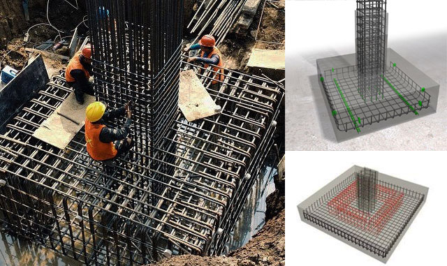
1. Arranging reinforced concrete jackets on one or both faces of walls.
2. Apply FRP Structural Repointing for strengthening of masonry walls.

To read the complete article, go through the following link 
concretecivil.com

Different methods to strengthen the masonry walls

~~~~~~~~~~~~~~~~~~~~~~~~
Published By
Rajib Dey
www.constructioncost.co
~~~~~~~~~~~~~~~~~~~~~~~~

Thursday, April 27, 2017

Brief overview of working stress design & its parameters

This article is extracted from an exclusive construction article written by Noel Mades, a renowned civil engineer. The article sheds light on working stress design and its criterions.
Working stress design is a useful design process in which structures or members are well-balanced toward prearranged working loads at stresses which are under their ultimate values; linear distribution of flexural stresses is accepted.
It’s a customary method applicable for reinforced concrete design (beams, slabs, columns, footing etc.) where concrete is supposed to be elastic, steel and concrete which act elastically in an organized way where the relationship among loads and stresses is linear.
Working Stress Design refers to the proportion among modulus of elasticity of steel and concrete. This conservative method of design greatly impacts modern structural design.
It is also dependent on the elastic theory under which the materials, concrete, and steel are supposed to be stressed properly beneath their elastic limit under the design loads.
Given below, the criterions of working stress design.
1. Stress-Strain Diagram
It is a diagram that demonstrates the stress and strain relationships as well as the elastic limit where the young's modulus is used and defined as the "elastic region" happens. The yield point, ultimate tensile stress, and the point of fracture are also specified.

To gather more information, go through the following link. nolmads.blogspot.com

Brief overview of working stress design & its parameters

~~~~~~~~~~~~~~~~~~~~~~~~
Published By
Rajib Dey
www.constructioncost.co
~~~~~~~~~~~~~~~~~~~~~~~~

Wednesday, April 26, 2017

How to use Mohr’s Circle to find out shear stresses & principal stresses

This construction video tutorial is based on Mohr's Circle Maximum Shear Stress & Principal Stresses SOM.
Christian Otto Mohr, a renowned civil engineer, has developed Mohr Circle. This exclusive graphical method can be used by designer to find out principal stresses.
Mohr Circle stands for a two-dimensional graphical illustration concerning the transformation law toward the Cauchy stress tensor.
Mohr's circle reveals the principal angles (orientations) concerning the principal stresses devoid of plugging an angle into stress transformation equations. It proceeds with a stress or strain element in the XY plane, builds a grid with a normal stress on the horizontal axis as well as a shear stress on the vertical.
This graphical representation is very valuable as it facilitates you to foresee the relationships among the normal and shear stresses operating on different inclined planes at a point in a stressed body.

Mohr’s Circle is used to measure principal stresses, maximum shear stresses as well as stresses on inclined planes.


How to use Mohr’s Circle


Read more

~~~~~~~~~~~~~~~~~~~~~~~~
Published By
Rajib Dey
www.constructioncost.co
~~~~~~~~~~~~~~~~~~~~~~~~

Tuesday, April 25, 2017

Some useful tips for machine foundation design

Before starting the detailing work for foundations, the following general needs concerning machine foundations should be fulfilled and the results should be verified.
1. The foundation should have contained the capacity to bear the superimposed loads devoid of producing shear or crushing failure.
2. The settlements should have been inside the allowable limits.
3. The amalgamated centre of gravity of machine and foundation should have been maintained in the equivalent vertical line like the centre of gravity of the base plane.
4. There should have been no resonance, therefore the normal frequency of the foundation–soil system should have been either too big or too small with regard to the operating frequency of the machine. Toward low-speed machines, the natural frequency should have been high.
5. The amplitudes under service conditions should be maintained under allowable limits which are recommended by the machine manufacturers.
6. All rotational and correlating parts of a machine should be well-adjusted efficiently with the purpose of reducing the unbalanced forces or moments.
7. If necessary, the foundation should be planned in an efficient way with the intention of allowing a consequent adjustment of natural frequency by adjusting the base area or form of the foundation as may be essential afterward.

To read the complete article, go through the following link. theconstructor.org

Some useful tips for machine foundation design


~~~~~~~~~~~~~~~~~~~~~~~~
Published By
Rajib Dey
www.constructioncost.co
~~~~~~~~~~~~~~~~~~~~~~~~

Monday, April 24, 2017

Derivation of area of circle

This construction video will provide brief information on the formula derivation toward circle area. To estimate the area of a circle, the formula A=(πR^2) is applied. You will gather knowledge on the origin of the formula and the importance of it.
Here π stands for the ratio of the diameter of a circle to its circumference, and stands for the radius of the circle.
In geometry, the area surrounded with a circle of radius r is πr2. Here, π symbolizes a constant, roughly equivalent to 3.14159, that is the same as the ratio of the circumference of any circle to its diameter.

Go through the following video, to get the detailed process.


Read more

~~~~~~~~~~~~~~~~~~~~~~~~
Published By
Rajib Dey
www.constructioncost.co
~~~~~~~~~~~~~~~~~~~~~~~~


Friday, April 21, 2017

Fundamentals of Residential Construction 4th Edition – An exclusive ebook by Alexander C. Schreyer

Edward Allen, Rob Thallon and Alexander C. Schreyer have jointly published an exclusive construction e-book alias Fundamentals of Residential Construction. The book provides detailed guidelines on the each step of construction process for building up single family and multifamily home building. This book sheds light on each and every step associated with home construction which range from siting and foundations to finishing details. The book is enriched with more than 1,200 drawings and photographs whereas collaborative accompanying online resources facilitate in getting an overview of the material. This latest publication highlights the newest improvements in materials and methods, along with new coverage of sustainable building and energy efficiency, multifamily construction, prefabricated building components, and CAD/BIM planning tools in residential construction. Important exposure on wood light-frame construction, building systems, industrialized fabrication, insulating concrete forms, light-gauge steel and masonry construction, multi-family buildings, and more offers a solid understanding of residential construction methods, tools, and processes.
While constructing a home, sound knowledge is necessary for materials, structures, codes, and management processes as these can help in arranging the preparation of expertise essential for finishing a residential project successfully.
·         Be familiar with the pros and cons of common materials and systems
·         Gather knowledge on site preparation, foundations, and framing
·         Dip into the details of roofing, finishing, and energy efficiency
·         Recognize heating/cooling, plumbing, and electrical options
·         Explore through the newest codes, costs, and management best practices

Bar bending schedule offers the steel quantity requirement in a better way and thus delivers an option to make optimal use of the design in case of cost overflow.
The process becomes simple for site engineers to validate and approve the bar bending and cutting length throughout inspection prior to positioning of concrete with the support of bar bending schedule and thus facilitates in superior quality control.
It becomes easier to handle the reinforcement stock necessary for identified time duration.
It will facilitate to fabrication of R/F with structure.

Buy the book online from Amazon by clicking on the following link 
Buy Now


~~~~~~~~~~~~~~~~~~~~~~~~
Published By
Rajib Dey
www.constructioncost.co
~~~~~~~~~~~~~~~~~~~~~~~~
Fundamentals of Residential Construction


Download Bar Bending Schedule Of Box Culvert

Definition of Bar bending
It is the method of bending reinforcing steel into shapes which are important for reinforced concrete construction.
Definition of Bar bending schedule(BBS)
Bar bending schedule alias schedule of bars refers to a list of reinforcement bars, a specified RCC work item that is shown in a tabular form for a smooth view. This table sums up all the necessary particulars of bars ranging from diameter, shape of bending, length of each bent and straight portions, angles of bending, total length of each bar, and number of each type of bar. This information can be used for making an estimate of quantities.
It includes all the details essential for fabrication of steel like bar mark, bar type and size, number of units, length of a bar, shape code, distance between stirrups (column, plinth, beam) etc.
While generating bar schedules, it is important to take proper care about length. In case of bending, bar length will be raised at the bending positions.
Benefits of the Bar Schedule:
When bar bending schedule is applied along with reinforcement detailed drawing, it makes the quality of construction superior.
Once bar bending schedule is prepared, cutting and bending of reinforcement is performed at factory and shipped to job site. This improves quick implementation at site and minimizes construction time and cost as fewer workers are needed for bar bending. Bar bending also circumvents the wastage of steel reinforcement (5 to 10%) and thus project cost is saved significantly.
It offers the perfect estimation of reinforcement steel requirement for all the structural members which are applied to workout complete reinforcement requirement for whole project.
Bar bending schedule offers the steel quantity requirement in a better way and thus delivers an option to make optimal use of the design in case of cost overflow.
The process becomes simple for site engineers to validate and approve the bar bending and cutting length throughout inspection prior to positioning of concrete with the support of bar bending schedule and thus facilitates in superior quality control.
It becomes easier to handle the reinforcement stock necessary for identified time duration.
It will facilitate to fabrication of R/F with structure.

To download the excel sheet for bar bending schedule, click on the following link 
Download Sheet


Download Bar Bending Schedule Of Box Culvert


~~~~~~~~~~~~~~~~~~~~~~~~
Published By
Rajib Dey
www.constructioncost.co
~~~~~~~~~~~~~~~~~~~~~~~~

Thursday, April 20, 2017

Reasons for failure of bearing capacity on foundation

Foundation failure occurs due to variation on the load:
There exist three types of shear failure, i.e. General, Local and Punching shear failures which happened due to the compactness of soil and depth of footing with regard to its breadth (i.e D/B Ratio). When the utmost capacitybearing  of the soil is attained, it may fail in one of the following three failure type on the basis of the type of soil and depth to width ratio of the footing. A foundation can collapse in the following three diverse ways under loads :
Punching shear failure of foundation
General Shear Failure of foundation
Local shear failure of foundation
The above three types of foundation failure should be examined throughout design phase of concrete foundation for the specified load. Directives obtained through standard codes of practice should be obeyed so that foundation does not fail in any of the failure types as stated under any probable load combinations when structure is in use.
1.General Shear Failure
  • Under this type, the footing moves downward slightly and thus forms completely plastic zones and a sudden failure occurs with a significant bulging of the ground surface alongside the footing
  • It is based on clear-cut failure pattern, that comprised of a wedge and slip surface and bulging (heaving) of soil surface alongside the footing
  • Sudden collapse happens, together with tilting of the footing
  • This type of failure happens provided that dense sand or stiff cohesive soil support the footing
  • Failure load is apparent
  • The load-settlement diagram is equivalent to stress-strain for solid sand or over-consolidated clay
  • The ultimate load is apparent on this curve.
2. Local shear Failure:
Failure pattern comprises of wedge and slip surface but is transparent only under the footing. Slight bulging of soil surface takes place. Tilting of footing is not necessary.
  • In this mode a large deformation takes place under the footing prior to the formation of failure zones, i.e. large vertical settlement occurs prior to slight bulging of the ground surface
  • Tilting of footing is not necessary
  • Ultimate load is not clear
  • It occurs in moderately compressible soils or loose sand i.e occurs in soil of high compactness
  • Yielding occurs adjacent to the lower edges of the footing
  • Various yield developments may happen together with settlement in a series of jerks
  • The bearing pressure at which the first yield occurs is assigned as the first-failure pressure or first failure load
Reasons for failure of bearing capacity on foundation


~~~~~~~~~~~~~~~~~~~~~~~~
Published By
Rajib Dey
www.constructioncost.co
~~~~~~~~~~~~~~~~~~~~~~~~

Wednesday, April 19, 2017

How to work out cutting length for column circular stirrups

This construction video is recorded to provide you some useful tips for estimating the cutting length of the circular column stirrups.
Here the radius of the column is taken as 400 mm.
Dia of stirrup is taken as 8 mm
Concrete Cover is taken as 40 mm
Stirrups are also known as Links or Rings or Transverse Reinforcement. Stirrups are applied in Beams and Columns. The stirrups remain vertical in a beam and horizontal in a column.
Benefits of column stirrups :
To settle and withstand the longitudinal (main) steel bars in columns to bulging below the vertical forces (compression force) particularly in the middle of the column prior to get to the concrete.
Increase the quantities (diameter or by spacing) of stirrups at both ends of the column with the intension of combating the horizontal forces which produce horizontal shear forces on both ends of the column.
Go through the following video, to get the detailed process.


~~~~~~~~~~~~~~~~~~~~~
Published By
Rajib Dey
www.constructioncost.co
~~~~~~~~~~~~~~~~~~~~~

Tuesday, April 18, 2017

How to use method of joints for perfect truss analysis

This construction video tutorial is based on method of joint required for perfect truss analysis. (detect forces in various members of truss).

Trusses belong to structures which are extensively applied in various civil engineering applications like bridges, steel buildings and roof structures.

The method of joints is the most recognized process to discover unidentified forces in a truss structure. Under this process, all forces functioning on a joint must add to zero. If there exist a net force, the joint will shift. When a truss remains in equilibrium, then each of its joints should be in equilibrium. The method of joints comprise of satisfying the equilibrium equations for forces working on each joint.

Go through the following video, to get the detailed process.

How to use method of joints for perfect truss analysis

Read more

~~~~~~~~~~~~~~~~~~~~~~~~
Published By
Rajib Dey
www.constructioncost.co
~~~~~~~~~~~~~~~~~~~~~~~~

Monday, April 17, 2017

Download online construction estimate calculator to estimate the quantities of materials

The absolute volume method is used to work out the material quantities for forming the necessary quantity of concrete on the basis of specified mix proportions. This method is formulated following the principle that the volume of fully compacted concrete is equivalent to the absolute volume of all the materials of concrete consisting of cement, sand, coarse aggregates and water.

Depending on the type of structure, a concrete structure may contain beams, slabs, columns and foundations etc. The volume of concrete essential for concrete structure is computed by summation of the volumes of every structural member or each parts of the members. The formula for computing the volume of a rectangular cross sectional member is length x width x height (or depth or thickness). Appropriate formula should be applied for various cross-sectional shapes of members.


Download construction estimate calculator


~~~~~~~~~~~~~~~~~~~~~~~~
Published By
Rajib Dey
www.constructioncost.co
~~~~~~~~~~~~~~~~~~~~~~~~


Friday, April 14, 2017

How to draw SFD and BMD of one sided overhand beam

This construction video provides some useful guidelines for creating the drawing of SFD and BMD for one sided overhanding beam with point loads.
Shear force and bending moment diagrams are represented as SFD and BMD. These are called as analytical tools and applied in combination with structural analysis to facilitate carrying out structural design by ascertaining the value of shear force and bending moment at a specified point of a structural element like a beam.
The structural engineers or other construction professionals, who handle forces in materials, utilize bending moment and shear diagrams. While designing steel beam the structural engineer can easily find out lightest shape through bending moment that can be applied to transmit this bending moment. In any case, steel stirrups are arranged in concrete beams every time.
These diagrams are also very useful in any actual situation, where it is required to compute the stresses in a bending moment. These diagrams help in finding out the type and size of a member of a specified material easily. Besides, the deflection is detected easily with either the moment area method or the conjugate beam method.
Go through the following video, to get the detailed process.
How to measure the quantity of asphalt in road construction


~~~~~~~~~~~~~~~~~~~~~~~~
Published By
Rajib Dey
www.constructioncost.co
~~~~~~~~~~~~~~~~~~~~~~~~

Thursday, April 13, 2017

How to measure the quantity of asphalt in road construction

This construction video shows the detailed process for measuring the quantity of Asphalt in road.
Asphalt belongs to a blend of aggregates, binder and filler. It is mainly applied for developing and preserving all kind of roads, parking areas as well as play and sport areas. Various types of aggregates like crushed rock, sand, gravel or slags are utilized as mixtures of Asphalt. A binder is applied with the purpose of fastening the aggregates into a solid mixture. Generally, bitumen is utilized as a binder. An average asphalt pavement comprises of the road structure over the formation level that contains unbound and bituminous-bound materials. So, the loads of the traffic are dispersed through the pavement earlier it reaches to the formation level. Generally, pavements are formed with different layers.
Here, the dimensions of the road are given as follow :-
Breadth = 8 meter
Depth of the road = 15 centimeter
Length = 2 km = 2000 meter
Therefore, the volume of asphalt = L x B x W = 2000 x 8 x 0.15 (15 cm = 0.15 m) = 2400 m3
Here, density of asphalt is taken as 2330 kg/m3
Therefore, quantity of asphalt = volume of road section x density of asphalt
= 2400 x 2330 = 559200 kg = 5592 tons (dividing by 1000)
Go through the following video, to get the detailed process.


~~~~~~~~~~~~~~~~~~~~
Published By
Rajib Dey
www.constructioncost.co
~~~~~~~~~~~~~~~~~~~~~

Wednesday, April 12, 2017

On site demonstration on setting up formwork for concrete beam construction

Formwork in concrete construction is nothing but a mold for a structure where fresh concrete is poured with the purpose of solidifying it consequently. Formwork is temporary structure and generally it is not demonstrated in the drawings. Types of formwork for concrete construction are based on the material of formwork as well as type of structural element.
Formworks is also categorized on the basis of the type of structural member construction like slab formwork to be applied in slab, beam formwork, column formwork to be applied in beams and columns respectively.
Formwork Materials.
• Wood
• Either all-wood or some wood components
• Plywood
• Aluminum
• Steel
• Plastics
In this construction video tutorial, one can learn how to arrange formwork for concrete beam construction.
Beam formwork is generally formed with either timber or metal panels. In this type of formwork, the process is to produce a box surrounded with frames at the perfect size of the beam and fasten it firmly on the kicker left from base or at the last phase of beam concreting. The box is detained in exact position with steel column clamps or bolted yokes and supported with timber studs or props.
Consideration should be given on the following points for formwork construction It is hard enough to resist all types of dead and live loads.
It should be built up tightly and sustained competently and braced both horizontally and vertically with the intension of preserving its shape.
The joints in the formwork should be firm against seepage of cement grout.
The formwork should be arranged correctly to the preferred line and levels with plane surface.
The material of the formwork should not be twisted when comes in contact with the elements.
It should be supported with firm base.


~~~~~~~~~~~~~~~~~~~~~
Published By
Rajib Dey
www.constructioncost.co
~~~~~~~~~~~~~~~~~~~~~

Tuesday, April 11, 2017

How To Arrange Bar Bending Schedule For RCC Beams

This construction video tutorial is based on BAR BENDING SCHEDULE FOR RCC BEAM.
From bar bending schedule, one can get the reinforcement calculation for reinforced concrete beam. It gives us details of reinforcement cutting length, type of bends and bend length.
In this construction video, solution is given for two beams having spans of 6 meter. 1st layer of bottom bar of beam is 32 dia and 2nd layer that is called bottom extra is 25 dia.
1st layer of top bar of beam is 25 dia and US bar (extra cover support in second layer) is 25 dia.
Clear cover = 30 mm
Development length = 50 dia
Lapping = 50 dia
To have the complete calculation process, go through the following video

How to arrange bar bending schedule for RCC Beams

~~~~~~~~~~~~~~~~~~~~
Published By
Rajib Dey
www.constructioncost.co
~~~~~~~~~~~~~~~~~~~~

Monday, April 10, 2017

How does water play an important role in concrete?

In order to develop concrete, binding materials and inert materials are amalgamated with water. Therefore, the quality of concrete is dependent on the water and its quality as well as quantity. Water to cementitious materials ratio in concrete is most vital to ascertain the strength and longevity of concrete.
Water is essential to drench the surface of aggregates to form adhesive quality because the cement paste affixes instantly and suitably to the wet surface of the aggregates as compared to a dry surface. Also water plays a vital role to produce plastic mixture of the different components with the purpose of passing on workability to concrete so that it can be arranged in the preferred position. In due course, by making a chemical reaction with cement, water facilitates to form the desirable properties of the concrete.
Generally, consideration is not given to the quality of the water though water is very vital to detect the strength of the final product. It is a general conception that any potable water is ideal for being applied in concrete formation. But, if only non-potable water is usable, it is suggested to check the water to determine its contents and acquire necessary steps to provide possible adversarial effects on the final concrete.
Though water with little acidic nature is not harmful, but highly acidic or alkaline water must not be used as it may provide adversarial effect over the reinforcing of concrete. Water blended with algae should not be used as such water may lead to entrainments which sequentially can reduce the concrete strength. It is observed that sea water minimizes the long-lasting strength of the cement, though it is calculated to be just 15%. Water containing If, huge amount of chlorides are included in water, it results in creating perpetual dampness and surface efflorescence and also corrosion of steel utilized in concrete.
Thus, the available chemical components in water may actively form the chemical reactions and thus influence the setting, hardening and strength development of concrete. So, it is recommended to verify the quality of water in order to maintain the superior quality of concrete.
How does water play an important role in concrete

~~~~~~~~~~~~~~~~~~~~~
Published By
Rajib Dey
www.constructioncost.co
~~~~~~~~~~~~~~~~~~~~~


Friday, April 7, 2017

Design specifications for footings following IS 456: 2000

As per standard IS 456: 2000, the following guidelines are given for the design of isolated footings :-
The objective of Footings is to retain the applied loads, moments and forces and the driven reactions and make sure that any prospective settlement is as almost undeviating as possible, and the safe bearing capacity of the soil is not surpassed.
In sloped or stepped footings the operative cross-section in compression is restricted with the area over the neutral plane as well as the angle of slope or depth and location of steps is arranged in such a way that the necessities for design are fulfilled at each section. Sloped and stepped footings which are designed as a unit should be built up to guarantee action as a unit.
Thickness at the Edge of Footing
1. In reinforced and plain concrete footings, the thickness at the edge should be over 150 mm for footings on soils, nor below 300 mm over the tops of piles for footings on piles.
2. For plain concrete pedestals, the angle among the plane moving toward the bottom edge of the pedestal and the equivalent junction edge of the column with pedestal and the horizontal plane should be managed by the expression:
2) where
= computed optimal bearing pressure at the base of the pedestal in N/mm2
fck = characteristic strength of concrete at 28 days in N/mm2.
Moments and Forces
1. Toward the footings on piles, calculation for moments and shears are dependent on the proposition that the reaction from any pile is set at the centre of the pile.
2. In order to calculate stresses in footings which support a round or octagonal concrete column or pedestal, the face of the column or pedestal is assumed as the side of a square imprinted within the perimeter of the round or octagonal column or pedestal.
Specification For Footing

~~~~~~~~~~~~~~~~~~~~~~~~
Published By
Rajib Dey
www.constructioncost.co
~~~~~~~~~~~~~~~~~~~~~~~~

Thursday, April 6, 2017

How to design a sewer line pipe

This construction video tutorial sheds light on the methods for sewer line or sewer pipe as well as different types of sewer pipe.
Based on the section, sewer pipe comes in different shapes like circular and semi circular sewer pipe, rectangular sewer pipe, elliptical sewer pipe, egg shaped sewer pipe, basket handle sewer pipe, horse shoe sewer pipe.
Here, the calculation for design is shown for each type of sewer pipe mentioned above.
In first example, the method is demonstrated for designing a circular sewer pipe that offers average discharge equivalent to 40 litre/sec. Sewage velocity is 1.5 m/sec.
The following formula is used for design calculation :-
Maximum flow of sewage = 40 x 3 (here 40 denotes average discharge)
N.B. In order to transform average discharge into maximum discharge, it is require to multiply the average flow with 2 or 3 that is recognized as multiplying factor.
Therefore, after multiplication, the result is = 120 litre/sec.
Now, convert the unit of litre into cubic meter by dividing it with 1000
The result is = 0.12 m3/sec, it is also called as cumec
Therefore, maxium flow = 0.12 cumec
But with this, the sewer pipe can flow upto 2/3 but for designing the sewer for full flow, the following method should be applied.
Full flow = 0.12 x 1.5 = 0.18 cumec (1.5 is obtained by dividing 3 by 2)
To get more information, go through the following video.

How to perfectly lay blocks for a brick wall


~~~~~~~~~~~~~~~~~~~~~~
Published By
Rajib Dey
www.constructioncost.co
~~~~~~~~~~~~~~~~~~~~~~

Wednesday, April 5, 2017

Estimator Required - Formwork & Concrete Structure contractor

A renowned and 15 years old formwork & structures contractor located in Melbourne's Western suburbs, is seeking an experienced, methodical and perfect estimator on permanent basis to work in tandem with estimating manager of the company.
Eligibilities :-
Should have at least 2 years of working experience in a commercial.
structures/formwork environment (either main contractor or sub-contractor side) Should contain sound knowledge and capability for pricing formwork systems, concrete, groundworks etc.
Should be good technical savvy and contain the ability for reading and annotating structural drawings.
Should have the capacity to estimate precisely and prepare full BOQ.
Should have the capability for transactional contract administration like progress claims and variations management.
Should be a self motivated person and have the ability for working devoid of micro-management.
Salary will be offered on the basis of the experience that ranges from $70,000 - $110,000.
The interested candidates can send their CV in word format to Jono Conley at Constructive Recruitment by clicking on the following links.
N.B.: Only nominated candidates will be contacted directly.
Formwork & Concrete Structure contractor

~~~~~~~~~~~~~~~~~~~~~~~~

Published By

Rajib Dey

www.constructioncost.co

~~~~~~~~~~~~~~~~~~~~~~~~