adsense analytic

Showing posts with label Bar Bending. Show all posts

Tuesday, March 31, 2020

Different types of BBS shape codes for steel

Sami Ullah, the renowned civil engineer, presents this useful video tutorial in civil engineering youtube channel. In this video, the detail process is given for finding out the quantity of steel as well as shape codes for the steel bars.

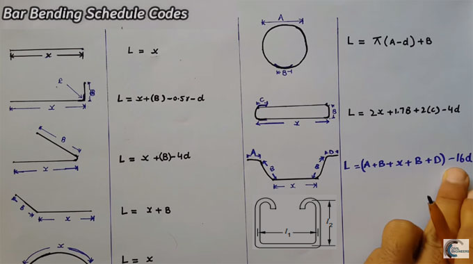
Shape codes are considered as the basis of a proper bar bending schedule.

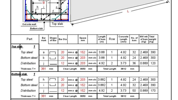
While going to estimate the reinforcement detailing for various members concerning a building, small bent ups and other angle detailing should be considered in the calculation to produce valid and cost-effective bar bending schedule.

It will significantly reduce the cost and wastage of reinforcement.

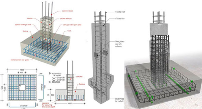
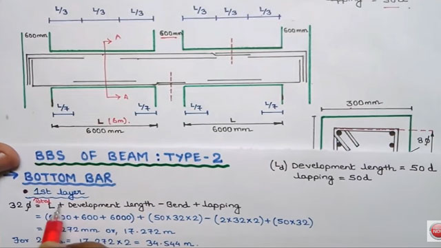
In beams & slabs there exist various bent ups, cuttings, and development lengths. Each and every bend and angle presented in the member is the outcome of design calculation. Therefore, these should be carefully enforced in practice.

For small projects, it is unnecessary to compute these details, just include a few more inches and work out the Bar Bending Schedule.

Different types of BBS shape codes for steel

~~~~~~~~~~~~~~~~~~~~~~~~~~
Published By
Rajib Dey
www.constructioncost.co
~~~~~~~~~~~~~~~~~~~~~~~~~~

Friday, August 30, 2019

Guidelines for rebar detailing of RCC structures

Reinforcement Detailing or Rebar detailing is a detailed construction engineering process normally accomplished by the Rebar fabricators, structural engineering consultants or the contractors for generating ‘shop/placing’ drawings or shop drawings and bar bending schedule of steel reinforcement for construction. Architect/Engineers(A/E) produce ‘Design Drawings’ with the purpose of adding strengths with rebar size, spacing, location, and lap of steel.

Rebar Detailing is also known as Rebar scheduling, RC Detailing and Bar Bending schedule predation, RC Drafting, etc in different countries.

Objective of Rebar Detailing - The rebar detailing is done for the following purposes :

a) To produce an error-free Bar bending schedule, when fabricated should be accommodated in the concrete formwork devoid of any issue. The similar Bar Bending Schedule should be utilized for accounting and invoicing.

b) To develop a detailed Rebar placing drawing (known as Rebar Shop drawings). This Rebar placing drawing assists an Ironworker to place rebar perfectly in the site efficiently.

c) To allow the structural engineer to verify and approve when the structural design intent is precisely transformed into the Rebar Placing drawings and Bar bending schedules.

d) To perform a Rebar wastage analytics and minimize probable scrap existing in the Drawing level.

Standard Hooks: The term “standard hook” is defined as follow -

1. 180o bend together with an extension of minimum 4 bar diameters, but not below 65 mm at the free end of the bar.
2. 90o bend together with an extension of minimum 12 bar diameters at the free end of the bar.
3. For stirrup and tie anchorage.


For 16 mm φ bar and smaller, a 90o bend along with an extension of minimum 6 bar diameters at the free end of the bar,

Read more

Guidelines for rebar detailing of RCC structures
~~~~~~~~~~~~~~~~~~~~~~~~~~
Published By
Rajib Dey
www.constructioncost.co
~~~~~~~~~~~~~~~~~~~~~~~~~~

Saturday, September 1, 2018

Concept of retaining wall designing

Retaining Wall: If it is required to provide support to an excavated area or a lower area of minimum 1 or 1.2 meters or more from a lifted section of the soil, a retaining wall should be set up there. This type of structure is suitable to withstand the lateral pressure resulting from the soil.

The retaining walls are generally constructed in the basement part of a building structure. While applying as integral to basement walls, they are frequently utilized as a support for floor diaphragm and a return wall that build them too rigid for active soil pressure to form necessary higher design loads and a dissimilar design approach.

The design of retaining wall is based on the following mode of failures:

Retaining Wall Mode of Failures

1. Overturning: The retaining wall under overturning failure easily collapses in bending.

2. Sliding: Retaining wall that collapses because of sliding often contain non-cohesive soils. The walls shift outer with a passive failure of soil ahead of foundation and active failure of soil back the wall. Many times a key is necessary under the foundation to stop sliding.

3. Bearing Check: Bearing check should be done because of the failure when the soil remains under the toe of the foundation and a forward rotation of the wall.

4. Overstress on any part of the Retaining Wall happens because of either bending or shear.

5. General Stability. It is a obstruction on slope failure, overall stability, and base stability.

Concept of forces in Retaining Walls: Exclusive of the self-weight, weight of soil and weight caused by the water it carries, the lateral soil pressure on the walls also requires to take into account.

The allocation of pressure P is similar to the area under the pressure distribution figure, and its line of action moves through the centroid of the pressure. While calculating earth pressure on walls, three common conditions of loading are usually taken into account.

2. Surcharge: A surcharge belongs to a Horizontal surface of fill that bears a uniformly distributed surplus load as a result of an adjoining neighbor or road traffic.

The pressure due to surcharge measured by transiting its load equivalent, an imaginary height of soil h’ over the top of the wall is stated as h=s/ɣ.

To get more detail, go through the following link thestructuralworld.com

Definition and categorisation of Pre-Stressed Concrete


~~~~~~~~~~~~~~~~~~~~~~~~
Published By
Rajib Dey
www.constructioncost.co
~~~~~~~~~~~~~~~~~~~~~~~~

Thursday, August 30, 2018

EdiLus-RC – A powerful software for concrete design & reinforced concrete structural calculation

EdiLus-RC is an exclusive software for making perfect concrete design that deals with structural calculations toward new and subsisting buildings in reinforced concrete by means of the most simple and effective SMART BIM object input.

The first structural calculations BIM software for reinforced concrete buildings.

To use the software, just draw the structural members to input nodes, loads, constraints… the computational model is fully ascertained from the drawing automatically.

With this software, it is possible to design and measure new buildings as well as accomplish checks and structural redevelopments of subsisting reinforced concrete buildings with cladding work, platings, FRP interventions, etc. Particular functions will help in obtaining information concerning the subsisting structure, the material strengths defining its reinforcements.

It is also possible to insert new roof structures to the subsisting building, elevations, or even extra floors, etc., and then move on to an overall validation.

Finite Element Method solver integrated in the software: A FEM solver is added with the software to provide a unitary experience in structural design. Graphical input, the static and dynamic calculations, structural analysis, modifications and construction documents (charts, tables and reports) are all created with the very same software in a simple and incorporated manner.

Graphical analysis of the calculation results: Each object is illustrated with its stress and deformation values once the calculation process is completed. Besides, the detailed calculation leads to numerical form, EdiLus also offers different graphical views that facilitate you to realize how the structure functions at a glance. The process for improvidngh the static or dynamic behaviour of the structure is simple and intuitive.

Object oriented modelling, 3D input based on Magnetic Grids: Design with intelligent objects that comprises of information concerning their characteristics of resistance and spatial location.

The complicated spatial structures can now be easily modeled with Magnetic Grids, the robust tool that facilitates you to develop a network of magnetic points in space where the different structural components are automatically attached.

Automatic reinforcement schedules design: EdiLus can design the reinforcement schedules for all structural members efficiently. A trouble-free and robust editor that facilitates you to freely adjust the reinforcement bars even after the calculation with an immediate re-verification of the structural element.

Structural checks and Technical Reports: EdiLus-RC examines structural elements sections as per the EUROCODES technical provisions and regulations. Structural engineers can easily select the national annex and the response spectrum concerning the country in which the calculations should be done.

Cost Estimating integrated with structural design: The modelled structure creates a dynamic Bill of Quantities automatically, in reality, the complete project, and any consequent variations, are instantly updated in the project’s cost estimate.

Incorporation with the Edificius BIM model: With integration of EdiLus in Edificius, Architecture and Structural engineering issues can be easily interacted facilitating the structural engineer to design and compute all the structural elements precisely.

To download a free trial version, click on the following link www.accasoftware.com

EdiLus-RC – A powerful software for concrete design & reinforced concrete structural calculation

~~~~~~~~~~~~~~~~~~~~~~~~
Published By
Rajib Dey
www.constructioncost.co
~~~~~~~~~~~~~~~~~~~~~~~~

Saturday, August 5, 2017

Reinforcement details for slabs-on-ground with crack control factors

While designing the slabs, which are built up on ground, the crack control factors should be taken into account. Given below, reinforcement details for slabs-on-ground.
The density and the design of the slabs-on-ground are dependent on the cracks which are developed because of the external loading. The calculation for slab thickness is made on the basis of the suppositions of a slab being unreinforced and un-cracked.
For specific situations of slabs on ground, the steel reinforcement can offer a great solution. The characteristics of this method contains the following :-
1. The limiting of cracks occur because of shrinkage
2. Apply bigger joint spacing that is larger than the unreinforced slabs
3. The possibilities for cracks development may be avoided by provision for moment capacity and constancy for those areas.
4. Cracking can’t be resisted with the integration of reinforcement. These elements allow in minimizing or adjusting the produced crack width by genuinely raising the frequency of cracks that is created.
If a reinforcement design is proportioned and arranged perfectly, it can allow to restrain the width of the crack significantly and therefore the serviceability period of the slab is not impacted.
Thickness Design Methods for Slabs-on-Ground Construction
When reinforcement in the slab design is applied increasingly, the un-cracked strength of the slab is slightly affected. The various methods for thickness design like Pickett’s Analysis Method (PCA), WRI (Wire Reinforcement Institute) Design Method and COE methods can be employed for creating the design of slabs on ground with reinforcement.
Reinforcement for Slabs-on ground for Crack Width Control Only
The width of crack can be restrained by reinforcement on the basis of the two factors like the joint spacing and the thickness of the slab. Otherwise we can define the crack width control as a function of joint space and slab thickness.
There should be a minimum steel ratio of 0.5% of the slab cross section to facilitate the saw cut of contraction joints to be removed.
When the reinforcement is arranged, it is suggested to set the reinforcement bars nearer to the surface of the slab top surface devoid of compromising the minimum concrete coverage over the reinforcement.
Reinforcement details for slabs-on-ground with crack control factors

~~~~~~~~~~~~~~~~~~~~~~~~
Published By
Rajib Dey
www.constructioncost.co
~~~~~~~~~~~~~~~~~~~~~~~~

Monday, June 12, 2017

How to generate bar bending schedule for the floor columns

This construction video will teach you how to produce bar bending schedule on the basis of the section drawing of floor column from ground floor to first floor.
Details of section drawing:
The height is given from ground floor to first floor as 3000 mm or 3 meter.
There are stirrups, main bars, beam and over lapping for column.
The overlapping for the column from 1st floor to 2nd floor is given as 50D.
The actual length of the column is given as 2543 mm i.e. stirrups will come up to this.
Stirrups Details:
The breadth of the column is 300 mm
The depth of the column is 450 mm
The cover is taken 40 mm on both sides
There are 6 main bars with 12 dia meter
There are stirrups of 8 mm with 100 mm spacing center to center

Based on the above, the calculation is made. Watch the following video to get the detailed calculation process.


Read continue

~~~~~~~~~~~~~~~~~~~~~~~~
Published By
Arka Roy
www.constructioncost.co

~~~~~~~~~~~~~~~~~~~~~~~~

Monday, May 29, 2017

How to design the rooms of a building with different standard & sizes

This construction video tutorial will teach you how to design a building with the allocation of different rooms with different sizes.
The video is supported with a detailed table that includes room names, standard area of the building floor, common building, minimum floor area etc.
For Dining room, standard area of the building floor should be 20 to 28 square meter, common building area should be 20 square meter, minimum floor area should be 13.5 square meter.
For Bed room, standard area of the building floor should be 15 to 25 square meter, common building area should be 15 to 20 square meter, minimum floor area should be 11 square meter.
For guest room, standard area of the building floor should be 9 to 10.5 square meter, common building area should be 15 to 20 square meter, minimum floor area should be 7 square meter.
For kitchen, standard area of the building floor should be 7 to 9 square meter, common building area should be 7 to 8.5 square meter, minimum floor area should be 5.5 square meter.
For store room, standard area of the building floor should be 7 to 9 square meter, common building area should be 5.5 to 6 square meter, minimum floor area should be 5.5 square meter.
For latrine and attached bath, standard area of the building floor should be 4.5 square meter, common building area should be 4.5 square meter, minimum floor area should be 2.8 square meter.

For latrine area without attached bath, standard area of the building floor should be 1.2 to 1.5 square meter, common building area should be 1.2 to 1.5 square meter, minimum floor area should be 1.5 square meter.

Read more

~~~~~~~~~~~~~~~~~~~~~~~~
Published By
Rajib Dey
www.constructioncost.co

~~~~~~~~~~~~~~~~~~~~~~~~

Friday, April 21, 2017

Download Bar Bending Schedule Of Box Culvert

Definition of Bar bending
It is the method of bending reinforcing steel into shapes which are important for reinforced concrete construction.
Definition of Bar bending schedule(BBS)
Bar bending schedule alias schedule of bars refers to a list of reinforcement bars, a specified RCC work item that is shown in a tabular form for a smooth view. This table sums up all the necessary particulars of bars ranging from diameter, shape of bending, length of each bent and straight portions, angles of bending, total length of each bar, and number of each type of bar. This information can be used for making an estimate of quantities.
It includes all the details essential for fabrication of steel like bar mark, bar type and size, number of units, length of a bar, shape code, distance between stirrups (column, plinth, beam) etc.
While generating bar schedules, it is important to take proper care about length. In case of bending, bar length will be raised at the bending positions.
Benefits of the Bar Schedule:
When bar bending schedule is applied along with reinforcement detailed drawing, it makes the quality of construction superior.
Once bar bending schedule is prepared, cutting and bending of reinforcement is performed at factory and shipped to job site. This improves quick implementation at site and minimizes construction time and cost as fewer workers are needed for bar bending. Bar bending also circumvents the wastage of steel reinforcement (5 to 10%) and thus project cost is saved significantly.
It offers the perfect estimation of reinforcement steel requirement for all the structural members which are applied to workout complete reinforcement requirement for whole project.
Bar bending schedule offers the steel quantity requirement in a better way and thus delivers an option to make optimal use of the design in case of cost overflow.
The process becomes simple for site engineers to validate and approve the bar bending and cutting length throughout inspection prior to positioning of concrete with the support of bar bending schedule and thus facilitates in superior quality control.
It becomes easier to handle the reinforcement stock necessary for identified time duration.
It will facilitate to fabrication of R/F with structure.

To download the excel sheet for bar bending schedule, click on the following link 
Download Sheet


Download Bar Bending Schedule Of Box Culvert


~~~~~~~~~~~~~~~~~~~~~~~~
Published By
Rajib Dey
www.constructioncost.co
~~~~~~~~~~~~~~~~~~~~~~~~

Tuesday, April 11, 2017

How To Arrange Bar Bending Schedule For RCC Beams

This construction video tutorial is based on BAR BENDING SCHEDULE FOR RCC BEAM.
From bar bending schedule, one can get the reinforcement calculation for reinforced concrete beam. It gives us details of reinforcement cutting length, type of bends and bend length.
In this construction video, solution is given for two beams having spans of 6 meter. 1st layer of bottom bar of beam is 32 dia and 2nd layer that is called bottom extra is 25 dia.
1st layer of top bar of beam is 25 dia and US bar (extra cover support in second layer) is 25 dia.
Clear cover = 30 mm
Development length = 50 dia
Lapping = 50 dia
To have the complete calculation process, go through the following video

How to arrange bar bending schedule for RCC Beams

~~~~~~~~~~~~~~~~~~~~
Published By
Rajib Dey
www.constructioncost.co
~~~~~~~~~~~~~~~~~~~~

Monday, January 9, 2017

Detailed guidelines on Bar Bending Schedule of Beam

This construction video is based on Beam Reinforcement Details. By watching this video, one will be familiar with Bar Bending Schedule of Beam with some easy to follow processes.

Reinforcement in beam
The role of reinforcement is to withstand tensile stresses because of bending and shear in beams for singly reinforced sections. But some factors like architectural reasons or basement floors can limit the depth of section. Therefore, the beam section is designed as doubly reinforced to withstand tensile and compressive stresses and delivered with reinforcement in compression face.

Bar Bending Schedule for RCC Beam
Bar bending schedule is used to make the reinforcement calculation toward reinforced concrete beam. It presents the details of reinforcement cutting length, type of bends and bend length.

The following article will provide you more information on Bar Bending Schedule For RCC Beam. theconstructor.org


~~~~~~~~~~~~~~~~~~~~
Published By
Rajib Dey
~~~~~~~~~~~~~~~~~~~~