adsense analytic

Saturday, March 30, 2019

Basic variations among main bars and distribution bars

In this exclusive civil engineering article, you will know the difference between the main Bars and Distribution Bars in slab reinforcement.

Main bars and Distribution bars are vital terms which are found in slab reinforcements. In this civil engineering article, you will come to know the variations among main bar and distribution bar in slab as well as where these bars should be arranged in R.C.C slab.

MAIN BARS IN SLAB:

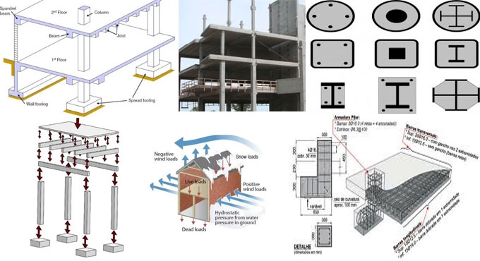
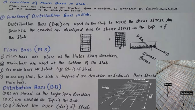
1.  The main reinforcement should be arranged at the shorter extent of the slab, as in the shorter extent slab has to undergo High bending Moment that is called sagging or positive bending moment.
2. nbsp; Main reinforcement bars have to resist and bear all the tensile stresses, bending moment (Sagging), and superimposed load (Dead load) which are formed at the shorter extent of the slabs.
3.  Main reinforcement bars are arranged in one way slab in one side (At shorter extent), but in two way slab, the bars are arranged in both ways.
4.  In Flat plate slabs the main bars are arranged in one direction at bottom of the distribution bar (in shorter extent).

5.  Main bars in the slabs should not be under 8 mm while applying (H.Y.S.D) or 10 mm for plain bars.
DISTRIBUTION BARS IN SLAB:
1.   Distribution reinforcement bar should be arranged at the longest side extent of the slab.
2.  Distribution bar are specifically created to allocate the super imposed load consistently or resist the Shrinkage stresses which are formed because of fluctuation of temperature in winter or summer.
3.   In Flat plate slab the, the distribution bars are arranged in one direction at top of main bar (in longest extent).
4.   The distribution bars should not be under 8 mm in a diameter or not in excess of 1/8 of the thickness of the R.C.C slabs.
5.   The distribution bars are arranged to retain the mesh in exact location and keep the center to center c/c, bars spacing among main bars.
VARIATION AMONG BETWEEN MAIN BARS AND DISTRIBUTION BARS:
1.  The Main bars are generally arranged at the bottom of distribution bar in slabs whereas distribution bars are arranged on the top of the main bar.
2.  The Main bars are arranged in the shorter extent of the slabs whereas distribution bars are arranged in the longer extent of the slabs.
3.  The main reinforcement is arranged to resist the bending moment, tensile stresses and superimposed load whereas distribution bars are utilized to allocate the load uniformly as well as withstand the shrinkage stress (Temperature discrepancy) or retain the mesh in exact location.
4.  Main bars in the slab should not be under 8 mm when (HYSD) or 10 mm bars are used. But, when, plain bars and the distribution bars are used, it should not be under 8 mm diameter and the bar should not be in excess of 1/8 of the thickness of the slab.
Basic variations among main bars and distribution bars

~~~~~~~~~~~~~~~~~~~~~~~~
Published By
Rajib Dey
www.constructioncost.co
~~~~~~~~~~~~~~~~~~~~~~~~

Friday, March 29, 2019

Brief overview of composite slabs and columns

Composite slabs contain reinforced concrete cast on top of profiled steel decking that functions as formwork all throughout construction and external reinforcement at the final stage.

Composite slabs:

• Comprise of profiled steel decking with an in-situ reinforced concrete topping.
• The decking (profiled steel sheeting) not only functions as permanent formwork to the concrete, but also arranges adequate shear bond with the concrete in order that when the concrete attains strength, the two materials function compositely side by side.
• Spacing should remain among 3 m and 4.5 m onto supporting beams or walls.
• When the slab is unpropped at the time of construction, the decking alone can withstand the self weight of the wet concrete and construction loads. Succeeding loads are implemented to the composite section.

• When the slab is propped, all of the loads should be countered by the composite section.
• The slabs are generally designed as simply supported members in the normal condition


Profiled steel sheeting:

• Depths vary from 45 mm to over 200 mm
• Yield strengths vary from 235 N/mm2 to minimum 460 N/mm2
• 0.8 mm and 1.5 mm thick
• The different shapes offer Interlock among steel and concrete
• Decking may also be applied to make the beams stable against lateral torsional buckling all through construction.

• Make the building stable entirely by performing as a diaphragm to transmit wind loads to the walls and columns.
• Temporary construction load generally governs the choice of decking profile.


Composite Columns: A steel-concrete composite column stands for a compression member that includes either a concrete encased hot-rolled steel section or a concrete filled tubular section of hot-rolled steel. The existence of the concrete is permitted in two ways.

• Protection from fire
• It is assumed to resist a small axial load
• Composite columns minimize the effective slenderness of the steel member that improves its resistance against axial load.


The bending stiffness of steel columns with H-or I-section is much higher in the plane of the web (‘major-axis bending’) than in a plane equivalent to the flanges (‘minor-axis bending’). The ductility performance of circular type of columns is considerably superior as compared to rectangular types. It is not necessary to arrange additional reinforcing steel for composite concrete filled tubular sections. Corrosion protection is arranged with concrete to steel sections in encased columns.

When local buckling of the steel sections may be detached, the cutback in the compression resistance of the composite column because of overall buckling should be permissible positively. The plastic compression resistance of a composite cross-section demonstrates the maximum load that can be implemented to a short composite column.

Brief overview of composite slabs and columns

Read Continue
~~~~~~~~~~~~~~~~~~~~~~~~
Published By
Rajib Dey
www.constructioncost.co
~~~~~~~~~~~~~~~~~~~~~~~~

Thursday, March 28, 2019

Advantages of Plinth beam and proper height of plinth in residential buildings

Plinth beam belongs to a RCC member. The purpose of plinth beam is to detach the superstructure and the substructure and it functions similar to a tie beam to retain columns, walls etc.

Superstructure is located over ground level that comprises of columns, beams, slabs, masonry walls etc. Substructure is located underneath the ground level that comprises of foundation.

Advantages Of Plinth Beam In House Construction :-
1. To sustain the masonry load at ground floor level
2. The objective of plinth beams is to bear the dead weight of the masonry wall (brick/block wall over it) on ground floor level


Maintain Backfilled soil: Houses are normally built up 150-300 mm over the adjoining road level(s). Plinth functions as a retaining structure for the compacted soil that is applied to fill the empty space from foundation level to top of plinth

To check/circumvent differential settlement

Foundations are exposed to differential settlement when the soil underneath is not compacted perfectly. A differential settlement leads to cracks in the masonry walls. Plinth beam belongs to an integrated structural member and it facilitates minimizing the differential settlement in the structure.

To function as a Tie-beam: Load bearing strength of columns is based on slenderness ratio. Slenderness ratio is obtained from unsupported length of column to cross sectional area of column. If the length of column is increased, the slenderness ratio is also raised to reduce the load bearing strength of the building. In order to reduce the effective length of column, tie beams are arranged and in such a situation if foundation is very deep then RCC plinth beam should be arranged. For foundations below or equivalent to 6 feet, plinth also functions as a tie beam.

Suitable Height Of Plinth:

Plinth level should remain over the adjoining road level to stop the penetration of your house in the rainy season.

Sometimes, local municipalities re-carpet the existing roads devoid of extracting old road strata at the time of repairing or building up the roads. Under such situation, nearby properties may set out under ground level and it is not recommended for practical purposes and for vastu.

To stop penetration of water or storm water into the house from outside, plinth is built up in such a manner that the top of the plinth remains adequately over road level.

If the plinth is built up too high over the road level, then the adjoining parking area level will also be raised and problems will arise.

With proper height only 3-4 stairs are necessary to get to plinth level and the bikes can be easily driven, cars can be easily parked and throughout rainfall it will safeguard property from storm and drainage water.

Because of these problems, plinth height should retain very cautiously neither too high nor too low.

The perfect plinth height should be 1.5ft to 2ft high as compared to road level.

Advantages of Plinth beam and proper height of plinth in residential buildings

Read Continue
~~~~~~~~~~~~~~~~~~~~~~~~
Published By
Rajib Dey
www.constructioncost.co
~~~~~~~~~~~~~~~~~~~~~~~~

Wednesday, March 27, 2019

Some vital tips for providing cement plaster on wall surface

Cement plastering is normally applied to provide perfect coating to the outside and inside surface of wall. Cement plaster is normally given in a single coat or double coat. Double coat plaster is suitable where thickness of plaster is retained in excess of 15 mm or when it is necessary to maintain a very fine finish. The method for double coat cement plaster involves the following 5 steps.

a. Step-1-Making the surface ready for plastering
b. Step-2-Ground work for plaster
c. Step-3-Providing first coat (or under coat or rendering coat)
d. Step-4-Providing second coat (or finishing coat or fine coat)


STEP-1 (MAKING THE SURFACE READY FOR PLASTERING)

1. Retain all the mortar joints of wall rough, in order to maintain a good bonding to retain plaster.
2. Use a wire brush to cleanse all the joints and surfaces of the wall with a wire brush, the wall surface does not contain any oil or grease etc. left on wall surface.

3. In case the surface is smooth or the plastering wall is old one, then extract the mortar joint to a depth of minimum 12 mm to provide a superior bonding to the plaster.
4. If the projection on the wall surface remains over 12 mm, then rub it out to maintain a smooth surface of wall. It will minimize the consumption of plaster.
5. For any cavities or holes on the surface, fill it with exact material beforehand.
6. Roughen the whole wall to be plastered.
7. Wash the mortar joints and whole wall to be plastered, and make it wet for minimum 6 hours prior to use cement plaster.


STEP-2 (GROUND WORK FOR PLASTER)

1. To maintain smooth thickness of plastering all through the wall surface, initially settle dots on the wall. A dot belongs to patch of plaster with size 15 mm * 15 mm and thickness of about 10 mm.
2. Initially, dots are set on the wall horizontally and then vertically at a spacing of about 2 meters coating the whole wall surface.
3. With the help of plumb-bob, examine the verticality of dots, one over the other.
4. Once the dots are set, the vertical strips of plaster alias screeds are arranged among the dots. These screeds function as the gauges for retaining smooth thickness of plastering to be used.


STEP-3 (PROVIDING FIRST COAT OR UNDER COAT OR RENDERING COAT)

1. For brick masonry the thickness of first coat plaster usually remains 12 mm and for concrete masonry this thickness differs from 9 to 15 mm.
2. The proportion of cement and sand for first coat plaster differs from 1:3 to 1:6.
3. By using a trowel, provide the first coat of plaster among the spaces developed with the screeds on the wall surface.
4. The surface should be leveled with flat wooden floats and wooden straight edges.
5. Once the leveling is finished, leave the first coat to set but not to dry and then roughen it by a scratching tool to develop a key to the second coat of plaster.


STEP-4 (PROVIDING SECOND COAT OR FINISHING COAT OR FINE COAT)

1. The thickness of second coat or finishing coat may differ from 2 to 3 mm.
2. The proportion of cement and sand for second coat plaster differs from 1:4 to 1:6.
3. Prior to provide the second coat, moist the first coat uniformly.
4. Provide the finishing coat with wooden floats to a perfect uniform surface and apply finishing touch with a steel trowel.
5. If possible, the finishing coat should be provided starting from top towards bottom and finished in one operation to remove joining marks.


As soon as the plastering work is completed, water should be sprinkled over it to keep moist for minimum 7 days to maintain strength and hardness.

Some vital tips for providing cement plaster on wall surface

Read more
~~~~~~~~~~~~~~~~~~~~~~~~
Published By
Rajib Dey
www.constructioncost.co
~~~~~~~~~~~~~~~~~~~~~~~~

Tuesday, March 26, 2019

Specifications of cement concrete in detail

Cement, fine aggregates, coarse aggregates and water are mainly used to form cement concrete. While writing detailed specifications, explain The specifications of every single component should be narrated briefly at the time of formulating detail specifications.

CEMENT: Cement belongs to the elementary and most vital component of cement concrete. The quality of cement should be fresh while utilizing it for construction work and it should satisfy the standard specifications.

FINE AGGREGATE: Sand is utilized as fine aggregate in cement concrete. Sand particles should comprise of coarse, sharp and angular edges. Size of sand particles should be maintained in such a manner that it can move through 4.75mm sieve. Sand should be clean and does not contain dust and organic matters. Sea sand should not be applied for construction work due to extreme salt contents.

Stone dust is also applied as fine aggregate in cement concrete, but prior to application, check that it adheres to specifications.

COARSE AGGREGATE: Normally, pieces of feverous rocks are applied as coarse aggregates. These stones should be solid, strong, long-lasting and clean. The shapes of aggregates should be cubic or closed to cubic shape. The shape of coarse aggregates should not be laminated and elongated. It should be clean and does not contain from any irrelevant organic matters.

The size of coarse aggregates should satisfy the approved construction work requirements. It should not move through the sieve size of 5mm and coarse aggregates should be graded. Voids should not go beyond 42%.

PROPORTIONING: Based on their fixed ratios, cement, sand and coarse aggregates should be calculated. Prepare a standard measuring box as per the volume of one cement bag. Volume of one cement bag is 1.25 cubic foot.

When, it is required to calculate the ratio of sand, bulking of sand should be taken into consideration. Choose dry sand at the time of making calculation of proportioning. Work out the moisture content in sand and include extra volume of sand. Constantly work out moisture content throughout construction work and include extra volume of sand based on the amount of moisture. It is suggested not to compact coarse aggregates at the time of proportioning.

CONCRETE MIXING: Mixing machine is suitable for large scale construction works whereas hand mixing is chosen since it is cost-effective for smaller concrete works.

CONCRETE CONSISTENCY: Concrete consistency is based on water to cement ratio. Surplus amount of water reduces the strength of concrete and also concrete constituents can be easily detached. The quantity of water given below should be applied against 50kg cement bag.

Concrete Ratio - Amount of Water
1:3:6 - 34 liters
1:2:4 - 30 liters
1:2:3 - 27 liters
1:1:2 - 25 liters


If vibrator is utilized for concrete compaction, then the amount of water should be reduced as per suggestion of engineer in charge.

 Specifications of cement concrete in detail
Read more
~~~~~~~~~~~~~~~~~~~~~~~~
Published By
Rajib Dey
www.constructioncost.co
~~~~~~~~~~~~~~~~~~~~~~~~

Monday, March 25, 2019

Some useful tips to examine concrete formwork in job site

The finalized inspection of concrete formwork should be examined prior to set the reinforcement bars in exact location. By implementing perfect form work, honey combing, blow holes, grout less or discoloration of concrete can be circumvented and consequently the finished surface of concrete becomes superior.

Prior to commencement of concreting work, shuttering surface should be fully cleansed and does not contain any defect/deposits in order to provide rightly straight smooth concrete surface. Shuttering surface does not contain any damage and unnecessary roughness to its surface.

While building concrete form work, the following should be examined properly.

1. Any member to be retained in position once the general dismantling is completed, should be labeled perfectly.
2. The applicable materials should be thoroughly examined in order that no incorrect items/rejects are utilized.
3. When excavations exist nearby reformatory and strengthening action should be undertaken to impact the safety of form work.
4. The quality of bearing soil should be strong and it should be arranged properly and the sole plates should bear well on the ground. Sole plates should be perfectly placed on their bearing pads or sleepers. The bearing plates of steel props should not be deformed. There should be adequate bearing areas for the steel sections on the bearing members.

5. There should be proper safety provisions to get rid of impact of traffic, scour caused by water and accidental impacts.
6. To maintain proper strength and durability of form work at intermediate stage, bracing, struts and ties should be provided together with the advancement of form work. Avoid ‘Tilting and overturning of steel sections.
7. While applying customizable steel props, no damage and evident bents should be observed; steel pins should be arranged, restricted latterly near each end.
8. Screw adjustments of adaptable props should not be over extended.

9. When settlement/elastic shortening of props happens, double wedges should be arranged for correction of the form to the desired position. Wedges are applied only at bottom end of single prop and should not be very steep and one of the pair should be secured/clamped down after correction to avoid their shifting.
10. No member should be eccentric over vertical member.
11. There should sufficient number of bolts and nuts and cantilever supports.
12. Props shall remain directly under one another in multistage construction.
13. Guy ropes or stays should be perfectly tensioned.
14. Provision should be arranged for movement and operation of vibrator and other plant and equipment.
15. Required camber should be arranged over long spans.
16. Supports shall be sufficient and in plumb.


Some useful tips to examine concrete formwork in job site

Read more
~~~~~~~~~~~~~~~~~~~~~~~~
Published By
Rajib Dey
www.constructioncost.co
~~~~~~~~~~~~~~~~~~~~~~~~

Wednesday, March 20, 2019

Some useful guidelines to develop a building foundation

While building up a foundation for a building, adequate knowledge is required with some particular steps to make sure that the footings will retain the weight of the building through rest of time.

The purpose of building foundations is to bear the load of the structure as well as disperse the load to the soil in greater cross sectional area. The foundation should have the capacity to resist the load of the structure along with the live loads and environmental factors.

A safety factor is arranged for safety all through the foundation design. The foundation is built up on the basis of the design. Given below, some vital steps, which should be abided by, at the time of constructing & designing building foundation.

1: Survey and Stake Out Footprint - A professional surveyor should execute this step. The surveyor will settle on the exact distances from the property lines. It makes sure that the building will set out perfectly and abide by the code. The corners of the building will be marked with surveyor’s stakes.

Then the surveyor will arrange offset stakes about two feet out from the surveyor’s stakes. The digging for the foundation will start by applying the offset stakes as the guides. It accomodates extra room so the work can be performed on the exterior foundation walls.

2: Excavation - A structural engineer is required to define the depth of the excavation. All surface soils should be eliminated to uncover the soil that is properly compressed to carry the weight of the building.

The depth will differ for each building. The top of the footing should remain underneath the frost line since it resists the concrete from cracking when the freeze-thaw cycle happens in the soil that encircles the building.

3: Footings - A footing stands for a poured concrete pathway that is applied to expand the weight of the building from the foundation walls to the soil. They are larger as compared to the foundation walls that they are supporting and create the perimeter of the building. In some cases, there exist extra footings which are provided inside the perimeter to provide support to the load-bearing walls.

4: Sub Slab - Normally, plumbing lines are arranged from the street to the building’s basement by passing over or even below the footing. It occurs for the buildings which contain their own separate sewage facility or drain field. A poured concrete slab is used to cover these lines.

5: Foundation Drainage System - Subsurface water is preserved and pushed away from the foundation to get rid of pooling water or flooding. The foundation drainage tile is constructed with an incessant run of punched drainage pipes which are implanted in gravel along the foundation of the building. In some areas, a sump pump may also be needed to facilitate accumulating the subsurface water.

To gather knowledge on other steps, go through the following link civilengineersforum.com

Some useful guidelines to develop a building foundation

~~~~~~~~~~~~~~~~~~~~~~~~
Published By
Rajib Dey
www.constructioncost.co
~~~~~~~~~~~~~~~~~~~~~~~~

Tuesday, March 19, 2019

How to measure minimum bar spacing for Bundle Bars in Cast-in Place Concrete as per AASHTO provisions

Minimum Bar Spacing: As per AASHTO LRFD, section 5.10, the minimum bar spacing for bundled bars should be measured on the basis of the acquired diameter rather than computing from individual diameters.

As for instance, if there are 2 nos. 32 mm dia bars, the similar diameter in accordance with 2×32 is 45mm. Therefore, 45 should be employed to utilize the following clauses from AASHTO.

For 2×32 dia bars, clear spacing should be provided as ~68mm for Cast-in Place concrete and 60mm for precast concrete.

Refer following Clauses from AASHTO LRFD 5th Edition 2010


5.10.3.1.1—Cast-in-Place Concrete
For cast-in-place concrete, the clear distance among parallel bars in a layer should not be under :
5 times the minimal diameter of the bars,
5 times the maximum size of the coarse aggregate, or 1.5 in.
5.10.3.1.2—Precast Concrete
For precast concrete fabricated under plant control conditions, the clear distance among parallel bars in a layer should not be under :
The minimal diameter of the bars,
33 times the maximum size of the coarse aggregate, or 1.0 in.
5.10.3.1.5—Bundled Bars
The number of parallel reinforcing bars bundled in contact to function as a unit should not go beyond four in any one bundle, apart from flexural members, the number of bars greater than No. 11 should not go beyond two in any one bundle.
Bundled bars should be attached within stirrups or ties. Individual bars in a bundle, cut off inside the extent of a member, should be abandoned at several points with minimum a 40-bar diameter stagger. Where spacing limitations are dependent on bar size, a unit of bundled bars should be considered as a single bar of a diameter taken from the corresponding total area.
How to measure minimum bar spacing for Bundle Bars in Cast-in Place Concrete as per AASHTO provisions
~~~~~~~~~~~~~~~~~~~~~~~~~~
Published By
Rajib Dey
www.constructioncost.co
~~~~~~~~~~~~~~~~~~~~~~~~~~

Monday, March 18, 2019

Common methods for concrete construction

In this civil engineering article, you will get detail information on the most common methods for developing a concrete structure.

Designing the concrete mix: The most vital part in the method is to find out the components that will form the concrete and their ratios. Several types of variables should be taken into consideration at the time of designing which range from cement type, aggregate size and type, amount of water, and mineral and chemical admixtures.

A good mix design can also lead to improper or substandard quality concrete when it is accomplished inappropriately. Based on the type of project, it is decided who will take responsibility for designing the mix. For large, publicly funded projects, a licensed civil engineer should be liable for the final design.

For residential projects like foundations and driveways it is the private contractor, who will prepare the mix design. For do-it-yourself projects it is of course the homeowner who should take responsibility to design his own mix.

To produce an exact mix design, initially, detect the properties that the fresh and solidified concrete should have and then move backwards to opt for the most inexpensive mix design that provides these properties.

Here, focus should be given on the following factors :

Supported Loads: Concrete is formed with different types of strengths, so this is considered as the gateway of the mix design. As the cost of concrete scales rather narrowly with its strength, one does not like to make the concrete stronger than it should have been.

However, if the application provides support to considerably small loads, it is generally not a good idea to indicate weak concrete since weak concrete does not have good stability. For low load applications the quality of the concrete is settled with other factors like resistance to freezing or wear resistance.

Workability: The necessary workability is mainly based on how the concrete will be arranged. Concrete can be poured, pumped, and even sprayed into place, and it will impact the desired workability. Various other factors like the shape of the molds, the rebar spacing, and the accessible equipment at the site for solidifying the fresh concrete once it is placed should also be taken into consideration.

Workability is generally settled with the slump, the tendency for the fresh concrete is to expand under its own weight when it is arranged onto a flat surface.

Environmental conditions: When the concrete is uncovered to severe conditions, then this may perfectly ascertain the required concrete quality in spite of the applied loads. In cold-weather locations the concrete should have the strong resistance capacity against freezing. Besides, it must have the ability to resist the corrosive effects of salt. Underground applications should have the capability to withstand the penetration of moisture and aggressive species from the soil. For almost any type of conditions or mode of attack, the most effective way for defense is to retain the w/c low.

Surface wear: For some applications the physical loads can erode the concrete rather than breaking it. For roads, parking garages, driveways, and industrial floors, the longevity of the structure depends on the hardness and wear resistance of the top layer of concrete.

Common methods for concrete construction

Read more
~~~~~~~~~~~~~~~~~~~~~~~~
Published By
Rajib Dey
www.constructioncost.co
~~~~~~~~~~~~~~~~~~~~~~~~

Saturday, March 16, 2019

Smart Concrete – The newest upcoming technology to detects cracks in concrete earlier

The concrete is extensively used as a composite material for several types of structures but the concrete lacks the strength to resist tension and as a result it can be cracked easily. Therefore, the concrete should be examined thoroughly for cracks and proper and timely repairs should be undertaken so that the quality of the concrete is not deteriorated.

In this way, the safety and stability of different structures are maintained. Another process for determining cracks is to attach sensors to the structure but the installation charge is costly.

Smart concrete technology is the newest concept for examining the health of reinforced concrete structures. The type of concrete is reinforced with carbon fiber comprising of 0.2% to 0.5% of the volume. It can determine the pressure on the concrete structure well in advance. Smart concrete technology has witnessed broad laboratory testing, but has not launched yet.

It becomes functional with the addition of a small amount of short carbon fiber to the concrete with a traditional concrete mixer to change the electrical resistance of the concrete with regards to tension or pressure.

Accordingly, contact among the fiber and the cement matrix is impacted while the concrete is deformed or depressed, thus affecting the electrical resistivity of the concrete volume. Tension is then exposed by calculating the level of electrical resistance.

Smart concrete has the ability to recognize very small structural weaknesses before it gets significant and therefore becomes applicable in checking the internal conditions of the structure, especially after an earthquake.

Besides, identifying small cracks, smart concrete also allows stopping the development of cracks in traditional concrete and reinforce it to make it stronger. Besides, it takes a lot of strength to bend smart concrete, and consume more energy before breaking.

Smart concrete can also be applied in the construction of highways since they can easily find out the weight of the vehicle. Roads constructed with smart concrete can detect the position, weight, and speed of the vehicle.

Smart Concrete – The newest upcoming technology to detects cracks in concrete earlier

Read more
~~~~~~~~~~~~~~~~~~~~~~~~
Published By
Rajib Dey
www.constructioncost.co
~~~~~~~~~~~~~~~~~~~~~~~~

Friday, March 15, 2019

Properties and benefits of self compacting concrete

Self-consolidating alias self-compacting concrete is an extremely flowable type of concrete that does not need vibration for setting and compaction.

It is compressed into each corner of a formwork perfectly with its self weight exclusive of any external vibrators. It is a fully engineered concrete with greater fluidity.

Self compacting concrete retains all the strength and characteristics of concrete satisfying desired performance requirements.

In some specific conditions the inclusion of superplasticizers and viscosity modifier with the mix, the bleeding and segregation is significantly reduced. The strength is decreased for the concrete that segregates and as a result honeycombed areas are produced next to the formwork. A properly designed SCC mix does not segregate and it retains extreme deformability and outstanding stability characteristics.

Advantages of SCC:

a. Curtailment in site manpower
b. Problems due to vibrators are reduced
c. Easy to set
d. Rapid construction
e. Superior surface finish
f. The strength is enhanced because of superior compaction and uniformity of concrete.


Characteristics Of Self-Compacting Concrete

Self-compacting concrete has strong resistance capacity against segregation with mineral fillers or fines as well as special admixtures. It should have the flexibility to be flown and filled special forms under its own weight, it should be flowable enough to move across highly reinforced areas, and should have the capability to get rid of aggregate segregation. This type of concrete should fulfill special project requirements regarding placement and flow.

Self-compacting concrete having a similar water cement or cement binder ratio will generally contain a marginally higher strength with regard to conventional vibrated concrete, without proper vibration, a superior interface among the aggregate and hardened paste will be created.

The concrete mix of SCC should be set at a considerably higher velocity as compared to traditional concrete. Self-compacting concrete should be set at heights greater than 5 meters devoid of aggregate segregation. It can also be applied in areas with normal and congested reinforcement, with aggregates as large as 2 inches.

Self-Compacting Concrete Uses - Self-compacting concrete is mostly found in bridges and even on pre-cast sections.

a. Conclusion
b. Self compacting concrete can save time, cost as well as improve strength.
c. SSC can be efficiently transformed into congested reinforced areas like columns, drilled shafts.


To get more details, go through the following link csengineermag.com

Properties and benefits of self compacting concrete

~~~~~~~~~~~~~~~~~~~~~~~~
Published By
Rajib Dey
www.constructioncost.co
~~~~~~~~~~~~~~~~~~~~~~~~

Thursday, March 14, 2019

Some best formwork methods

Formwork means the temporary or permanent molds which are applied to retain wet concrete unless it gets cured. It is a vital component in concrete construction as without formwork the schedule, labor requirements, quality and total cost of a project are significantly impacted.

In due course of time, formwork molds have changed from conventional job-built timber to pre-engineered systems comprising of a combination of steel, aluminum, manufactured timber, plywood and plastics.

These improvements in formwork molds make the jobsite production & safety better, with fewer labor, whereas creating a superior finished product.

Walls—Now-a-days, steel-framed, wood-faced panels, which need consumable ties at 2-feet-on-center and one connection per square foot, are extensively used for handset wall forming. These are substituted with larger, two-person handset systems which need less labor and get rid of consumable purchases due to reusable taper ties.

In recent times, clamp connection forms having wood or plastic form faces that offer tremendous labor savings in assembly, are utilized. Assembly and reconfiguration of these standard systems to satisfy changeable structure dimension takes place instantly, and also offers a consistent concrete finish.

Slabs—The application of fixed or tailor-made wood posts, stringers and joists is still considered as the most common method of shoring of slabs. This method delivers from generation to generation and considerable labor is required for that. Since, the posts are arranged as close as 2-feet-on-center, construction sites turn out to be very congested.

A new construction method that highlights engineered lumber and metal posts raise the post spacing up to 5 feet by 10 feet and suggests components which are systematic and can be reprocessed. This increases spacing and facilitates less material on site to develop the same slab area. Less material leads to lowered handling requirements, less labor to arrange and strip the formwork, fewer transport costs, and an improve overall job site productivity.

The existing method for gang-forming slabs applied trusses or structural decks based on significant amount of time for assembly and disassembly. Besides, this method requires a huge amount of crane time, thus accelerating the time for resetting a suitable operating method. The customer should also purchase the plywood facing and often restore it several times on the same project.

Gang-forming slabs are commonly found on the structures with height in excess of 15 stories with the purpose of reducing cost. To provide a greater solution to these types of systems, smaller tables are arranged to the job site fully assembled with plywood especially for mid-rise buildings where gang-forming was not inexpensive earlier.

The formwork-lifting elevators affixed to the exterior of a building that facilitates all formwork to be cycled from floor to floor devoid of requiring a crane to decrease job site crane time & formwork labor requirements. These table-lifting systems are applied along with the smaller table method and also allow for other construction material like handset shoring, vertical formwork and reshores from below to cycle from floor to floor with a crane.

How to choose the exact formwork

Structural engineers should be aware that concrete contractors carry out a detailed analysis of available formwork solutions to arrange the best system for the construction project since conditions differ for each individual project, there is no simple formula for the selection of the proper formwork supplier or system.

Generally, formwork should include 40- to 60-percent of the total cost of a building’s structural concrete frame. For concrete walls, the cost remains 50- to 60-percent range. These percentages involve the cost of material and labor, with the largest cost being for labor. It is vital to analyze the labor costs comprehensively since it is the higher expenditure and is that amount is decreased, it offers superior effect on the bottom line.

To provide the most effective solution for a project, a contractor will calculate different forming systems. Since the scarcity of available and capable labor continues, it has become even more important to opt for proper forming system. So, there are two options for a contractor - a low-priced forming material that is labor-intensive or a forming system that is costly but offer high productivity.

To get more details, go through the following link csengineermag.com

Some best formwork methods

~~~~~~~~~~~~~~~~~~~~~~~~
Published By
Rajib Dey
www.constructioncost.co
~~~~~~~~~~~~~~~~~~~~~~~~

Wednesday, March 13, 2019

Clear Cover and Nominal Cover used for RCC Structure

The concept of Clear cover and nominal cover is seen in the Reinforced concrete structures.

Reinforced concrete structures have been main structural materials for over a century and still the most popular material for public structures all over the world. The concrete structure is durable enough to keep its shape for a long time.

The reinforced concrete structure refers to the members like beams, boards, columns, and roof trusses etc. which are consisted of concrete and steel bars.

In these structures, the steel bars are covered by concrete but their mechanical properties will still lose due to the fire to destroy the whole structure.

In this design of reinforced concrete structures, the provided reinforced is inserted in the concrete upto a particular distance from the face of the member as there are some reasons.

The reasons are discussed below:

• It will provide protection to reinforcement from erosion
• It will also provide fire resilience to reinforcement.
​• It will also supply sufficient embedded depth so that reinforcement grows the requisite stress.


This distance is measured in various ways and known by different names like:

• Clear cover: This is the difference from the face of the member to the outermost face of the reinforcement including shear or torsion Stirrups or links.
• Nominal cover: This cover is like the same as Clear Cover although it has different name; actually the name is a term that is used by the code. It is the distance measured from the face of the member to the outermost face of the reinforcement including Stirrups or links.


To get information on other clear cover and nominal cover, go through this useful civil engineering video tutorial.


Video Source: CE&T-Civil Engg & Technology

~~~~~~~~~~~~~~~~~~~~~~~~
Published By
Rajib Dey
www.constructioncost.co
~~~~~~~~~~~~~~~~~~~~~~~~