adsense analytic

Saturday, September 29, 2018

Some common types of columns (14 types) in building construction

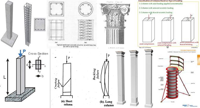
Various sections of structures are supported with different types of columns. Column stands for a vertical structural member that bears loads primarily in compression.

It generally transmits loads from a ceiling, floor slab, roof slab, or from a beam, to a floor or foundations.

Usually, columns also bear bending moments about one or both of the cross-section axes. Given below, the detail lists of columns mostly found in building construction :-

Columns are categorized on the basis of the following factors :

1. Types of Reinforcement
2. Types of Loading
3. Slenderness Ratio
4. Shape
5. Construction Material


Depending on types of reinforcement:

1. TIED COLUMN: Reinforced concrete is the prime material to build up this type of column. Longitudinal reinforcement is enclosed inside narrowly placed tie reinforcement. It is considered that 95% of all columns in buildings are tied.

2. SPIRAL COLUMN: Reinforced concrete is used to construct spiral column. In this type of column, longitudinal bars are enclosed inside narrowly placed and constantly distressed spiral reinforcement.

Spiral reinforcement offers lateral restrains (Poisson’s effect) and defers axial load failure (ductile).

3. COMPOSITE COLUMN: A composite column is formed if the longitudinal reinforcement is in the form of structural steel section or pipe including or excluding of longitudinal bars.

This type of column contains greater strength containing fairly small cross section, apart from showing good fire performance.

4. AXIALLY LOADED COLUMN: If vertical axial loads operate on the center of gravity of the cross-section of the column, then it is called as axially loaded column.

Axially loaded column is seldom found in construction as synchronizing vertical loads on the center of gravity of column cross section is not possible.

Instance of this type of column is Interior column of multi-storey buildings having symmetrical loads from floor slabs from all sides.

5. COLUMN WITH UNIAXIAL ECCENTRIC LOADING: If vertical loads do not synchronize with center of gravity of column cross section, but rather function eccentrically either on X or Y axis of the column cross section, then it is known as uniaxially eccentric loading column.

Column with uniaxial loading are usually adopted in the case of columns firmly attached with beam from one side only like edge columns.

6. COLUMN WITH BIAXIAL ECCENTRIC LOADING: When vertical on the column is not synchronized with center of gravity of column cross section and does not operate on either axis (X and Y axis), then the column is known as biaxially eccentric loaded column.

Columns with biaxial loading are normally found in corner columns having beams firmly attached with right angles at the top of columns.

To learn how column is categorized on the basis of slender ratio and construction material, go through the following link allengineeringideas.blogspot.com

Some common types of columns (14 types) in building construction

~~~~~~~~~~~~~~~~~~~~~~~~
Published By
Rajib Dey
www.constructioncost.co
~~~~~~~~~~~~~~~~~~~~~~~~

Friday, September 28, 2018

Fineness test of Cement and its Significance

Fineness of Cement is tested by sieving cement on standard sieve. The purpose of this test is to find out the proportion of cement of which the cement particle sizes are in excess of 90 micron.

Importance of the fineness test of cement:-

It is known that cement hydrates with the existence of water. If cement is blended with the water, a thin layer is produced around the particle. This layer gradually becomes larger and compels the cement particles to detach. Because of this, hydration process becomes slow. So, the smaller particle will function rapidly as compared to the bigger particle. A particle containing dia 1µm will react fully in one day, while the particle containing dia 10µm takes about one month. Therefore, the allocation of the particle size is very important in achieving the final strength of cement in acceptable time.

If lots of smaller particles exist in cement, there will not be sufficient time for mixing, handling and placing because of quick setting. In order to raise the setting time of cement, cement should be grounded in various range of particle sizes.

The following proportions should be retained in Cement: About 10% of the cement of fine particles is smaller than 2 µm, 10% of wt of cement is formed with particles greater than 50 µm, and only a few wt% is particles greater than 90 µm.

Fineness test of Cement:-

According to IS: 4031 (Part 1) – 1996. The good quality cement should contain under 10% of wt of cement particles greater than 90 µm. (micron).

The following tools are applied to find out the number of cement particles greater than 90 µm. or Fineness test of cement.

100g of cement (test sample), Weighing balance that can weight with an accurateness of 1mg, Standard Sieve of size 90 µm, Sieve pan with lid, Sieve Shaking Machine(optional).

Method for determining fineness test of cement:

1. Choose a sample of cement and wipe it with your hands. You should feel no lumps in the cement.
2. Now choose 100g of cement and label it as W1.
3. Pour 100g of cement in 90 µm sieve and seal it with the lid.
4. Now arrange the sieve in Sieve shaking machine. It is also possible to shake the sieve with your hands by stirring the sieve in planetary and linear movements for 15 minutes.

5. Now, take weight of the leftovers preserved on the 90 µm sieve as W2.
6. Then, workout the percentage of Wt of cement-retained on sieve.
7. Reiterate the above experiment with three diverse samples of cement and average the values to obtain perfect result.


The fineness of Cement Formula:-

A good cement should maintain 10% wt of cement when it is sieved with the 90µm sieve.


Fineness test of Cement and its Significance

Read more

~~~~~~~~~~~~~~~~~~~~~~~~
Published By
Rajib Dey
www.constructioncost.co
~~~~~~~~~~~~~~~~~~~~~~~~

Thursday, September 27, 2018

Various applications of Concrete Structure Casting Remnants

The concrete applied in construction is frequently wasted in the process because of several errors in casting. The waste of ready-mix concrete is influenced by various factors like miscalculations / calculations in the jobsite, defective equipment, harmful weather, as well as inappropriate application methods resulting in wasting of materials.

Given below, some useful suggestions for utilizing the leftover concrete casting structures which can reduce the expenses of a project.

1. Applied as a practical column or lintel beam in precast.

In several enormous projects, precast methods are utilized for the wall installation work of practical columns or lintel beams. Normally, instant concrete with K-225 or K-250 is utilized. It is beneficial to utilize the structural casting residual concrete to minimize concrete waste and instant concrete purchases.

2. Applied as a cansteen

Cansteen belongs to the edge of the pedestrian, sidewalk, separator, edge of the road, park path, boulevard, and so on. It is utilized as a roadside amplifier. Normally, cansteen is measured in BQ to order the finished product. It will be better to install it in precast. Structural casting residual concrete is utilized as cansteen to reduce the budget.

3. Applied as a Car Stopper

Car stoppers belong to embankments for providing protection to the parking area to stop the moving cars. Normally, various types of materials like iron pipes, concrete and rubber are usually applied as car stoppers.

4. Applied as Paving Block

Paving blocks are mostly utilized as outdoor parking areas, jogging tracks, parks, sidewalks, home yards and pedestrians. These blocks are made precast with leftover concrete casting materials. Thus, the project costs will be curtailed significantly.

Various applications of Concrete Structure Casting Remnants

Read more

~~~~~~~~~~~~~~~~~~~~~~~~
Published By
Rajib Dey
www.constructioncost.co
~~~~~~~~~~~~~~~~~~~~~~~~

Wednesday, September 26, 2018

Some useful guidelines to substitute the spalling bricks

Freezing and thawing water in brick leads to flaking and spalling and due to these the bricks are damaged severely.

In this construction article, you will get some useful tips for recognizing spalling on bricks. Besides, you will learn how to take proper measures so that the water can’t enter into the brick walls. Otherwise, it will be necessary to substitute the damaged bricks.

How to substitute the damaged bricks

The brick retaining wall under a wood fence may be broken down. The flaking surface is a good instance of “spalling,” a type of failure resulting from moisture and the freeze/thaw cycle. Water from rainfall, melting snow or even wet soil soak the brick to some extent, and freeze inside the brick while the temperature is decreased.

The small development of freezing water will rupture the brick. If freezing and thawing occur in continuous basis, the fractures are expanded unless the brick is perfectly decomposed.

To get rid of these issues, bricks utilized on the outside should normally become tougher and solid (less moisture absorption). A softer brick in the wall that is mixed in the load may collapse. If massive failure occurs, there is serious water intrusion issue.

The outside walls should be detailed cautiously to discharge water, specifically when they’re inherent section of a retaining wall. There should be a coping or cap on the wall to discharge the rain water.

It comprises of metal flashing, concrete or special bricks which are angled to keep water far from the top of the wall. The cap exists there for one time, but it may be eliminated or tired. Besides, the wood fence over perhaps catches and directs even more water down onto the wall.

While going to reconstruct your brick wall, ensure it’s designed to reduce water penetration. Aside from a cap on the top, it should contain good draining fill (gravel) along the backside and weep holes along the bottom to lessen water pressure when the soil gets soaked.

Damp-proofing the backside of the wall will also facilitate the water to be discharged properly. There should be good drainage system around the base to resist penetration of water from below.

Necessary Tools for this Spalling Project

Given below, the detail lists of tools :-

Circular saw, Cold chisel, Dust mask, Extension cord, Hammer, Hearing protection, Level, Safety glasses, Sledgehammer, Spade, Tape measure, Trowel, Utility knife, Wheelbarrow.

A masonry blade is also necessary to cut the brick with circular saw.

Essential Materials for this Spalling Project

Brick, Drain tile, Gravel, Landscape fabric, Mortar.

Some useful guidelines to substitute the spalling bricks

~~~~~~~~~~~~~~~~~~~~~~~~
Published By
Rajib Dey
www.constructioncost.co
~~~~~~~~~~~~~~~~~~~~~~~~

Tuesday, September 25, 2018

CSiBridge 20.2.0 is recently launched to make the bridge modeling process smarter

Given below, the detail and improved features of CSiBridge.

Bridge Modeler: The rapid bridge template is extended to help in explaining a more complete model along with substructure, superstructure, loading, and design criteria.

Bridge deck section superstructure loads offer the ability to effortlessly model barrier, median, sidewalk, haunch, construction, and wearing surface loads.

User specified diaphragm depths can now be stipulated for precast I-girder and concrete tee bridges Modeling.

Automated pre-stress tendon creation on the basis of tendon layouts described in precast I-girder frame section properties Analysis.

Dynamic collapse analysis facilitates an object to be eliminated throughout a nonlinear direction integration time history analysis Bridge Design.

Bridge superstructure design is included with reference to the AASHTO LRFD 2017 8th Edition code.

Load rating of steel U-girder composite bridges is included with reference to the AASHTO Manual for Bridge Evaluation 2nd Edition.

Load rating of steel U-girder composite bridges is included with reference to the CAN/CSA-S6-14 code.

To download the software, click on the following link www.civilax.com/csibridge-2018-v20-2-0

CSiBridge 20.2.0 is recently launched to make the bridge modeling process smarter


~~~~~~~~~~~~~~~~~~~~~~~~
Published By
Rajib Dey
www.constructioncost.co
~~~~~~~~~~~~~~~~~~~~~~~~

Monday, September 24, 2018

Some best software for structural analysis and design

Now-a-days, lots of software emerge in the market to design, analyze and develop large projects rapidly. The 3D integrated structural design and analysis software become very popular amid structural designers.

These simplified structural analysis and design software are applied to increase productivity. These software facilitate the structural modeling and load analyzing more consistent and well organized, as a result the time and effort are curtailed significantly for finite element analysis.


These design/analysis software comprise of some exclusive features which range from analysis of diversified profile of structural components, modeling structure of different materials, outputting analysis and graphical files, and examining geometrical errors. Given below, the detail lists of five best software for Civil and Structural Engineering.

Analysis & Design:

STAAD Pro: It belongs to a structural design and analysis tool that is treated as the best structural analysis software for worldwide structural engineers. It is very user-friendly and contains an extensive range of essential tools essential for executing an analytical process on several structures.

STAAD Pro is further integrated with a series of other Bentley products. The models produced with STAAD Pro can be imported to OpenSTAAD in order to make the models transmittable to other third-party tools.

SAFE: This software is frequently applied in designing foundation slab systems and concrete floors. SAFE is a comprehensive package that integrated all the features of engineering design process ranging from generating layout to detail drawing production in a single, intuitive environment.

It facilitates highly advanced local appraisal of foundation systems inside greater structures and imports files from CAD, ETABS, and SAP2000.

Given below, some of the other significant advantages of the software :

1. Extensive lists of templates to swiftly set up a model
2. Post-tensioning
3. Support conditions and loadings


RISA: It is another leading 3D analysis and design tool for developing general structures like buildings, bridges, arenas, industrial structures, crane rails, and more.

It is rapid, productive and reliable. It contains an insightful interface that combines with several other products like RISAFloor and RISA Foundation. It comprises of the newest steel, cold-formed steel, concrete, aluminum, masonry and timber design codes. It consecutively offers the tools which are required to manage the multi-material projects without any difficulty.

3D Environment:

Navisworks: The design, engineering and construction management professionals use this software to get brief understanding of the project and improve the productivity and quality. It facilitates the users to open, combine, review and distribute Detailed 3D Design models in different file formats. It allows the users to import all file formats and integrate all the files to generate a model.

Some best software for structural analysis and design


~~~~~~~~~~~~~~~~~~~~~~~~
Published By
Rajib Dey
www.constructioncost.co
~~~~~~~~~~~~~~~~~~~~~~~~

Friday, September 21, 2018

Some vital tips to select the exact frame for your steel building

Before starting the design of any steel building, the type of frame perfectly suitable for the building should be chosen preliminary.

Steel buildings have good versatility and flexibility in frame design and application because of extreme strength to weight ratio of steel.

The strength and stability of steel helps in making a wide array of frame designs and styles to meet almost any requirement.

Given below, different types of frames for your steel building:

I-BEAM AND TAPERED BEAM: I-beam style frames are mostly recognized.

a. The frame is constructed with in-built plate sections connected together or from hot-rolled beams.
b. The "I" in I-beam originates from the cross-section of the beam that is shaped just like the letter that recognizes it.
c. The I-beam design is instrumental in building high-rise structures with highest strength and lowest material.


I-beam structures are also described as straight column buildings where the columns contain identical width across their length. The tapered beam belongs to a straight column rigid frame that expands the interior space.

The tapered beam is suitable for smaller buildings where clear spans are needed. A tapered beam building is easily divided into interior bays and is an optimal design for employing small crane support systems.

Tapered beam is also known as tapered column. The thicker end of the column is connected with the thicker end of the crossbeam at the joint among wall and roof, arranging an exceptionally strong joint at the eave. The narrow ends intersect at the roof line or expand to the ground.

The lower interior space is increased whereas the column is sufficiently strong to provide support for cranes and other equipment for passing items within.

OPEN WEB DESIGN: Open webs are also called as trusses. The web is developed with a top and bottom chord attached with diagonal angles. Open web design is a cost effective and perfect choice for clear spans of 250 feet and greater.

However, it is quite complicated to fabricate as compared to other designs.

Open web design facilitates you to integrate HVAC, wiring, and sprinkler systems directly into the truss framework, leaving the interior open and column-free.

To get more details, go through the following link www.whirlwindsteel.com

Some vital tips to select the exact frame for your steel building

~~~~~~~~~~~~~~~~~~~~~~~~
Published By
Rajib Dey
www.constructioncost.co
~~~~~~~~~~~~~~~~~~~~~~~~

Thursday, September 20, 2018

Variations among Load bearing and framed structures

Superstructure is the section that situates over the ground. It comprises of walls, columns, beams, floors, roofs, doors, windows, lintels, staircases.

Types of super structures on the basis of load transmission

The super structures are categorized as follow :-

a. Load bearing structures
b. Framed structures


Load bearing structures:

Under this type of structure, the load on the structure is delivered in vertical direction through walls and then the wall transmits these loads and the self weight. These types of constructions are mostly found in residential buildings where the dimension of rooms is fewer. The residential buildings up to ground + 2 floors is constructed inexpensively with such structures.

Framed structures:

Under this type of structures, a frame work of columns and floors are constructed initially. Then the walls are erected to divide the living area.

The walls are dependent on self weight only. These types of structures are suitable when there are lots of stories in a building as well as when bigger areas should be covered free from walls.

Variations among load bearing and framed structures

Load bearing structure:

1. Construction cost is minimum
2. Best fit up to three stories
3. Walls are thicker and consequently floor area is curtailed.

4. Construction process is slow.
5. Once the construction is completed, it becomes difficult to modify the position of walls.


Frame structure:

1. The construction cost is higher
2. Ideal for different number of stories
3. Walls are thinner and as a result, more floor area can be utilized.
4. Rapid construction speed

5. If required, the location of wall may be modified.
6. Resistance to earthquake forces is good


Variations among Load bearing and framed structures

Read more

~~~~~~~~~~~~~~~~~~~~~~~~
Published By
Rajib Dey
www.constructioncost.co
~~~~~~~~~~~~~~~~~~~~~~~~

Wednesday, September 19, 2018

Types of construction beams and their uses

Beams are the horizontal member of a structure as well as weight-bearing supports that carry transverse loads. Beams transmit all the loads along with its own weight to the columns or walls.

The posts and columns, belong to the vertical companions of the beam and provide strong support to maintain the structural integration for all types of buildings.

The beams are present in walls, floors, ceilings, roofs, decks and garages of any building. Given below, the basic characteristics of a beam.

I-Beams: I-beams are generally used in big commercial building projects, but they also construct houses, particularly interior walls.

The I-beams are generally arranged on top of foundation or basement walls to give support to the upper level of the house. They're frequently utilized in garages where they are utilized as tracks or rails for the motorized wheeled trolleys which open and close garage doors.

Flitch Beams: Steel fabrication companies produce flitch beams by coupling lengths of wood and metal jointly. The wooden section can be fixed to other structures, whereas the metal part offers extra strength.

The outcome is lighter than a steel beam but can carry adequate weight as compared to a wooden one. Flitch beams are specifically usable throughout renovations work where a load-bearing wall is eliminated.

Box Beams: Box beams are also called as box girders. Box beams are lengths of wood or steel which are attached at right angles to make something similar to a long, hollow box. Box beams are conventionally built up with wood, and three-sided box beams are commonly connected with ceilings to provide visual interest as well as support. Four-sided box beams are commonly used.

Hip Beams: Hipped roofs contain four sloping sides. The "hip" is where various roof sections intersect. The hip beams or rafters are necessary for these types of roofs.

Every hip beam supports various smaller pairs of beams that stretch from it. Wooden beams are conventional, but steel versions are gaining popularity since homeowners transform unfinished or obsolete attics and lofts into modern living spaces.

Cantilever Beams: The cantilever beams are useful for projecting house components like bay windows, balconies, roofs and canopies. As attached structures support them at just one end, cantilever beams appear to protrude from buildings.

A cantilever beam disperses its weight either at or along the unsupported segment of the beam.

Bond Beams: Bond beams are set inside masonry like stone, clay, brick or cement walls.

To get more information, go through the following link hunker.com

Types of construction beams and their uses

~~~~~~~~~~~~~~~~~~~~~~~~
Published By
Rajib Dey
www.constructioncost.co
~~~~~~~~~~~~~~~~~~~~~~~~

Tuesday, September 18, 2018

How does area conversion calculator work?

Area Conversion Calculator is used to convert units of area by providing the value to be converted to units.

Methods To Convert Units of Area: Conversions are done with the application of a conversion factor. By recognizing the conversion factor, converting among units turns out to be a simple multiplication issue:

S * C = E

Where S denotes the starting value, C denotes the conversion factor, and E denotes end converted result.

To convert from any unit into m2 easily, as for instance, from 50 ft2, just multiply with the value provided in the right column of the table below.

50 ft2 * 0.09290304 [m2 / ft2] = 4.645152 m2

To convert from m2 back into units in the left column divide with the value provided in the right column or, multiply with the reciprocal, 1/x.

4.645152 m2 / 0.09290304 [m2 / ft2] = 50 ft2

To convert between any units in the left column, suppose from A to B, it is necessary to multiply with the factor for A to convert A into m2 then divide by the factor for B to convert out of m2. Or, you can get the single factor as per your requirement by dividing the A factor with the B factor.

As for instance, to convert from ft2 to mm2 you would multiply with 0.09290304 then divide by 0.000001. Or, multiply by 0.09290304/0.000001 = 92903.04. So, to convert directly from ft2 to mm2, it should be multiplied with 92903.04.

To learn how to convert the units, follow this illustration. Suppose, it is required to convert from ft2 to m2; as you can multiply anything with 1 and still retain the original value, but in diverse units, set it up so that ft will cancel out leaving with m.

Since:
1 m = 3.28084 ft, 1 m / 3.28084 ft = 1

The conversion can be written as:
1 ft2 = 1 ft2 (1 m / 3.28084 ft) (1 m / 3.28084 ft) = 0.0929030 m2
And we now have our factor for conversion from ft2 to m2 as 1 * 0.0929030 = 0.0929030. Keep in mind that rounding errors occur in this value. The value in the table, 0.09290304, is more authentic.
Knowing that 1 ft2 = 0.09290304 m2, we can now obtain the conversion factor for converting back. By dividing both sides of the equation with 0.09290304, we get about 10.7639104 ft2 = 1 m2. So, the conversion factor to be multiplied to convert from m2 to ft2 is about 10.7639104.
To perform online calculation, go through the following link calculatorsoup.com
How does area conversion calculator work

~~~~~~~~~~~~~~~~~~~~~~~~
Published By
Rajib Dey
www.constructioncost.co
~~~~~~~~~~~~~~~~~~~~~~~~

Monday, September 17, 2018

Details about concrete compaction methods

Compaction stands for one of the crucial methods of concreting. By compaction, the air voids is dissipated from the concrete.

With the existence of air voids, the honeycomb in concrete is created and the strength of the concrete is reduced significantly. 1 % of air voids decrease the concrete strength roughly 6 %.

Either manual or mechanical process is undertaken for the compaction of concrete. Manual compaction is performed by hand devoid of applying any machines rather it is performed with tamping rods.

In mechanical compaction, the vibrators are used to make compaction.

METHODS OF COMPACTION OF CONCRETE: They are many factors consider for choosing compaction method is undertaken on the basis of several factors like reinforcement quantity and spacing, depth of concrete structure, nature of availability of machines, position of concrete structure, concrete paste consistency , form work difficulty.

Different Methods of compaction are given below :-

HAND COMPACTION METHOD: Hand compaction is performed with the following three methods namely Roding, ramming and tamping.

In Roding method a rod with 2 m length and 16 mm dia is utilized. The edge of the rod is sharp. Density of the concrete is 150 mm to 120 mm.

Compaction process is undertaken all through the concrete area. Compaction should be continued unless it becomes entirely compacted.

Another process is tamping. Under this process, the cross beam with dimension 10 cm x 10 cm is employed to compact the concrete. Compaction and concrete surface level is retained evenly. It is suitable for road pavement flooring concrete and roof concrete works.

Mechanical Compaction: In mechanical compaction process, vibration technology is mainly utilized. Vibration leads to temporary liquefaction and as a result reserved air among aggregates is eliminated instantly. In mechanical compaction different types of vibrators are applied which range from internal or needle vibrators, external vibrators, table vibrators, surface vibrator.

There should adequate compaction for concrete structure otherwise honeycomb (air voids) may occur in concrete and it can reduce the strength of concrete significantly.

To get more details, go through the following link www.learntocivilfield.com


Details about concrete compaction methods

~~~~~~~~~~~~~~~~~~~~~~~~
Published By
Rajib Dey
www.constructioncost.co
~~~~~~~~~~~~~~~~~~~~~~~~

Saturday, September 15, 2018

Some newest technology in the Construction Industry

The Automation of the Construction Industry Robotic technology changes the construction industry by providing secured operating environments. Lots of investments are made in automation and robotic technology to reap the benefit over the competition.

To deal with heavy objects, low levels of equipment standardization and diverse safety issues, innovation in this space becomes essential.

The forklifts and diggers are presently used extensively and there exist practical autonomous and robotic technology which can be retrofitted into current fleets, devoid of the type, age or size of the vehicle.

A simple and reasonable installation can transform any vehicle into an automated robot. Robotics facilitates the building operators to make use of the most updated automation technology at a fraction of the cost, making it a win-win option for you and your project team.

Some of the most recent technology facilitates the site operators to easily make and alter autonomous paths during a facility or outdoor work site. By applying this technology, managers can get vehicles which are autonomously driven across sites, much-needed materials are supplied to the team frequently.

Aside from generating and altering paths, operators can simply direct the vehicles from any location. As there are various options instantly accessible, robotic technology is getting more flexible and providing more options to operators.

The business owners who employ autonomous driving technology on their sites, it is essential to understand the requirements of projects and project crews. As for instance, different types of factors should be considered like unmanageable components like weather or unexpected people and objects and vehicles coming onto the site, which may affect vehicle paths. Besides, factors like environment and location should be taken into consideration when recognizing the perfect solution.

The proper placement and navigation of heavy vehicles on a building site is crucial for efficiency and worker’s safety purposes. The safety should be maintained at all levels of operation. The use of autonomous, technology-run operations can minimize the risk for worker accidents and fatalities in the construction sites.

By applying the ultra-wide-band (UWB) technology, the self-driving vehicles can be place more properly within their environments. UWB reduces the hazards of systems which are completely dependent on GPS and lasers and they become variable throughout severe weather. UWB is primarily utilized by the military for land-mine detection vehicles, as it can function well in crowded areas.

The technology even provides good results in dust, fog or snow, facilitating the crew managers to continue operation efficiently whereas retaining greater safety for workers.

With UWB, machines can be installed to follow people or prearranged paths and stop or modify course when it recognizes a person or an obstruction in its path. These advancements can check collisions and other risky accidents that may cause injuries and fatalities on job sites.

Besides, there are drones hovering above building sites and assembling of 3-D printed buildings.

Business owners can decrease costs and enhance safety whereas the project team can get advantages from better productivity by facilitating robotics to undertake high-risk tasks. Automation technology can also guarantee that projects are accomplished in the scheduled time since the production is retained by moving unmanageable factors that might hamper completion time under other operating conditions.

Some newest technology in the Construction Industry

~~~~~~~~~~~~~~~~~~~~~~~~
Published By
Rajib Dey
www.constructioncost.co
~~~~~~~~~~~~~~~~~~~~~~~~

Friday, September 14, 2018

Uses and benefits of concrete pumping

Concrete pumping is the latest technology applied in the modern construction industry to set the concrete in all the structures ranging from high skyscrapers to the slightest convenience store. With concrete pumping, it is possible to arrange the concrete where it requires to fit.

Concrete pumping is the most convenient method for pouring concrete through a machine to transmit the liquid concrete. Normally, two basic types of pumps are utilized in concrete pumping i.e. boom pump and line pump.

Boom pump – It is self-contained unit that comprises of the frame and a truck. It is mostly applied to pour concrete in high up or difficult to arrive at the location.

Line pump – It is a portable unit that can pump structural concrete along with mortar, shotcrete, grout, wet screeds and foamed concrete.

Given below, some useful benefits of concrete pumping :-

Huge savings in time - Time is significantly reduced as the time is only required for mixing concrete and delivering to proper location.

Besides, the crew doesn’t have to make way for concrete trucks to pour the concrete to all the various locations.

Greater Productivity – The concrete pumping allows the crew members to deal with other aspects of the project since they don’t require to utilize shovels and wheelbarrows for the purpose of shifting concrete where it requires to fit.

Higher Precision – As the concrete pump expands from the truck right to the proper location the concrete is required, the entire process is error-less and precise.

This precision helps with productivity, wasted concrete because of spillage and fewer times for cleaning up.

Curtailment in labor costs – Less workers are required to set up and utilize the concrete pump as compared to the standard method of executing things. As less workers are needed, the labor cost is also reduced considerably and a more gainful project is created for the builder.

Greater employee safety – The employees needed to drive the concrete pump remain safe as compared to the employees assigned to mix and move the concrete with the conventional method.

With concrete pumping, heavy lifting is not required and as concrete moves directly to the spot, it requires less possibility for mishaps that can lead to severe injury.

Applications of concrete pump:

Residential projects similar to walls, foundations and patios.
Agricultural projects similar to sheds, barns, silos and bunkers.
Civil projects like hydro stations, water treatment plants or bridges.
Commercial or industrial projects similar to high rise buildings, ice rinks, strip malls and factories.


Uses and benefits of concrete pumping

Read more

~~~~~~~~~~~~~~~~~~~~~~~~
Published By
Rajib Dey
www.constructioncost.co
~~~~~~~~~~~~~~~~~~~~~~~~