adsense analytic

Tuesday, October 31, 2017

RebarWin – A powerful construction program for structural design

RebarWin is a useful software for rebar detailing. This software program provides huge benefits to the rebar detailers who deal with construction and civil engineering projects.

The main features of RebarWin are:

• Produces sorted, weighed and accumulated bar lists.
• Prints labels to attach it with the rebar bundles.
• Supports Imperial, SoftMetric and European Metric Measuring Systems.
• Ability to exports to Excel® SpreadSheet.
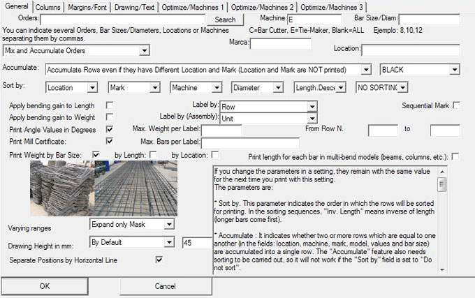
• While printing bar lists, the users settle either bar lists and labels are organized (and in what order), weighed and/or stored.
• Accumulates standard bend shapes in databases to avail them easily and automatically. An initial collection is contained that is observable in the samples page.
• Describe placing requirements graphically. All necessary rebar in a structure can appear simultaneously in the bar list and in the same label, in a high-quality placing drawing. Bar list and label paper sizes are raised so that high complexity structures can be defined perfectly. These structures are preserved in databases with the intention that it is not essential to draw them again every time.
• Computes bending dimensions from other identified dimensions.
• Works out straight and bent varying bars.
• While printing bar lists, labels or statistics, the users decide either to employ bending deductions to shearing length and/or weight.
• The length/weight relation and bending deductions are modified easily as well as configured in a different way for various machines.
• Rebar Orders are arranged with projects and units. A list and total weight for all the orders can be acquired in a project, unit, type or date range.
• Produces statistical reports. As for example, it is also understood how much is bent and how much is remaining straight for each diameter and machine, and that in a specified project, unit, type or date range.
• The previous features are contained in the 60-day trial shareware version that can be downloaded freely. The registered users will be able to access the following, export / import and network sharing.
• Export Orders (bar detailing lists) and Models (bend types) to a file in order to transfer them through e-mail or diskette to another computer. Export / Import options ensure that detailers in various locations can work on the identical project.
• Network sharing.
To download a trial version, click on the following link rebar.net
RebarWin – A powerful construction program for structural design

~~~~~~~~~~~~~~~~~~~~~~~~
Published By
Rajib Dey
www.constructioncost.co
~~~~~~~~~~~~~~~~~~~~~~~~

Monday, October 30, 2017

How to minimize efflorescence in fresh concrete masonry walls

There are different types of methods which are very useful to lessen the efflorescence in new construction of masonry walls. Efflorescence reduction processes should be initiated on a regular basis to obtain the perfect result.

To use these processes in an efficient manner, sufficient knowledge and understanding is needed. Given below, the detail information on different types of processes which are most effective to reduce probable efflorescence on bricks.


Processes to decrease efflorescence in newly constructed masonry walls:
Lessening of water penetration into masonry wall
Instantly ejecting infiltrated or condensed water from masonry wall
Avoid the connection among the bricks having diverse chemicals composition
Decrease quantity of efflorescence compounds in materials of masonry wall
Lessening of water penetration specifically wind driven rain water into masonry wall.
Various measures are undertaken throughout the construction of masonry walls to reduce water that may enter into the wall. Given below, the details of measures:
1. Create a strong bonding among masonry units and mortar: A strong bond among masonry units is possible if specific construction measures are undertaken at the time of building masonry wall.
2. As for instance, employing mortar that supports masonry units, seal both bed and head mortar joints adequately if solid units are utilized, sufficiently fill bed and meet shell joints in case hollow masonry units are utilized, combine mortar joint from ousted face of the wall.
3. Proper precautions should be taken to get rid of water penetration, particularly rain, into partly constructed walls and wall opening.
4. Movement joints in the masonry wall should have been designed, arranged and filled in an efficient manner.
5. Close masonry wall-roof interface with flashing.
6. Build overhands to safeguard masonry wall from rain water.
7. It is recommended to add either appropriate water repellent admixture to concrete masonry units or water repellent coating to the concrete masonry wall.
8. Various masonry building components like chimney cops, sills and copings should be built up from solid masonry units, reinforced concrete, corrosion resistant metals or stone.
These components should be expanded and surpassed masonry wall face by 2.5cm and flashings and weep holes should be arranged.
It is advisable to slope (preferably 1:4) these components and affix them to the masonry walls. The movement joints should be perfectly sized and positioned as well as closed satisfactorily.
For further information, go through the following article theconstructor.org

How to minimize efflorescence in fresh concrete masonry walls


Read more

~~~~~~~~~~~~~~~~~~~~~~~
Published By
Rajib Dey
www.constructioncost.co
~~~~~~~~~~~~~~~~~~~~~~~


Friday, October 27, 2017

Brief overview of Reinforcements for Slabs-on-Ground Crack Width Control

While going to create the design for slabs which are built up on the ground, give heed to the crack control factors. Given below, the brief explanation on Reinforcement details for slabs-on-ground.

The density and design of the slabs-on-ground are dependent on the cracks which are developed because of the outward loading. The computation of slab thickness is done on the basis of the assumptions of a slab that is unreinforced and uncracked.


For specific situations of slabs on ground, the steel reinforcement offers great solution. The properties of this process contain the following:
The limiting of cracks occurred because of shrinkage Use larger joint spacing that exceeds the unreinforced slabs Provision for moment capacity and strength for those areas may develop cracks The integration of reinforcement won’t avoid cracking. These elements allow for minimizing or managing the crack width developed by absolutely raising the frequency of cracks that is created.
A reinforcement design perfectly symmetrical and positioned can facilitate restraining the width of the crack and therefore the serviceability period of the slab remains unaffected.
Thickness Design Methods for Slabs-on-Ground Construction
Uncracked strength of the slab remains unaffected when there are more and more reinforcement in the slab design. The various thickness design methods like Pickett’s Analysis Method (PCA), WRI (Wire Reinforcement Institute) Design Method and COE methods are utilized for making the design of slabs on ground with reinforcement.
Reinforcement for Slabs-on ground for Crack Width Control Only
The crack width is controlled by reinforcement depending on the two factors like the joint spacing and the thickness of the slab. The crack width control can also be defined as a function of joint space and slab thickness.
A minimum steel ratio of 0.5% of the slab cross section is suggested to remove the saw cut of contraction joints.
While going to arrange the reinforcement, it is recommended to position the reinforcement bars adjacent to the surface of the slab top surface maintaining the least concrete coverage over the reinforcement.
To gather more information on recommendations, go through the following article civilgi.ga
Brief overview of Reinforcements for Slabs-on-Ground Crack Width Control


~~~~~~~~~~~~~~~~~~~~~~~~
Published By
Rajib Dey
www.constructioncost.co
~~~~~~~~~~~~~~~~~~~~~~~~


Thursday, October 26, 2017

How to design the RCC columns inexpensively

This construction article is extracted from https://theconstructor.org. The articles sheds light on how to minimize the cost by creating the design of reinforcement column as well as its construction practices and recommendations inexpensively.

Columns are considered as the most vital components in reinforced concrete structures and they ensure the security and constancy of the structure significantly.

Because of various factors, the cost of a column for each linear meter per MPa of load bearing strength fluctuates considerably. As for instance, the position of the column in the structure (outside column and inside column) and the configuration of the loads enforced on the column and others.
Given below, some other types of recommendations and measure which can reduce the cost of designing and development of reinforced concrete column significantly.
Recommendations for inexpensive design of Reinforced Concrete Columns
1. Potency of concrete used for reinforced concrete column
2. Formwork employed for casting reinforced concrete column
3. Steel reinforcements applied in the reinforced concrete column construction
4. Details of reinforcement of concrete column

Strength of Concrete for Reinforced Concrete Column
An important recommendation given for concrete strength is the utilization of utmost concrete compressive strength required to bear factored loads and least allowable reinforcement ratio. It is due to the lowest price that should be attained when such measure is undertaken as the cost of reinforcement decreases.

It is suggested that, if the least reinforcement ratio is employed for a specified column, it can minimize total column cost considerably (around 32% for concrete strength of 56MPa and 57% for concrete strength of 100MPa) relating to the case where highest reinforcement ratio is applied.
The nominal size of columns in multi storied structures is indicated on the basis of the utmost concrete compressive strength and a constraint on the highest reinforcement ratio.

If the size of column is smaller than the least permissible size at the base of the structure, then reinforcement ratio should be reduced.
Lastly, both reinforcement ratio and concrete compressive strength are reduced as the enforced factored loads decline in the upper stories.
To gather more information on recommendations, go through the following article theconstructor.org


Read more

~~~~~~~~~~~~~~~~~~~~~~~~
Published By
Rajib Dey
www.constructioncost.co

~~~~~~~~~~~~~~~~~~~~~~~~

Wednesday, October 25, 2017

Some useful tips to compute the quantity of shuttering

In this construction video tutorial, you will learn the detailed process for computing various components like plywood, bellies, nails, shuttering oil contained in shuttering.

Shuttering stands for a temporary platform that is built up with wooden planks, wooden logs, steel rods or bamboos upon which formwork is supported and finally pouring of concrete is performed. The shuttering will be disposed of as soon as concrete attains their desire strength.


Here, the calculation is based on thumb rule. In thumb rule, a constant number is selected and it is multiplied with covered area to obtain the approx quantity. The result produced through thumb rule is almost similar to the actual quantity. Therefore, by using thumb rule, it becomes easier to work out the approx quantities.
As for instance, presume there is a covered area of 2000 square feet and the RCC slab will be built up there. To work out the quantity of shuttering plywood, nails, shuttering oil, clamps etc. the following formula will be used :-
Here, the wooden shuttering is used. The quantity of the shuttering should be calculated in numbers or running foots.
1. PLYWOOD: 12 MM THICK (8′ X 4′)
= Covered area x Thumb rule
= 2000 sft x 0.02
= 40 No’s
2. WOODEN BATTENS : (3” X 3”)
= Covered area x Thumb rule
=2000 sft x 0.4
= 800 rft (running feet)
3. BEAM BOTTOM PLATES: (1.5” THICK)
= Covered area x Thumb rule
= 2000 x 0.24
= 480 rft (running feet)
To learn how to calculate the quantities of other components, watch the following video.

Read more

~~~~~~~~~~~~~~~~~~~~~~~~
Published By
Rajib Dey
www.constructioncost.co
~~~~~~~~~~~~~~~~~~~~~~~~

Tuesday, October 24, 2017

Brief discussion on lap length of bars

Development length and lap length are two vital parts of reinforcement. But there are some basic differences among development length and lap length.

While going to arrange the steel in RC structure, if the necessary length of a bar is unavailable to produce a design length then lapping is essential. Lapping occurs because of overlapping of two bars alongside to attain desired design length.

As for instance, if it is required to construct a 100 feet tall column, but 100 ft long bar will not be available in practical and caging can’t be done in this situation. So, it is necessary to cut the bars frequently to transmit the tension forces from one bar to the other at the position of suspension of bar. So, it is essential to arrange the second bar adjacent to the first bar that is suspended and overlapping should be performed. The amount of overlapping among two bars is called lap length.
For the RCC structure, if the length of reinforcement bars has to be expanded, splicing is conducted to attach two reinforcement bars for transmitting the forces to the joined bar.
LAP LENGTH FORMULA:
LAP LENGTH IN TENSION:
The lap length along with anchorage value of hooks should have been as follow :-
1. For flexural tension – Ld or 30d either is larger.
2. For direct tension – 2Ld or 30d either is larger.
The straight length of lapping should not be under 15d or 20 cm.
LAP LENGTH IN COMPRESSION: The lap length in compression should have similarity with the development length in compression calculated but not below 24d.
FOR DIFFERENT DIAMETER BARS: In case of bars with dissimilar diameter should have been spliced, the lap length is computed based on the smaller diameter bar.
LAP SPLICES: Lap splices should not be employed for the bars with greater dia than 36 mm. In this situation, welding is needed. But, in case, welding is not possible then lapping is allowed for the bars greater than 36 mm dia. supplementary spirals should have been around the lapped bars.
For more information, click on the following link dailycivil.com
Brief discussion on lap length of bars

~~~~~~~~~~~~~~~~~~~~~~~~
Published By
Rajib Dey
www.constructioncost.co
~~~~~~~~~~~~~~~~~~~~~~~~


Monday, October 23, 2017

On site demonstration of mixing and placing concrete

In this construction video tutorial you can get live demonstration of blending and positioning of concrete in the jobsite for slab or road.

Mixing: Mixing of concrete is one of the most crucial factors for obtaining good final properties and for this purpose proper equipment should be utilized.

So, it is suggested to employ ready-mixed concrete to get the best result. Mixing allocates the aggregate uniformly during the cement paste and it makes sure that all of the cement is completely saturated in water, and eliminates large air voids.

Besides, mixing separates agglomerated clusters of cement particles and facilitates air entraining admixtures to produce the perfect air void system. Undermixing can produce large flaws and therefore leads to poor strength, whereas overmixing consumes time and energy and can demolish entrained air voids. If the workability is lower, the more mixing energy and mixing time is necessary.

Placing: As soon as the concrete is blended sufficiently, it should be placed into the formwork to determine its final position and shape. If it is required to reinforce the concrete, the rebar should have been placed properly in order that the concrete can flow around it.

If the concrete mixing truck is available adjacent to the site, then the concrete should be directly poured into the forms. If it becomes difficult, the concrete is transmitted in buckets through a crane or wheelbarrow.

If it is impossible because of the necessary distance or the size of the job, the fresh concrete has to be pumped via a system of pipes or hoses to the site with the special concrete pumps. Concrete that is to be pumped contains more severe needs for workability.

If the concrete gets too dry, it will not pump properly, whereas if it gets too wet it will have a tendency to segregate. Segregation may also happen if the concrete is poured into the formwork too rapidly, because larger aggregate particles will be subject to be pushed downward.

In slab construction, the placing has to be initiated along the perimeter at one end of the work with each batch arranged against transmitted concrete earlier. It is suggested not to dump the concrete in independent piles and then level and work them jointly; nor should it be placed in large piles and carried horizontally into final position.

Watch the following video for more details.


Read more

~~~~~~~~~~~~~~~~~~~~~~~~
Published By
Rajib Dey
www.constructioncost.co

~~~~~~~~~~~~~~~~~~~~~~~~

Friday, October 20, 2017

Types of bridge and bridge components

Bridges are generally made of various types and materials and an essential part of transportation.
Bridge: It is mainly a structure which is built to stretch physical obstacles without closing the original way underneath like a body of water, valley or road etc. to make a passage over the hurdle.
There are lots of different designs from which each of them can be served for a distinct purpose and can be applied in different situations. The designs of the bridges differ as per the function of the bridge, the nature of the soil where the bridge has constructed and anchored, the material used to make it and the available funds for it.
There are mainly 4 types of bridges such as, 1) Bridges by Structure, 2) Fixed or Movable Bridges, 3) Types by Use and 4) types of Materials.
Bridges by Structure:
1. Arch bridges: The bridges use arch as a main structural element and also made with one or more articulations depended on the kind of load and stress forces endured. Ex: - “Old Bridge” in Mostar, “Bosnia and Herzegovina” and the “Hell Gate Bridge” in New York.
2. Beam bridges: They are very basic type of bridges which are supported by many beams of various shapes and sizes like inclined or V shaped. Ex: - “Lake Pontchartrain Causeway” in Southern Louisiana.
3. Truss bridges: They mainly use diagonal mesh of posts above the bridge and two most common designs are the King posts and queen posts.
4. Cantilever bridges: They are like the arch bridges in appearance but support their load through the diagonal bracing than vertical bracing and often use truss formation both in the below and the above the bridge. Ex: - “Queensboro Bridge” in New York City.
5. Tied arch bridges: Same appearance of the arch bridges but transfer weight of the bride and traffic load on the upper chord that is connected at the bottom cords in bridge foundation and these types of bridges are often called bowstring arches or bridges.
6. Suspension bridges: These kinds of bridges generally use ropes or cables from the vertical suspender for holding the weight of bridge deck and traffic. Ex: - “Golden Gate Bridge” in San Francisco.
7. Cable-stayed bridges: They use deck cables which are straightly connected to one or more vertical columns as cables generally connected to columns in two ways- harp design and fan design.
Fixed or movable types of bridges:
1. Fixed: Most of the bridges in this world are fixed and have no movable parts for providing higher clearance for river or sea transportation which flows below them. These bridges are mainly designed for staying in one place till their demolishing.
2. Temporary bridges: These bridges are made of modular basic objects which can be moved by medium or light machinery and used in military engineering or in circumstances as in time of fixing or repairing.
3. Moveable bridges: Powered by electricity and have moveable decks also.
Video Source: Sami Ullah Stanikzai
Types by use:
1. Car traffic: They are usually very common and have two or more than two lanes which are designed for carrying car and truck traffic of various depths.
2. Pedestrian bridges: They are generally found in the urban environments where car transportation way is through the soils of rough mountains, forests etc.
3. Double-decked bridges: They are naturally built to maintain as better as the traffic movement can be flowed across bodies of water or rough land. They often have large amount of car lanes and sometimes have the dedicated areas for train tracks.
4. Train bridges: Especially made for carrying one or more than one lanes of train tracks.
5. Pipelines: They can carry water, air, gas and communication cables in the water or remote lands.
6. Viaducts: They are old-fashioned structures which are created for carrying water in the prosperous areas to dry cities.
7. Commercial bridges: Modern bridges are now built as a decoration to the commercial buildings like restaurants and shops.
Types by materials: Natural materials like wood, stone, concrete and steel and some other advanced materials.

Read more

~~~~~~~~~~~~~~~~~~~~~~~~
Published By
Rajib Dey
www.constructioncost.co

~~~~~~~~~~~~~~~~~~~~~~~~

Wednesday, October 18, 2017

Various types of cofferdam

Coffer belongs to a trunk, casket or chest in which temporary structure is constructed to surround and cover an area that is prepared for excavating of the foundation of the construction. Cofferdams are applicable for structural foundation in Open Water & Open Land like bridge piers, docks, locks, dams and high ground water table.

A cofferdam is a wall with water resistance capacity that is constructed around the boundary of the projected excavation to resist the water flow into the excavation to keep the basement in dry condition.

Given below the lists of common types of coffer dams :

1) Earth Coffer Dams 2) Rockfill Coffer Dams 3) Single-Sheet Pile Coffer Dams 4) Double-wall sheet piling coffer dams 5) Braced Coffer Dams 6) cellular Coffer dams

Categories of cofferdam:

1) Earth Coffer Dams: Earth Coffer Dams are mainly built up in an area where the velocity of the current and depth of the water remains at 13 to 18 in and it is lifted 1 m over the water level. It is built up with a by amalgamating clay and sand. The Side Slopes of the bank on the water side should have been sloped with rubble Boulder to get rid of embankment from scouring. Once the coffer dam is finished, the water is pumped to wipe the interior surface. Sand bag can be utilized in an urgency.

2) Rockfill Coffer Dams: Rockfill coffer dams are constructed with rockfill. The site is often surrounded with dewatered. To safeguard against wave action, the crest and the upper portion of the impermeable membrane are supplied with rip rap. The slopes of rockfill cofferdam is built as steep as 1 horizontal to 1.5 vertical.

3) Single-Sheet Pile Coffer Dams: Single Sheet Coffer Dam is built in a very small area and it’s depth of water surpasses.5 to 6m. Initially First Guide Piles alias Timber Piles are inserted into the firm Ground that is underneath water bed. On the basis of the velocity of the Current in water, the Longitudinal runners spacing fluctuates and it is called as wales which are bolts to a timber piles at a requisite space.

Steel or Wooden Sheet is placed into the River Bed together with wales which are fastened to the wales through bolts. To make the walls stronger against the water pressure, the sheets on the two faces arc bolstered with trussed arrangement of struts and Half-filled bags of sand piled on the internal and the external faces of the sheets. Once the cofferdam is built up, the water in the surrounded area is poured out and the construction work starts.

Various types of cofferdam

Read more

~~~~~~~~~~~~~~~~~~~~~~~~
Published By
Rajib Dey
www.constructioncost.co
~~~~~~~~~~~~~~~~~~~~~~~~

Tuesday, October 17, 2017

How to settle density of various masonry walls in buildings

On the basis of loads and other factors, the density of masonry walls in a building is designed. Given below the details of perfect thickness of masonry walls necessary at the design phase :-

As for instance, it is suggested to utilize invariable masonry wall thickness among lateral supports. The lateral support for masonry is arranged with cross walls, pilasters, and structural frame members.

Concerning deviation of masonry in vertical direction, the distance among floors, structural frames and roofs should be taken into consideration if the density of masonry wall is different.
Masonry wall thickness modifies among floor and roof as well as various floors that is generally imposed to attain thermal, sound and fire requirements.
If the density of masonry wall is modified, it is suggested to expand the thicker wall to the lower support level.
Building code requirements and specifications for masonry structure (ACI 530-11) affirms that, when the density of masonry wall is developed hollow masonry units is modified, then it is necessary to arrange a layer or various layers of solid masonry units or entirely grouted hollow masonry units among the thicker masonry wall and the thinner masonry wall.
The objective of arranging solid masonry course among thicker and thinner masonry wall should be transmitting loads perfectly from the above wall (thin wall) to the wall underneath (thick wall).
There are various constraints and limitations which should be taken into consideration for masonry walls apart from the case where the walls are designed for reinforcements on the basis of the engineering principles.
The constraint related to masonry thickness for various masonry walls types are explained in detail.
Thickness Requirements for Load Bearing Masonry Wall: The density of load bearing masonry wall should have been minimum 304.8 mm (1 ft.) dense for maximum wall height of 10.668m (35 ft.).
Besides, the density of masonry wall should be raised by 101.6 mm (4in.) for each consecutive 10.668m (35 ft.) height or fractions of this height calculated from the top of the masonry wall.
There are different cases in which the above conditions are not applicable for load bearing masonry walls which range from stiffened masonry wall, top storey masonry wall, residential masonry wall, masonry wall of penthouses and roof structures, plain concrete and grouted brick masonry wall, hollow masonry wall, faced masonry wall, nonbearing masonry wall.
How to settle density of various masonry walls in buildings

Read Continue

~~~~~~~~~~~~~~~~~~~~~~~~
Published By
Rajib Dey
www.constructioncost.co
~~~~~~~~~~~~~~~~~~~~~~~~


Friday, October 13, 2017

Different types of concrete mixes

Nominal Mixes: Earlier, specifications for concrete are set the ratios of cement and fine course aggregates. This mixes of fixed cement & aggregate ratio makes sure sufficient strength in concrete and it is termed as nominal mixes.

The strength of the nominal concrete for a specified workability fluctuates significantly because of the difference of mix components. In this type of mix, all the ingredients are prearranged and their proportions are given.

Nominal mix contains volumetric batching. It is mainly utilized for comparatively insignificant and simpler concrete works. Nominal mix concrete generally utilized for concrete of M-20 or lower.

Standard Mixes: The nominal mixes of fixed cement-aggregate ratio (by volume) differentiate greatly in strength and may leads to under or over-rich mixes. Due to this the least compressive strength is contained in various specifications. These mixes are described as standard mixes.

As per IS 456-2000 standard, the concrete mixes are divided into several grades like M10, M15, M20, M25, M30, M35 and M40. Here M denotes the mix and number to the number to the stipulated 28 day cube strength of mix in N/mm2.

The mixes of grades M10, M15, M20 and M25 conform roughly to the mix proportions (1:3:6), (1:2:4), (1:1:5:3) and (1:1:2) correspondingly.

Design Mixes: In these types of mixes, a designer indicates the performance of the concrete but the ratios of mixes are defined by the producer of concrete irrespective of the minimum cement content is set.

It is the most appropriate method for choosing the mix ratios with certain materials which contain comparatively distinct characteristics.

This method facilitates the formation of concrete keeping the proper properties most inexpensively. But this type of mix does not ensure the exact mix ratios for the standard performance.

Different types of concrete mixes


 Read Continue

~~~~~~~~~~~~~~~~~~~~~~~~
Published By
Rajib Dey
www.constructioncost.co
~~~~~~~~~~~~~~~~~~~~~~~~

Thursday, October 12, 2017

About the Efflorescence on Brick masonry, its causes and treatment techniques

About Efflorescence on Brisk Masonry: It is often a white or a brown green or yellow powdery material which can be observed mainly in the winter season and it is produced from the mix of soluble salts and water.

The salt would drop on brick masonry and palpable itself as efflorescence when the water disappears and the color of the efflorescence is based on type of created salt. This efflorescence might vanish in summer but remains for the whole year.

Cause of Efflorescence on Brisk Masonry: There is a unique condition of occurring efflorescence and all the conditions should be met otherwise the brick masonry would suffer. There are three main three conditions offering the best conditions for efflorescence formation on brick masonry wall which are discussed here:
• The wall should be contained with soluble salts and that could be presented in masonry brick, mortar, adjacent soil and backing material.
• Water has to present in the brick masonry wall with the contact with soluble salt for the surface where water can be evaporated and left the salt.
• This wall will acquires pore structure for permitting the migration of soluble salt for dissolving it.
• And last of all, all the above conditions should be present for creation of efflorescence.


Factors affect the Efflorescence on Brisk Masonry:
• Temperature: An effect of high temperature falls on the efflorescence as it disappears water prior to reach the brick masonry surface.
• Water: Efflorescence is also frequent in water as water takes some time to reach the surface of the brick masonry.
• Wind
• Humidity


Sources of materials cause Efflorescence on Brisk Masonry:
• Soluble salt: There are a few sources for instance brick masonry, block masonry, mortar constituents like cement, sand, lime and admixture, grout components including cement, sand, aggregates and admixtures, contacting soil and ground water. The salts may be produced as the reactions between various constituents of brisk masonry walls and all soluble salts has the capability of producing efflorescence, like carbonates silicate, sulfate and chloride.
​• Moisture: The main source of it is the rain water especially which are wind driven and penetrate considerable water quality into the well.


Detrimental effects of Efflorescence on Brisk Masonry building: It generally damages the artistic value and the maintenance of the building. But it does not affect too much in the inner side of the building.

Control over Efflorescence on Brisk Masonry: The three conditions that are responsible for this should be controlled and proper action should be taken and as they are removal so can be washed to keep the bricks safe. But the thing is only removal and cleaning is not enough so it is required to seal the wall to avoid the problem permanently.

For more information follow theconstructor.org

About the Efflorescence on Brick masonry, its causes and treatment techniques

Read Continue

~~~~~~~~~~~~~~~~~~~~~~~~
Published By
Rajib Dey
www.constructioncost.co
~~~~~~~~~~~~~~~~~~~~~~~~

Wednesday, October 11, 2017

Illustration of stress-strain curve for concrete and steel

This construction video tutorial will teach you the detailed process for creating the design of stress-strain curve of concrete and steel by adhering to the IS 456:2000. Limit State Method is used here for these curves.

As the tensile strength of concrete as compared to compressive strength is very week, it can only withstand compressive stress. Alternatively, the tensile strength of steel is very strong and it can withstand both tensile and compressive strength.

While going to design a structure located in costal area and as per IS code the minimum grade of concrete for this structure should be M30 and concrete can’t be used below this grade. It is known that 30th characteristic strength of concrete cube of size 150 mm at 28 days. The characteristic strength is represented with the symbol as fck.
The stress-strain curve for hardened cement paste is nearly linear. The aggregate is more stiff as compared to the cement paste and will consequently deform less (i.e. contain a lower strain) under the similar applied stress.
The stress strain curve of concrete remains among those of the aggregate and the cement paste. But this alliance is non-linear over the most of the range. This non-linear behavior occurs because of formation of micro-cracks for the following reasons :-
(i) At the interface among aggregate particles and cement paste due to the differential movement among the two phases, and
(ii) Inside the cement paste itself.

These cracks are developed owing to variations in temperature and moisture and the application of load.
To learn the detailed process, watch the following video tutorial.


Read Continue

~~~~~~~~~~~~~~~~~~~~~~~~
Published By
Rajib Dey
www.constructioncost.co

~~~~~~~~~~~~~~~~~~~~~~~~

Tuesday, October 10, 2017

Download spreadsheet to assess wind load on solar panels

With wind load on solar Panels Analysis Spreadsheet, it becomes easier for installing Solar Panels on any roof. By applying this spreadsheet, one can verify whether it is reasonable to compute necessary ballast weight / fixings forces / roof loads from wind operating on Solar Panels (also known as solar modules, photovoltaic modules, photovoltaic panels or PV modules). The design adheres to BRE Digest 489.

This spreadsheet is user-friendly. The spreadsheet allows several automatic calculations and with the pop-up UK & Ireland map, it is possible to define the wind pressures on projected solar panels with a single click of the mouse. So, a normal house owner gets the ability to utilize this spreadsheet for making calculation of required ballast weight.

The spreadsheets can deal with the following types of Solar Panels:
Photovoltaic modules with ballast: This type of modules is free from any fixings into prevailing roof structure and therefore, it is not to get through current roof membrane. It makes the process simple for post-installing Photovoltaic arrays. The spreadsheet computes ballast weight necessary to resist uplift, sliding and overturning.
Photovoltaic modules fixed to flat or pitched roof: Pitched roofs are mostly found in UK and Ireland. For utilizing them to support PV modules it is required to settle load bearing components directly inside the roof structure. In this situation, it is necessary to workout fixing forces retaining a PV module and thus loads on a supporting roof. These calculations can be made with this spreadsheet.
The spreadsheet contains the following exclusive features :-
Features:
- Completely user-friendly;
- A normal house owner can use this excel sheet without any engineering knowledge;
- A comprehensible and easy to read output (all on a single page);
- Includes three PV classes:
1) PV modules mounted on or above pitched roofs;
2) PV stands mounted on flat roofs - free standing (with ballast);
3) PV stands mounted on flat roofs - mechanically fixed;
- Pop-up window for easy selection of wind loads inside UK and Ireland;
- Automatically works out dynamic wind pressure on the basis of site location, building size etc;
- User may overwrite dynamic wind pressure 'qs' and modify size effect factor 'Ca' if it was computed in another software;
- Automatically measures pressure coefficients for different situations;
- Covers open and enclosed support structures;
- For ballasted PV modules, spreadsheet evaluates sliding, overturning and uplift;
- For fixed PV modules, spreadsheet provides forces for which fixings should be designed;
- Live diagrams;
- Instant summary of results;
- Design is made by adhering to BRE Digest 489: 2004
Click on the following link to download the spreadsheet yourspreadsheets.co.uk
Download spreadsheet to assess wind load on solar panels

~~~~~~~~~~~~~~~~~~~~~~~~
Published By
Rajib Dey
www.constructioncost.co
~~~~~~~~~~~~~~~~~~~~~~~~

Monday, October 9, 2017

Specification of M50 concrete mix design

Concrete mix design belongs to the method of determining the ratios of concrete mix in terms of proportions of cement, sand and coarse aggregates.

As for instance a concrete mix of proportions 1:2:4 signifies that cement, fine and coarse aggregate are in the ratio 1:2:4 or the mix comprises of one part of cement, two parts of fine aggregate and four parts of coarse aggregate.

The concrete mix design proportions are both by volume or by mass. The water-cement ratio is normally stated in mass.
The mix design M-50 grade (with Admixture –Sikament) presented here is for reference purpose only. Actual site conditions may fluctuate and consequently, this should be modified as per the location and other factors.
M50 Grade concrete is mostly suitably in heavily reinforced structures to withstand dynamic loading.
Given below the specifications of M50 Concrete Mix Design
Grade Designation = M-50
Type of cement = O.P.C-43 grade
Brand of cement = Vikram ( Grasim )
Admixture = Sika [Sikament 170 ( H ) ]
Fine Aggregate = Zone-II
Sp. Gravity
Cement = 3.15
Fine Aggregate = 2.61
Coarse Aggregate (20mm) = 2.65
Coarse Aggregate (10mm) = 2.66
Minimum Cement (As per contract) =400 kg / m3
Maximum water cement ratio (As per contract) = 0.45
Mix Calculation: –
1. Target Mean Strength = 50 + ( 5 X 1.65 ) = 58.25 Mpa
2. Selection of water cement ratio:-
Suppose water cement ratio = 0.35
3. Calculation of water: Estimated water content for 20mm max. Size of aggregate = 180 kg /m3 (As per Table No. 5 , IS : 10262 ). As plasticizer is projected, water content is decreased by 20%.
Water content is taken as 180 X 0.8 = 144 kg /m3
For more details, click on the following link engineeringcivil.com
Specification of M50 concrete mix design

~~~~~~~~~~~~~~~~~~~~~~~~
Published By
Rajib Dey
www.constructioncost.co
~~~~~~~~~~~~~~~~~~~~~~~~