adsense analytic

Showing posts with label structural steel. Show all posts

Friday, February 22, 2019

LIMIT STATE DESIGN: (A Text-book of Reinforced Concrete Structures)

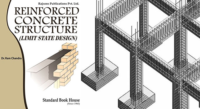
Dr. Ram Chandra, M.E. (Hons.), B.E., M.I.E., Ph.D (Roorkee), Professor of Structural Engineering has written an exclusive e-book alias LIMIT STATE DESIGN: (A Text-book of Reinforced Concrete Structures).

In this book, the author briefly explains each basic concept, elementary method, equation or theory of interest to the student of reinforced concrete design in simple manner. S.I. system of units and new code IS: 456-1978 are fully utilized in the text.

The book is specifically designed for degree, diploma and A.M.I.E. students in different branches of engineering. This book on ‘Limit State Design’ is based on the provisions of code IS: 456-1978. Both the topics of this subject, ‘Limit State of Collapse’ and ‘Limit State of Serviceability’ are clearly explained to design the reinforced concrete structures and the structural elements.

Given below, some exclusive features of the book :-

a. Each topic presented is described in detail.
b. This book is entirely composed of SI system of units and with adherence to the Indian Standard specifications (IS: 456-1978) all through the text.
c. The text of this subject is started, presented and explained in such a manner that is suitable for the students.
d. The different notations applied all through throughout this text book adhere to code of practice IS: 456-1978.

e. A number of design examples are provided in each chapter to demonstrate the theory and practice. Unsolved design problems are also provided in each chapter.
f. The diagrams clearly demonstrate the detailing of reinforcement.
g. This book abides by the current design practice.


To access the book online, click on the following link. www.amazon.in
LIMIT STATE DESIGN: (A Text-book of Reinforced Concrete Structures)

~~~~~~~~~~~~~~~~~~~~~~~~
Published By
Rajib Dey
www.constructioncost.co
~~~~~~~~~~~~~~~~~~~~~~~~


Tuesday, February 19, 2019

How to measure superimposed loads on a column

The objective of a column is to withstand axial and lateral forces and transmit them securely to the footings in the ground.

In this exclusive article, you will learn how to work out the superimposed loads on a column in a structure with some easy-to-follow steps.

Columns provide support to the floors in a structure. Slabs and beams transmit the stresses to the columns. So, it is crucial to make a strong column.

A column stands for a compression member, the effective length of which surpasses three times the minimum lateral dimension. Compression members whose lengths remain under three times the minimum lateral dimension, are constructed with plain concrete.

The axial load bearing strength of a column is derived from the follwoing formula :-

Reinforced Concrete Columns

Besides, axial loads, the column design is dependent on several other factors. Because of beam spans, wind loads, seismic loads, point loads and various other factors, the bending moments and tortional forces are produced.

A column is categorized on the basis of various factors :-

1. Depending on shape
• Rectangle
• Square
• Circular
• Polygon


2. Depending on slenderness ratio: The ratio of the effective length of a column to the minimum radius of gyration of its cross section is known as the slenderness ratio.

• Short RCC column, =< 10
• Long RCC column, > 10
• Short Steel column, =<50
• Intermediate Steel column >50 & <200
• Long Steel column >200


3. Depending on the type of loading
• Axially loaded column
• A column subjected to axial load and unaxial bending
• A column subjected to axial load and biaxial bending


4. Depending on pattern of lateral reinforcement
• Tied RCC columns
• Spiral RCC columns


Least eccentricity
Emin > l/500 + D/30 >20
Where, l denotes unsupported length of column in ‘mm’
D = lateral dimensions of column


The following types of Reinforcements for columns are found :-

Longitudinal Reinforcement
• Least area of cross-section of longitudinal bars should be minimum 0.8% of gross section area of the column.
• Maximum area of cross-section of longitudinal bars should not be in excess of 6% of the gross cross-section area of the column.
• The bars should not be below 12mm in diameter.
• Least number of longitudinal bars should be 4 in rectangular column and 6 in circular column.
• Distance of longitudinal bars measured along the perimeter of a column should not go above 300mm.


Transverse reinforcement
• It may appear in the form of lateral ties or spirals.
• The diameter of the lateral ties should not remain below 1/4th of the diameter of the greatest longitudinal bar and in no case below 6mm.


The pitch of lateral ties should not go beyond
• Minimum lateral dimension
• 16 x diameter of longitudinal bars (small) • 300mm


Helical Reinforcement
The diameter of helical bars should not remain below 1/4th the diameter of largest longitudinal and not below 6mm.
The pitch should not go above (if helical reinforcement is permitted);
• 75mm
• 1/6th of the core diameter of the column


Pitch should not remain under,
• 25mm
• 3 x diameter of helical bar
Pitch should not surpass (if helical reinforcement is not permitted)


Least lateral dimension
• 16 x diameter of longitudinal bar (smaller)
• 300mm


Reinforced Concrete Columns

Read more
~~~~~~~~~~~~~~~~~~~~~~~~
Published By
Rajib Dey
www.constructioncost.co
~~~~~~~~~~~~~~~~~~~~~~~~

Friday, February 15, 2019

POLEFDN – A excel based construction program for pole foundation analysis

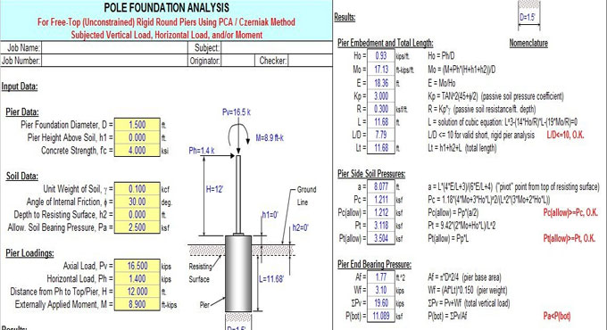
POLEFDN is a MS-excel based spreadsheet program that can be used for making analysis of a pole foundation on the assumption of the application of a inflexible round pier that is supposed free (unrestrained) at the top and exposed to lateral and vertical loads. The spreadsheet particularly makes calculation for the necessary embedment depth, the maximum moment and shear, the plain concrete stresses, and the soil bearing pressures.

This program stands for a workbook that comprises of the following six (6) worksheets:

• Doc - Documentation sheet
• Pole Fdn (Czerniak) - Pole foundation analysis for free-top round piers with PCA/Czerniak method
• Pole Fdn (UBC-IBC) - Pole foundation analysis for free-top round piers with UBC/IBC method
• Pole Fdn (OAAA) - Pole foundation analysis for free-top round piers with OAAA method

• Granular Soil (Teng) - Pole foundation analysis in granular soil with USS/Teng method
• Cohesive Soil (Teng) - Pole foundation analysis in cohesive soil with USS/Teng method


Given below, some useful features of the program :-

This program can deal with both horizontally and vertically applied loads. The vertical load may contain an associated eccentricity that leads to an additional overturning moment to be always assumed to add directly to the overturning moment formed with the horizontal load.

This program guesses that the top of the pier remains at or over the top of the ground surface level.

This program guesses that the actual resisting surface remains at or under the ground surface level. It takes into account any weak soil or any soil that is detached at the top.

The "Pole Fdn(Czerniak)" worksheet guesses that the inflexible pier rotates about a point situated at a distance, 'a', under resisting the surface. The highest shear in pier is supposed to be at that 'a' distance, whereas the maximum moment in the pier is supposed to be at a distance = 'a/2'.

The "Pole Fdn(Czerniak)" worksheet works out the "plain" (unreinforced) concrete stresses, compression, tension, and shear in the pier. The corresponding permissible stresses are also set on the basis of the strength (f'c) of the concrete. It is performed to check whether the steel reinforcing is actually necessary or not. The permissible tension stress in "plain" concrete is supposed to be equivalent to 10% of the value of the permissible compressive stress.

The "Pole Fdn(Czerniak)" worksheet measures the actual soil bearing pressures along the side of the pier at equivalent distances to 'a/2' and 'L'. The relevant permissible passive pressures at those locations are set for comparison.

As all overturning loads are protected with the passive pressure against the embedment of the pier, this program guesses that the pier functions in direct end bearing to withstand only the vertical loading. The bottom of pier bearing pressure is measured that contains the self-weight of the pier, assumed at 0.150 kcf for the concrete.

To download the program, click on the following link www.cesdb.com

POLEFDN รข€“ A excel based construction program for pole foundation analysis

~~~~~~~~~~~~~~~~~~~~~~~~
Published By
Rajib Dey
www.constructioncost.co
~~~~~~~~~~~~~~~~~~~~~~~~

Monday, April 9, 2018

Steel Beam Connections

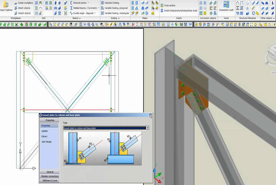
Steel beam connections are used to join different members of structural steel frame work; Steel Structure Collections attach various members to make them a unit.

Steel connections

Connections are like the structural elements which are used to connect various members of structural steel frame work and Steel Structure is a collection of different member like Beams, Columns which are joined with one another at member ends fasteners to show a single composite unit.

Types

Generally steel beam connections are used in structures and all beam connections are categorized into two groups like framed and seated connections. The framed steel beam is connected to the supportive steel element by fittings and the seated steel beam is placed on seat like to the case where beam is located on masonry walls.
This article mainly focuses on the different types of steel beam connections with their working process, steel beam connections are divided into following types:

  • Bolted Seated Steel Beam Connection
When a beam is joined with a support, a column or a girder with web connection angles, then the joint is names as ‘framed’. Here every the connections must be plotted for the end reaction of the beam, its type, size and toughness of the fasteners and the capacity of bearing strength of core materials should be done. In these connections, the steel beams are connected in a way as supporting elements whether it is steel columns with the web connection angles and the minimum length of connection angle must be at least half of the beam clear web depth. The proportion is specified for right stiffness and solidity; there are different sizes of bolted framed connections besides their capability given by codes. This connection is required to enhance the rapidity of the design and minimum connection is enough to resist the applied load for making the design more economical.

  • Bolted Framed steel connections
In seated connection beams right sizes, capabilities and other data are filed in the AISC Manual, there are mainly two main types of bolted seated connections one of them is the soft bolted seat connections and hard bolted seat connection. When the reactions at the end of the beam are big then it is approved as hard or stiffened seat connections for their satisfactory capacity to oppose large forces. But the capability of soft or unstiffened seat connection is blocked for limited bending capacity of seat angle leg. The most helpful thing is that the beam in this connection can be invented economically and seat would give immediate support in the erection period.

  • Welded framed steel beam connection

This beam connection can be found in different sizes with their capabilities are available and supplied by codes. The weld of connection is bound to direct shave stress which caused by loads on the beam which beam affect weld pattern so the stresses are needed to be considered. The part of the welding is executed in a field where it seems difficult to get high quality weld for the movements of steel members caused by winds or other factors.

  • Welded seat steel beam connection
It is same as to bolt seat connection but used for bonding than bolts and the pressure on the beams affect the weld pattern curiously and create stress which need to be planned. The welded seat connections are of two types: unstiffened and stiffened, unstiffened is used for small loads and the stiffened is used to bear large loads. Use bolts to connect beam bottom border to the seat and the blots can be removed at their position after the end of their welded process. This connection is not requested from environmental point of view and worker as the connection can’t be erected easily.

  • End plate steel beam connection
This kind of connection is made through using the welding art and the end plate is joined to the beam by weld for its capability and size which are controlled by shear capacity of the beam web connected with the weld. The applied load on the connection at last of the member doesn’t have irregularities and the plate connections are of various types like flexible, semi-rigid and rigid. The fabrications and cuttings must be connected with the extreme care to stop errors but the end plate connections are not applicable to tall steel structures.

  • Special steel beam connections
These connections are used for the case where the preparations of the structural element are placed in a way that standard connections can’t be used. The connections can transfer moments into the columns as per degree of fixity of the connections and the higher degree of fixity of the beam connection is the greater ability to transfer the moments into the columns.

  • Simple, rigid and semi-rigid connections
Moment connections can transfer the forces in the beam sides to the column and this transfer moment must be provided for more and usually free of the shear connection needed to support the beam reaction. Simple, rigid and semi-rigid connections are designated simply to support beams and columns for shear only and leave the ends free to move under load. Besides carrying shear they provide enough rigidity to hold virtually unchanged angles between connected members.


Steel Beam Connections

~~~~~~~~~~~~~~~~~~~~~~~~
Published By
Rajib Dey
www.constructioncost.co
~~~~~~~~~~~~~~~~~~~~~~~~

Tuesday, October 31, 2017

RebarWin – A powerful construction program for structural design

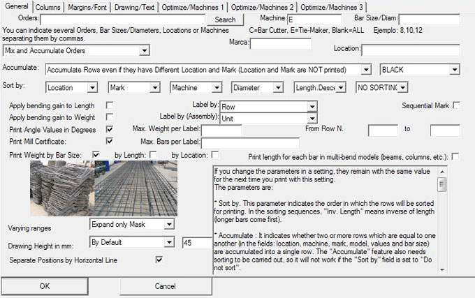
RebarWin is a useful software for rebar detailing. This software program provides huge benefits to the rebar detailers who deal with construction and civil engineering projects.

The main features of RebarWin are:

• Produces sorted, weighed and accumulated bar lists.
• Prints labels to attach it with the rebar bundles.
• Supports Imperial, SoftMetric and European Metric Measuring Systems.
• Ability to exports to Excel® SpreadSheet.
• While printing bar lists, the users settle either bar lists and labels are organized (and in what order), weighed and/or stored.
• Accumulates standard bend shapes in databases to avail them easily and automatically. An initial collection is contained that is observable in the samples page.
• Describe placing requirements graphically. All necessary rebar in a structure can appear simultaneously in the bar list and in the same label, in a high-quality placing drawing. Bar list and label paper sizes are raised so that high complexity structures can be defined perfectly. These structures are preserved in databases with the intention that it is not essential to draw them again every time.
• Computes bending dimensions from other identified dimensions.
• Works out straight and bent varying bars.
• While printing bar lists, labels or statistics, the users decide either to employ bending deductions to shearing length and/or weight.
• The length/weight relation and bending deductions are modified easily as well as configured in a different way for various machines.
• Rebar Orders are arranged with projects and units. A list and total weight for all the orders can be acquired in a project, unit, type or date range.
• Produces statistical reports. As for example, it is also understood how much is bent and how much is remaining straight for each diameter and machine, and that in a specified project, unit, type or date range.
• The previous features are contained in the 60-day trial shareware version that can be downloaded freely. The registered users will be able to access the following, export / import and network sharing.
• Export Orders (bar detailing lists) and Models (bend types) to a file in order to transfer them through e-mail or diskette to another computer. Export / Import options ensure that detailers in various locations can work on the identical project.
• Network sharing.
To download a trial version, click on the following link rebar.net
RebarWin – A powerful construction program for structural design

~~~~~~~~~~~~~~~~~~~~~~~~
Published By
Rajib Dey
www.constructioncost.co
~~~~~~~~~~~~~~~~~~~~~~~~

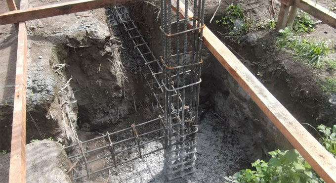
Tuesday, February 2, 2016

Automatic structural steel fabrication system

This construction video shows the detailed process for structural steel fabrication automatically. Steel fabrication is the process for developing metal structures through cutting, bending, and assembling processes.


It is a value added procedures that engrosses the construction of machines and structures out of several raw materials. A fabrication shop will bid on a job, generally on the basis of the engineering drawings, And if the contract is alloted the project will be built up by the contraftor.


~~~~~~~~~~~~~~~~~~~~~
Published By
Rajib Dey
~~~~~~~~~~~~~~~~~~~~~