adsense analytic

Showing posts with label building design. Show all posts

Saturday, June 22, 2019

How to create exact building plan for a G+1 storey building

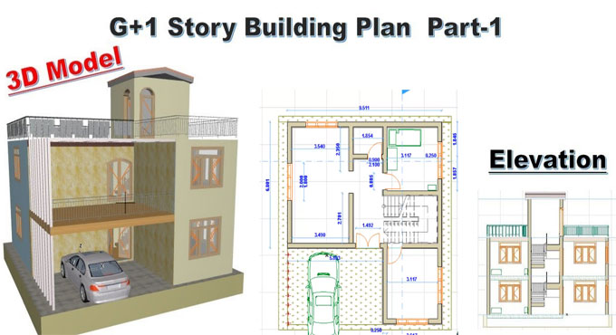
In this exclusive civil engineering video tutorial, you will get some vital information on how to develop perfect building plan for any G+1 story building. Besides, you will also get details about section, elevation and 3D model.
The area of the building = 14.9 x 14.5 square meter. The building contains space for car parking, hall room, one bed room, kitchen & dining, bathroom as well as staircase.
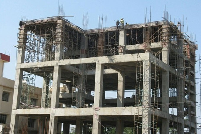
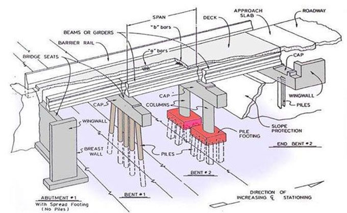
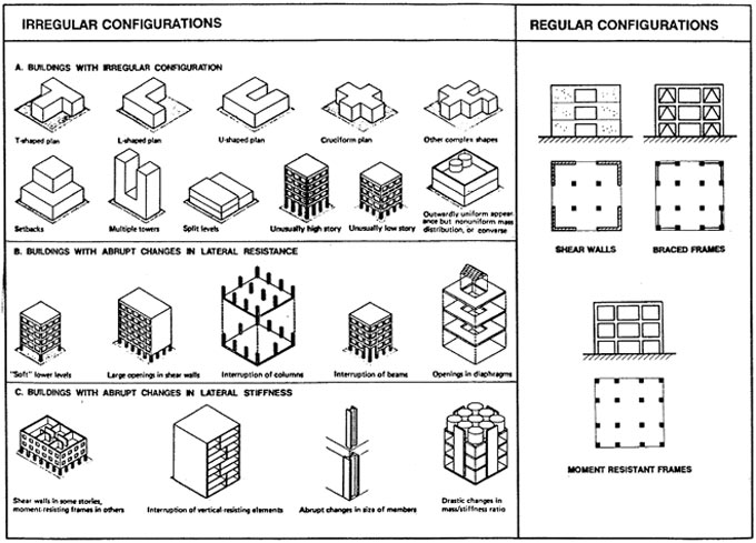
The buildings should have firmly interconnected beams and columns which are known as building frames.
The loads from walls and beams are transmitted to beams and consequently rotation of beams occurs. As beams are firmly attached with column, the rotation of column also occurs. Therefore, any load enforced to anywhere on beam is distributed by entire network of beam and columns.
The building design involves the following steps :-
Step 1: Plan the fairly accurate layout of the building.
Step 2: Workout dead and snow load.
Step 3: Design steel roof decks:
Step 4: Choose open web steel joists
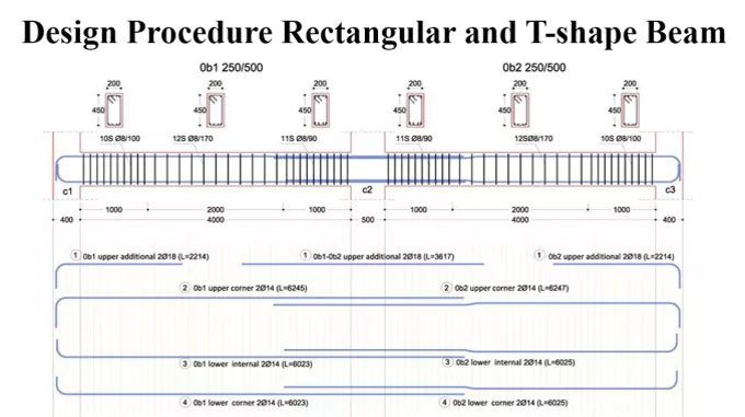
Step 5: Design beam.
Step 6: Design column.
Step 7: Design steel column bore plates.
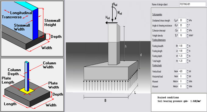
Step 8: Design footing
Step 9: Create engineering drawing.
Step 10: Final check and submission.
To get more detail, go through the following video tutorial.
How to create exact building plan for a G+1 storey building

~~~~~~~~~~~~~~~~~~~~~~~~
Published By
Rajib Dey
www.constructioncost.co
~~~~~~~~~~~~~~~~~~~~~~~~

Friday, February 22, 2019

LIMIT STATE DESIGN: (A Text-book of Reinforced Concrete Structures)

Dr. Ram Chandra, M.E. (Hons.), B.E., M.I.E., Ph.D (Roorkee), Professor of Structural Engineering has written an exclusive e-book alias LIMIT STATE DESIGN: (A Text-book of Reinforced Concrete Structures).

In this book, the author briefly explains each basic concept, elementary method, equation or theory of interest to the student of reinforced concrete design in simple manner. S.I. system of units and new code IS: 456-1978 are fully utilized in the text.

The book is specifically designed for degree, diploma and A.M.I.E. students in different branches of engineering. This book on ‘Limit State Design’ is based on the provisions of code IS: 456-1978. Both the topics of this subject, ‘Limit State of Collapse’ and ‘Limit State of Serviceability’ are clearly explained to design the reinforced concrete structures and the structural elements.

Given below, some exclusive features of the book :-

a. Each topic presented is described in detail.
b. This book is entirely composed of SI system of units and with adherence to the Indian Standard specifications (IS: 456-1978) all through the text.
c. The text of this subject is started, presented and explained in such a manner that is suitable for the students.
d. The different notations applied all through throughout this text book adhere to code of practice IS: 456-1978.

e. A number of design examples are provided in each chapter to demonstrate the theory and practice. Unsolved design problems are also provided in each chapter.
f. The diagrams clearly demonstrate the detailing of reinforcement.
g. This book abides by the current design practice.


To access the book online, click on the following link. www.amazon.in

LIMIT STATE DESIGN: (A Text-book of Reinforced Concrete Structures)

~~~~~~~~~~~~~~~~~~~~~~~~
Published By
Rajib Dey
www.constructioncost.co
~~~~~~~~~~~~~~~~~~~~~~~~


Thursday, February 21, 2019

Some useful guidelines to work out the total loads on a column & footing

This article is about calculation of loads for column and footings design.
The following types of loads operate on a column :-
1. Self weight of the column x Number of floors
2. Self weight of beams per running meter
3. Load of walls per running meter
4. Total Load of slab (Dead load + Live load + Self weight)
The columns are also susceptible to bending moments which should be included in creating the final design. There are different types of advanced structural design software like ETABS or STAAD Pro which can be applied to design a good structure efficiently. The calculation for structural loading In professional practice is based on some fundamental assumptions.
For Columns: Self weight of Concrete is approximately 2400 kg per cubic meter that is identical to 240 kN. Self weight of Steel is approximately 8000 kg per cubic meter. Suppose a large column having size of 230 mm x 600 mm with 1% steel and 3 meters standard height, the self weight of column is approximately 1000 kg per floor, that is identical to 10 kN. So, here, the self weight of column is taken as among 10 to 15 kN per floor.
For Beams: The calculation is same as above. Suppose, each meter of beam contains dimensions of 230 mm x 450 mm exclusive of slab thickness. So, the self weight is approximately 2.5 kN per running meter.
For Walls: Density of bricks differs among 1500 to 2000 kg per cubic meter. For a 6″ thick wall with 3 meter height and 1 meter length, the load can be measured per running meter equivalent to 0.150 x 1 x 3 x 2000 = 900 kg which is equivalent to 9 kN/meter. The load per running meter can be measured for any brick type by following this method.
For autoclaved, aerated concrete blocks like Aerocon or Siporex, the weight per cubic meter should remain among 550 to 700 kg per cubic meter. If these blocks are utilized for construction, the wall loads per running meter remains as low as 4 kN/meter, that leads to cutback in construction cost.
For Slab: Suppose the thickness of the slab is 125 mm. Now, each square meter of slab contains a self weight of 0.125 x 1 x 2400 = 300 kg that is similar to 3 kN. Suppose, the finishing load is 1 kN per meter and superimposed live load is 2 kN per meter. So, the slab load should remain 6 to 7 kN per square meter.
Factor of Safety: Finally, once the calculation of the entire load on a column is completed, the factor of safety should also be taken into consideration. For IS 456:2000, the factor of safety is 1.5.
Some useful guidelines to work out the total loads on a column & footing

~~~~~~~~~~~~~~~~~~~~~~~~~~
Published By
Rajib Dey
www.constructioncost.co
~~~~~~~~~~~~~~~~~~~~~~~~~~

Saturday, February 16, 2019

Common structural members in a building

In this civil engineering article, you will get detail information on different types of structural members in a building.

Beam: Beam stands for a flexure member of the structure. It is exposed to transverse loading like vertical loads, and gravity loads. With these loads, shear and bending are formed inside the beam. Beams belong to horizontal structural members to bear a load successfully.

Beam is generally applied for withstanding vertical loads, shear forces and bending moments.

Columns: A long vertical member that mostly undergoes compressive loads & buckling loads is known as column. Columns stand for vertical, structural members of a structure. They transmit load from beams to footings. Columns are mostly utilized to support beams or arches on which the upper sections of walls or ceilings rest.

Strut: Strut is a compressive member of a structure. This structural member is driven from opposite ends. The purpose of a strut is to withstand compression.

Ties: A tie stands for a structural member that is extended from opposite ends. A tie mainly deals with tension.

Beam-Column: A structural member that is exposed to compression and flexure is known as beam column.

Grid: A group of beams which overlap each other at right angles and exposed to vertical loads is known as grid.

Cables and Arches: Cables are normally suspended at their ends and are granted to sag. The forces then turn to pure tension and are headed along the axis of the cable. Arches have the similarity with cables apart from they are inverted. They bear compressive loads which are directed along the axis of the arch.

Plates and Slabs: Plates belong to three dimensional flat structural components generally constructed with metal which are frequently utilized in floors and roofs of structures. Slabs are identical to plates apart from that they are normally constructed with concrete.

Common structural members in a building

Read Continue
~~~~~~~~~~~~~~~~~~~~~~~~
Published By
Rajib Dey
www.constructioncost.co
~~~~~~~~~~~~~~~~~~~~~~~~

Monday, February 11, 2019

Why curing of concrete is important?

Curing offers the following functionalities :

1. Resist the concrete from getting dried throughout hydration. If this happens, the strength of the concrete is reduced significantly. The damage can’t be recovered. If concrete is dried, the cement grains will produce an impervious layer of hydration product around them, and it will resist recurring of hydration, though several occasion it is dampened again.

2. To maintain heat at the surface.

Curing is carried out for the following purposes :-

a. To get rid of frost damage (under 5°C, 40°F)
b. To raise initial strength
c. To minimize temperature gradients


When low temperatures decrease initial strength, the effect does not remain for a long time in case the concrete has not frozen, and it is consequently retained at higher temperatures. As a result, a sample that is retained at 5°C (40°F) will not completely hydrate (specifically if there exist a pozzolan in it), but even after a number of months it will hydrate again with higher temperature.

Since hydration occurs more slowly, cements containing pozzolans and GGBS normally need longer curing. It is therefore necessary that these concretes should be recognized on site, and cured sufficiently. The pozzolanic reaction will then produce extra hydration products to block some of the pores among the cement grains, and attain good strength.

Given below, some recognized process of curing :

• Cover materials (e.g., columns) in polythene once the shutters are detached.
• Spray with curing membrane as soon as detachment of shutters.
• Wrap slabs with polythene (and pour ground slabs on polythene).
• For heat retention, the polystyrene should be utilized on the back of shutters (particularly, steel ones)
• Just leave shutters in exact position for a few extra days (particularly wooden ones).
• 50 mm of sand is well suited on slabs.
• Ponding (i.e., developing a pool on the concrete surface) will be definitely most suitable.


Note about curing:

• Ensure that curing is provided immediately as possible. A few hours may provide significant effect.
• Spray-on curing membranes are less effective, and in windy conditions they should not be used. On complicated areas (like columns), they should be used as there is no other options.
• Keep in mind that PFA, GGBS and, especially, CSF requires much better curing (frequently 5 days, in spite of 3 days).
• Allowing the bleed water to dry off will lead to more bleeding, and plastic cracking.
• Slabs on ground should contain a polythene sheet that is arranged under them, to get rid of excessive water absorption with dry soils.


Why curing of concrete is important?

Read Continue
~~~~~~~~~~~~~~~~~~~~~~~~~~
Published By
Rajib Dey
www.constructioncost.co
~~~~~~~~~~~~~~~~~~~~~~~~~~

Thursday, February 7, 2019

Details about various sections of bridge

All the major elements are arranged within three main bridge areas – Foundation (that retains the shallow or deep base of the bridge and transmits it’s load to the bearing strata, it comprises of foundations underneath the primary span of the bridge and the abutments underneath starting points of the bridge), Substructure (piers, abutments, spandrels, caps, bearings, and other elements that retains the top part of construction) and Superstructure (all the segments of the bridge which are assembled on top of the supporting substructure system, it comprises of various components like decking, girders, slab, and everything arranged over the main deck like posts, steel truss system, bridge girder, cable-stayed system, cable suspended systems and more).

The followings are the major elements of the modern bridges:

Abutment – Endpoints of the bridge. They are reinforced to facilitate withstanding extreme lateral pressures.

Pile (also called as beam, footing, and pier) – It stands for reinforced concrete post that is pushed into the ground to function as the leg or support for the bridge. The extent among piles is worked out to provide support to the rest of the structure that will be placed on top of them.

Cap – Cap is located on top of the pile beam that gives extra support and distributes the load to the piles underneath. The amalgamation of Pile and Cap elements is known as Bent.

Girder or Span – It is one of the major components of the bridge that attaches all the Piles beams. It involves several simple spans, a single continuous span that is supported with numerous beams, cantilever spans and cantilever spans with the suspended span among them. They are normally formed with metal or reinforced concrete as well as in the form of haunches girded be bear more load. Girder sections are usually not formed with a simple block of material but built up with truss network (or Orthotropic beams) that enhance their resistance capacity against load. Girders are also utilized as a part of rigid frame network where they are totally attached with frame legs (that may appear as inclined or in V shape).

Superstructure truss network – Truss network that provides supports to travel surface is built with three basic ways – Deck truss where traffic passes on top of truss network, Pony truss where truss network passes among two parallel walls of trusses, and via truss that includes extra cross-braced truss network over and below the traffic.

Deck beam – Simple continuous decks are created with metal or reinforced concrete. They comprise of sub-components like approach slab (attaches main bridge decking with the ground on both sides of the bridge), expansion joint, drainage scupper, curb, running surface, footpath.

Barriers – These are the sides of the bridge decks normally contain extra barrier components like railings, handrails and ground fixtures.

Arch – Arches on the bridges are differentiated with the number of hinges they contain (normally among zero or three) which ascertain the volume of stress and load they can bear securely, and the type of material they are built up (solid material, truss system). Arches underneath the bridge are known as spandrel-braced (cantilever) or Trussed deck arch.

Spandrel – Spandrels belong to the almost triangular space among the main pillar of the bridge and decking. Stone bridges employ filled “closed” spandrels deck arches, whereas the modern bridges are constructed with metal having open spandrel deck arch configurations.

Truss – Framework is created by attaching triangles and other forms that disperse load and stress forces across its whole structure. They are generally segregated into various categories like simple truss (King and Queen posts), covered bridge truss (multiple kingpost truss, Howe truss, long truss, Burr arch truss, town lattice truss, Haupt, Smith, Partridge and Child truss), Pratt truss (and it’s many variations), Whipple truss, Warren truss variations, Howe truss, Lenticular truss, Fink truss, multiple Cantilever truss variations, and suspension truss arches.

Details about various sections of bridge

Read more
~~~~~~~~~~~~~~~~~~~~~~~~~~
Published By
Rajib Dey
www.constructioncost.co
~~~~~~~~~~~~~~~~~~~~~~~~~~

Friday, December 21, 2018

Some useful tips on reinforced concrete design

While designing the reinforced concrete members, it is necessary to check the steel reinforcement in jobsite prior to arrange concrete. Besides, ensure the concrete foundations, beams, columns, etc. are constructed as per design norms. Often, it is observed that steel beam stirrups employed in reinforced concrete design, are not installed properly.

The beam stirrups are extensively utilized in residential construction. In order to produce perfect architectural design and satisfy building occupant requirements, the sizes of concrete beam are made thinner and their lengths are increased.

In our experience, this has been the result of architectural design and. The higher cost of foundation components like drilled piers is also a major concern. To lessen the requirement of extra piers, the lengths of concrete beam are raised and it leads to the application of steel stirrups.

Concrete beams differ in depth. The shear strength of the beam will be increased by making beam deeper. For insufficient depth, steel stirrups should be included to raise the shear strength of the beam. These stirrups generally belong to one piece of steel that is twisted into a rectangular shape. Often small diameter steel like #3 and #4 rebar is applied. The stirrup normally wraps around the bottom and top bars of the beams.

It is essential to indicate the size, distance and position along the length of the beam where the stirrups will be assigned. Besides, the dimensions of stirrup should also be indicated in the sections in order that the stirrup is manufactured before installation.

Stirrups are suitable for the areas of high shear, like bearing points and under large point loads.

The installer should take proper care for fabrication of the stirrup from one piece of steel and sufficiently overlap each end (speak to the Structural Engineer or refer to the ACI code for variations). Sometimes, the stirrup is not pre-fabricated and the installer attempts to produce the stirrup in the field, once the horizontal bars are already in position. It is normal since the stirrup is built up from two pieces with insufficient lap splice.

The method is simple to set up a stirrup simultaneously the horizontal reinforcement is being installed. To avoid last-minute modifications, it is recommended to consult with the Structural Engineer with any confusion regarding size, shape, spacing and installation of stirrups before inspection.

Some useful tips on reinforced concrete design

Read more
~~~~~~~~~~~~~~~~~~~~~~~~
Published By
Rajib Dey
www.constructioncost.co
~~~~~~~~~~~~~~~~~~~~~~~~

Friday, December 14, 2018

The construction process and benefits of cavity walls

Cavity wall stands for a double wall that comprises of two individual walls of masonry known as skins or leaves which are detached with an air space and connected jointly through metal ties at proper distances.

These walls are normally used as outside walls but sometimes used also as interior walls because of good sound.

Construction Methods of Cavity Wall

The two leaves of a cavity wall contain same thickness when it belongs to a non load bearing wall or the inside leaf becomes thicker as compared to exterior leaf to comply with the structural needs.

The interior and exterior skins of the wall are sufficiently knotted jointly with special wall ties involving minimum five ties per square meter of wall.

The cavity wall should not remain under 40mm nor over 100 mm in width.

A vertical damp proof course should be provided at window and door reveals so that moisture can not penetrate in the wall. The damp proof course should be adaptable.

Building Regulations For Cavity Wall
As per the norms of building codes, the double wall should be normally 265 mm or 275 mm thick and comprises of 102.5 mm interior and exterior skins and 60-70 mm cavity (sufficient for 2 storied domestic building).


The interior leaf should be raised to 215 mm or more in thickness encountering heavier load or floors. For stone faced buildings, the exterior leaf should be 103-206 mm and interior leaf should be 102.5 mm. The width of cavity in between differs from 50 – 70 mm.

Benefits of cavity walls

1. In these types of walls, there are no scopes for entering of moisture from the exterior wall to the interior wall.
2. The layer of air in the cavity does not transmit heat and minimizes the transition of heat from the exterior face to interior face.
3. It functions as damp barrier and lessens the cooling cost of the building.

4. The cost of building up a 275 mm cavity wall will be low as compared to build up a 328 mm solid wall.
5. It is inexpensive as compared to exterior or interior wall insulation.
6. It retains the thickness of the existing wall.
7. Minimum disruption is required for set up.
8. It can minimize condensation significantly.


The construction process and benefits of cavity walls

Read more
~~~~~~~~~~~~~~~~~~~~~~~~
Published By
Rajib Dey
www.constructioncost.co
~~~~~~~~~~~~~~~~~~~~~~~~

Tuesday, December 11, 2018

How to design rectangular and T shape beam

Beams are defined as members which are exposed to flexure. So, it is important to give attention to the analysis of bending moment, shear and deflection.

When the bending moment operates on the beam, bending strain is created. The resisting moment is formed with internal stresses. Under positive moment, compressive strains are developed in the top of the beam and tensile strains in the bottom.

Concrete is weak against tensile strength and it is not perfect for flexure member by itself. The tension side of the beam will collapse prior to failure of compression side when beam is exposed to a bending moment devoid of the reinforcement. To resolve this issue, steel reinforcement is provided on the tension side. The steel reinforcement withstands all tensile bending stress as tensile strength of concrete is zero when cracks are formed.

Rectangular beam

Accept the depth of beam with the ACI code reference, least thickness until the deflection is considered.
Accept the beam width (ratio of width and depth is approx 1:2).


Calculate self-weight of beam & design load.
Work out factored load (1.4 DL + 1.7 LL).
Calculate design moment (Mu)
Work out maximum possible nominal moment for singly reinforced beam (φM n ).


Determine reinforcement type by making comparison between the design moment (M u ) and the maximum possible moment for the singly reinforced beam (φM n ). If φM n remains under Mu, the beam should be designed as a doubly reinforced beam otherwise the beam should be designed with tension steel only.

Find out the moment strength of the singly reinforced section (concrete-steel couple).

Calculate the necessary steel area for the singly reinforced section.
Determine an essential residual moment, deducting the total design moment and the moment capacity of the singly reinforced section.
Calculate the extra steel area from the required residual moment.
Calculate the total tension and compressive steel area.
Design the reinforcement with the selection of the steel.
Verify the actual beam depth and assumed beam depth.


T-shape Beam

Calculate the design moment (Mu ).
Presume the effective depth.
Choose the effective flange width (b) depending on ACI criteria.


Workout the practical moment strength (φM n ) anticipating the total effective flange is supporting the compression.

When the practical moment strength (φM n ) is greater than the design moment (Mu ), the beam is measured as a rectangular T-beam with the effective flange width b. If the practical moment strength (φM n ) is not more than the design moment (Mu ), the beam will operate as a true T-shape beam.

Determine the approximate lever arm distance for the internal couple.
Work out the approximate required steel area.


Design the reinforcement
Verify the beam width
Calculate the actual effective depth and analyze the beam


How to design rectangular and T shape beam

Read Continue


~~~~~~~~~~~~~~~~~~~~~~~~
Published By
Rajib Dey
www.constructioncost.co
~~~~~~~~~~~~~~~~~~~~~~~~

Monday, October 22, 2018

Brief overview of Seismic Design

The mass of the building to be designed manages seismic design apart from the building stiffness, since earthquake produces inertia forces which are proportional to the building mass.

If the buildings are designed to function elastically throughout earthquakes devoid of any damage, the project becomes economically illogical.

Because of this, it is essential for the structure to endure damage and thus disperse the energy input to it throughout the earthquake. So, the conventional earthquake-resistant design philosophy needs that normal buildings should have the capacity to withstand earthquake.

Minor (and regular) shaking with no damage to structural and non-structural elements.

Moderate shaking with small damage to structural components, and some damage to non-structural elements.

Extreme (and unusual) shaking with damage to structural components, but with NO collapse (to save life and property inside/adjacent to the building.

SEISMIC DESIGN FACTORS: The following factors provide a great impact on the building design. Serious attentions should be given in the design phase.

Torsion: Objects and buildings contain a center of mass i.e. a point by which the object (building) is balanced devoid of rotation taking place. If the mass allotted consistently then the geometric center of the floor and the center of mass may meet.

If the mass is allotted unequally, the center of mass is placed outside of the geometric center and it leads to "torsion" producing stress concentrations. A specific amount of torsion is indispensable in each building design. If the masses are organized uniformly, it will lead to balanced stiffness against either direction and maintain torsion within a agreeable range.

Damping: Usually, the buildings are poor resonators to dynamic shock and disperse vibration by engrossing it. The natural vibration is consumed with damping.

Ductility: Ductility is the property of a material (like steel) to bend, flex, or move, but fails due to happening of significant deformation. Non-ductile materials (like weakly reinforced concrete) fail unexpectedly by crumbling. It is possible to attain superior ductility with carefully detailed joints.

Strength and Stiffness: Strength is a property of a material to defy and tolerate applied forces within a safe limit. Stiffness of a material refers to a degree of resistance to deflection or drift (drift being a horizontal story-to-story relative displacement).

Building Configuration: This term defines a building's size and shape, and structural and nonstructural components. Building configuration establishes the way seismic forces are circulated within the structure, their relative magnitude, and problematic design concerns.

Brief overview of Seismic Design

Read more
~~~~~~~~~~~~~~~~~~~~~~~~
Published By
Rajib Dey
www.constructioncost.co
~~~~~~~~~~~~~~~~~~~~~~~~

Friday, June 8, 2018

New technology in earthquake engineering to resist collapsing of the structures

It is the big challenge for the structural engineers to develop earthquake resistance structures.
An Earthquake resistant structure should have the capacity to resist abrupt ground shaking to reduce the damages to the structure.
Though the reinforced Concrete contains sound earthquake resistance capacity of buildings but owing to the substandard mix design of concrete and improper curing the reinforced concrete lost it’s desired compressive strength and it leads to collapsing of structure during an earthquakes.
Recently, a new innovation is launched in earthquake engineering where the curtain of cables is affixed to ground to significantly enhance the earthquake resistance strength of the building.
In these technology threads are used which are created with thermoplastic carbon fibre composite. These threads are fastened and knotted to produce a strong flexible rod which is 90% lighter as compared to reinforcement bars and contain the equivalent strength.
To resist earthquake successfully, these composite rods are fastened & secured from the roof to the ground and set up around the building. Rods are also set up inside the building to make the interior walls stronger.
These Composite threads are formed with textiles so that the rods can expand and pull the structure back in opposite direction to withstand shaking of the structure.
When an earthquake occurs, in case the building is pushed towards left side, the threads or rods located on right side pulls it back to retain the building in exact position and significantly reduces the structural damage and human death.
For online demonstration of this new technology, go through the following video tutorial.
Video Source: TomoNews US

~~~~~~~~~~~~~~~~~~~~~~~~
Published By
Rajib Dey
www.constructioncost.co
~~~~~~~~~~~~~~~~~~~~~~~~

Thursday, June 7, 2018

Various types of notations used in the construction of concrete culvert design

The following notations are used in the drawing of concrete culvert design.

With notation, it is possible to make clear communication among various project stakeholders. Notation helps in avoiding mistakes in any construction project.

A’ = The valid contact area of a footing, measuring unit is in square metres
A = A detailing dimension for culverts that contains skewed ends, measuring unit is in mm
B = Depth of the bottom slab of a box culvert, measuring unit is in mm
B = Gapping among adjoining bars with reference to detailing tables, measuring unit is in mm
C = A coefficient that is applied in finding out the quantities of reinforcing bar.
CANBAS = Canadian Bridge Analysis System
c’ = the valid cohesion among the base of the footing and the soil at the ULS, with reference to CHBDC. kPa
CHBDC = Canadian Highway Bridge Design Code, 2000 Edition
CGSB = Canadian General Standards Board
F = Width of footing for open footing culverts, measuring unit is in mm
F1 = A reinforcing bar spacing factor, measuring unit is in mm-1
HULS = maximum factored horizontal reaction at the level of the base of the footing at the ULS, kN
Lc = Culvert length that is calculated the longitudinal axis, measuring unit is in m
OCPA = Ontario Concrete Pipe Association

OMBAS = Ontario Modular Bridge Analysis System
OPSS = Ontario Provincial Standard Specifications
S = Culvert distance that is calculated perpendicular to the longitudinal axis of the culvert, measuring unit is in mm
SLS = Serviceability limit states, in accordance with CHBDC

T = Depth of top slab of culvert, mm tan φ’ effective friction coefficient for concrete cast against soil.
ULS = Ultimate limit states, with reference to CHBDC
V = Unfactored vertical reaction because of the dead load of cast-in-place concrete and soil fill, at the level of the base of the footing, kN
VSLS = Maximum vertical reaction at the level of the base of the footing at SLS, kN

VULS = Maximum factored vertical reaction at the level of the base of the footing at ULS, kN
W = Depth of wall of culvert, measuring unit is in mm
Γ = The extreme angle among the normal to the longitudinal axis and the end of the same culvert, degrees
φ’ = The valid angle of internal friction, with reference to CHBDC, measuring unit is in degrees
θ = Skew angle of culvert, degrees


Various types of notations used in the construction of concrete culvert design

Read more

~~~~~~~~~~~~~~~~~~~~~~~~
Published By
Rajib Dey
www.constructioncost.co
~~~~~~~~~~~~~~~~~~~~~~~~

Wednesday, May 30, 2018

A wide array of reinforced concrete design examples

This construction article is based on various reinforced concrete design examples. You will be familiar with flexural analysis of beam.


Given below, various examples and their solutions :-
Make proper calculation for the following reinforced concrete sections :-
Example 1 : The balanced steel reinforcement: The maximum steel reinforcement area for a tension-controlled and transition section per ACI code 318-11.
The location of the neutral axis and the depth of the equivalent compressive Whitney stress block for the tension-controlled section in B.
Here, the compressive strength is given as f'c = 4 ksi and yield strength is given as Fy = 60 ksi
ACI code 318-11 is followed
Example 2 : Examine the adequacy of a rectangular tension controlled section on the basis of dead and live loads.
A 10 ft long cantilever beam contains a rectangular section and reinforcement. The beam bears a dead load of 2 k/ft (along with self weight) and a live load of 1 k/ft.
The compressive strength is provided as f'c = 4 ksi and yield strength is fy = 60 ksi, verify if the beam has sufficient strength to bear the provided loads with ACI Code 318-11.
Example 3 : Work out the design moment strength and the location of the neutral axis of a rectangular section containing two rows of tension reinforcement.
b (width) is given as 13 inches
d is given as 23.5
h (through depth of the section) is given as 27 inches
dt (distance from the extreme compression fibre to the location of the extreme tension reinforcement) is given as 24.5
f'c (the compressive strength) is given as 4 ksi
fy (the yield strength) is given as 60 ksi
Example 4 : Work out the design moment strength and the position of the neutral axis of a rectangular section with compression reinforcement that yields.
The following properties are included in the rectangular section :-
Width = b = 12"
Effective depth = d = 22.5"
Tension reinforcement = (6) no. 9 bars
Compression reinforcement = (2) no. 6 bars
Compute the design strength of the beam if f'c = 4 ksi and fy = 50 ksi with ACI Code 318-11.
To get the solutions of the above-mentioned problems, go through the following link. www.engineeringexamples.net

A wide array of reinforced concrete design examples


~~~~~~~~~~~~~~~~~~~~~~~~
Published By
Rajib Dey
www.constructioncost.co
~~~~~~~~~~~~~~~~~~~~~~~~

Saturday, May 19, 2018

What should be the qualities for becoming a successful civil engineer

In order to become a successful civil engineer, the following qualities are essential :-

1. TESTS OF BUILDING MATERIALS: An efficient civil engineer should be well versed with various test methods of building materials. Given below, the details of some crucial test methods :-

Concrete Test: Slump test, compression test, split tensile test, soundness etc.
Soil Test: Core cutter test, compaction test, sand replacement test, tri axial test, consolidation test etc.
Bitumen Test: Ductility test, softening point test, gravity test, penetration test etc.


2. EXAMINATION OF SOIL: Prior to build up a construction, different types of soil tests are accomplished to define the settlement and constancy of soils. Therefore, as a civil engineer, one should possess adequate knowledge with these tests to carry on at the job site.

3. APPLICAIONS OF SURVEYING INSTRUMENTS: Each civil engineer should have clear conception on how to apply various surveying instruments like the total station, theodolite etc. These instruments are specifically designed for marking and measurements.

4. STANDARD CODES USED IN CONSTRUCTION: Each country should contain their standard safety specifications (eg: Is Code) for construction associated works. The construction works of new buildings should abide by the rules and processes indicated in the standard codes. if not, there are chances for collapsing of the structure any time.

5. BAR BENDING SCHEDULE: Bar bending schedule is a vital chart for civil engineers. It offers the reinforcement calculation of RC beam like cutting length, type of bending, the length of bending etc.

6. DRAWING AND DESIGN: Drawing and design are considered as the elementary part of a running project. It offers all the necessary specifications of that project. Each site engineers should possess the quality for evaluating such drawings and designs.

7. COMPUTATION AND BILLS: A civil engineer should have the skills to produce the estimation and bills in a construction project.

8. QUALITY CONTROL: With proper quality control, the profit of the project is raised and the cost is decreased. Therefore, a engineer should be well versed with quality control process.

9. ON SITE MANAGEMENT: A engineer should have adequate knowledge with form-work, concreting, safety measures etc.

10. COORDINATION WITH LABOR: As a civil engineer, one should know how to manage the labors in a job site.

What should be the qualities for becoming a successful civil engineer

Read Continue

~~~~~~~~~~~~~~~~~~~~~~~~
Published By
Rajib Dey
www.constructioncost.co
~~~~~~~~~~~~~~~~~~~~~~~~

Wednesday, April 4, 2018

Designs with raised Foundations in the flood likely area

Building plans are most important for creating a worth dream house that will be flood resistant and beautiful, but also have open spaces and areas for everyone.

Construction Industry is a difficult and risky area to perform the jobs on time, as while making buildings the contractors or builders have to face various kinds of problems like weather problem, natural disaster and the problem created by men or law etc. It becomes more difficult when any area deals with various kind of natural disaster such as flood or earthquake related areas where the buildings have to be more stable.

Architects and designers are continuously trying to find a kind of structure for home that will be firm enough to handle every kind of natural calamity. Here are some examples of the building designs that are made for the flood related area:

Easy does it

The Chatham Home Planning, Inc. has made a design of a simple and open costal cottage that has outdoor living options on the two levels including a veranda, deck downstairs and a private balcony for the upstair master suit; besides that there are private bathrooms, dual walk-in closets and two lavish bedrooms. The other level also has walk-in closets as downstairs and on the main floor there is a big kitchen nearby the open dining room with a beautiful fireplace in the living room. In addition of the two bedrooms, there are two more bedrooms sharing a hall bath attached with laundry.

The Suite Life

Visbeen Architects has designed a unique drawing where every bedroom is a suite in a breezy gateway and the main level has a large open dining room with a large table and entrances a deck on the one side. The big suite lodges on the same level and also has two decks and one of them is private; the upper one has a big space for family and friends get together. There is a sitting area on the landing that offers the great view which is the peace of mind.

Elevated Living

The design of Donald A. Gardner, Inc. provides an elevator in the house providing more comfortable to the people, the elevator starts with the storage level and goes all the way up to the top level where the two bedrooms give with a beautiful view. The main gathering space has a latest open layout with a seamless flow outside the balcony. The placement of the cooktop on the island makes it easier to talk with everyone while cooking, while the master suite includes a private balcony and a super-handy connection to the laundry room.

Relaxing on the Porch

A simple home design with separate bedroom layout that keeps all the living spaces on an equal level and has an elevator to go everywhere. The kitchen space has seating area for three people with close presence to the big room and open dining area; people can have their work in the studio or can step out to the back porch stretching straight from the beautiful master bedroom.

Sourcewww.builderonline.com

Designs with raised Foundations in the flood likely area


~~~~~~~~~~~~~~~~~~~~~~~~
Published By
Rajib Dey
www.constructioncost.co
~~~~~~~~~~~~~~~~~~~~~~~~