adsense analytic

Showing posts with label Retaining Wall. Show all posts

Friday, April 3, 2020

Design and analysis of Retaining Wall

This construction article presents some useful tips for designing and examining retaining wall for foundation.

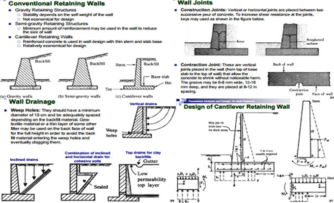
Dimensions of base from stress considerations:

The base width b concerning the retaining wall must be selected carefully in order that the ratio of length of the toe slab to the base width should be maintained in such a manner that the stress p1 at the toe should not surpass the safe bearing capacity of the soil.

The topics covered:

1. Design for conventional retaining wall
2. Retaining Wall Design – Proportioning
3. Earth Pressure on Retaining Wall
4. Equivalent Fluid Method
5. Retaining Walls with backfill slope of finite distance
6. Earth Pressure on Retaining Walls with backfill Slope of finite distance
7. Stability of retaining wall
8. Check Against Overturning
9. Check Against Sliding
10. Alternatives for improving FOS against sliding


Staircase Dimensions - How to Calculate Properly

~~~~~~~~~~~~~~~~~~~~~~~~~~
Published By
Rajib Dey
www.constructioncost.co
~~~~~~~~~~~~~~~~~~~~~~~~~~

Friday, February 22, 2019

LIMIT STATE DESIGN: (A Text-book of Reinforced Concrete Structures)

Dr. Ram Chandra, M.E. (Hons.), B.E., M.I.E., Ph.D (Roorkee), Professor of Structural Engineering has written an exclusive e-book alias LIMIT STATE DESIGN: (A Text-book of Reinforced Concrete Structures).

In this book, the author briefly explains each basic concept, elementary method, equation or theory of interest to the student of reinforced concrete design in simple manner. S.I. system of units and new code IS: 456-1978 are fully utilized in the text.

The book is specifically designed for degree, diploma and A.M.I.E. students in different branches of engineering. This book on ‘Limit State Design’ is based on the provisions of code IS: 456-1978. Both the topics of this subject, ‘Limit State of Collapse’ and ‘Limit State of Serviceability’ are clearly explained to design the reinforced concrete structures and the structural elements.

Given below, some exclusive features of the book :-

a. Each topic presented is described in detail.
b. This book is entirely composed of SI system of units and with adherence to the Indian Standard specifications (IS: 456-1978) all through the text.
c. The text of this subject is started, presented and explained in such a manner that is suitable for the students.
d. The different notations applied all through throughout this text book adhere to code of practice IS: 456-1978.

e. A number of design examples are provided in each chapter to demonstrate the theory and practice. Unsolved design problems are also provided in each chapter.
f. The diagrams clearly demonstrate the detailing of reinforcement.
g. This book abides by the current design practice.


To access the book online, click on the following link. www.amazon.in

LIMIT STATE DESIGN: (A Text-book of Reinforced Concrete Structures)

~~~~~~~~~~~~~~~~~~~~~~~~
Published By
Rajib Dey
www.constructioncost.co
~~~~~~~~~~~~~~~~~~~~~~~~


Saturday, October 6, 2018

Common types of walls found in construction

The following types of walls are generally found in building construction.

Types of Walls:
Load Bearing Walls - Precast Concrete Wall, Retaining Wall, Masonry Wall, Pre Panelized Load Bearing Metal Stud Walls, Engineering Brick Wall, Stone Wall


Non-Load Bearing Wall - Hollow Concrete Block, Facade Bricks, Hollow Bricks, Brick Walls, Cavity Walls, Shear Walls, Partition Walls, Panel Walls, Veneered Walls, Faced Walls.

Given below, the details of these walls.

Load Bearing Walls: Load bearing wall belongs to a structural component. It bears the weight of a house from the roof and upper floors and transmits the weight to the foundation. It provides support to the structural members like beams, slab and walls situated over floors. A wall that is situated directly over the beam is known as load bearing wall. The purpose of load bearing wall is to bear the vertical load. On contrary, if a wall doesn’t contain any walls, posts or other supports directly over it, it is prone to be a load-bearing wall.

Load bearing walls also bear their self weight. This wall is normally situated over one another on each floor. Load bearing walls are utilized as interior or exterior wall. This type of wall will often be perpendicular to floor joists or ridge. Concrete is a useful material to support these loads. The beams enter directly into the concrete foundation. Load bearing walls inside the house is likely to run the equivalent direction as the ridge.

Various types of load bearing walls:
Precast Concrete Wall, Retaining Wall, Masonry Wall, Pre Panelized Load Bearing Metal Stud Walls, Engineering Brick Wall, Stone Wall.


Non-Load Bearing Walls: Non-load bearing wall means a wall that doesn’t allow the structure to stand up and retain itself. It doesn’t deal with floor roof loads over. It is a framed structure. Normally, these belong to interior walls whose purpose is to separate the structure into rooms. They are constructed lighter.

The non-load bearing walls can be eliminated devoid of risking the safety of the building. Non-load bearing walls are recognized with the joists and rafters. They are not intended for gravitational support for the property. This type of wall is inexpensive. This wall is also known as “curtain wall”.

Types of Non-Load Bearing Wall:
Hollow Concrete Block, Facade Bricks, Hollow Bricks, Brick Walls


Cavity Walls: The cavity wall comprises of two individual withes which are formed with masonry. These two walls are called as internal leaf and external leaf. This wall is also called as a hollow wall. The purpose of these walls is to minimize their weights on the foundation. The walls function as good as sound insulation. Cavity wall offers superior thermal insulation as compared to any other solid wall since the space is completely filled with air and lessens heat circulation. They contain a heat flow rate that is 50 percent that of a solid wall. It is very cost-effective as compared to other solid walls. It has good fire resistance capacity. Cavity wall facilitates to get rid of noise.

Shear Walls: It stands for a framed wall. The prime objective of the wall is to withstand lateral forces which generate from the exterior walls, floor, and roofs to ground foundation. The shear wall is effective for large and high-rise buildings. The main ingredients of this wall are concrete or masonry. It contains a sound structural system to withstand earthquake. It offers stiffness in the direction. The construction and application are easy in shear walls. It is situated uniformly to minimize adverse effects of a twist.

Partition Walls: It is suitable for segregating spaces from buildings. The wall is hard and made of brick or stone. It is a framed construction. The partition wall is attached with the floor, ceiling, and walls. It has good strength to bear its own load. It defends against impact. It is durable and strong to support wall fixtures. Partition wall functions as a sound barrier and it has good resistance capacity against fire.

Panel Walls: It is a non-bearing wall among columns or pillars that are supported. The panel is set up with both nails and adhesive. The paneling design choices comprise of rustic, boards, frame. Paneling is done with hardwoods or inexpensive pine. Prior to set up panel walls, the space should be painted.

Veneered Walls: The material is retained through a veneered wall. The brick or stone are main ingredients of the veneered walls. The wall is only one wythe thick. It became the norm when insulation is necessary in the interior walls for building codes. It is light weighted. Less time is required for building up the veneered walls.

Faced Walls: It is a wall where masonry facing and backing are attached to make use of common action under load. The installation process is very simple.

Common types of walls found in construction

Read more

~~~~~~~~~~~~~~~~~~~~~~~~
Published By
Rajib Dey
www.constructioncost.co
~~~~~~~~~~~~~~~~~~~~~~~~

Friday, August 24, 2018

Some useful tips on proper bricklaying process

Bricklaying is treated as one of the most vital construction skills specifically when the structural walls are constructed.

In this useful construction article, you will learn the step-by-step methods to construct a garden wall. The steps involve setting out the footprint and maintaining level and square to blend the mortar, bedding the bricks and finishing joints efficiently.

Prior to start the project, find out the number of necessary bricks. Standard types are 215mm x 102.5mm x 65mm.

To obtain a perfect result, there should be 10mm mortar bed. Now, enter your brick size as 225mm x 102.5mm x 75mm for standard products.

The following equipments will be required for this purpose :-

1. Brick trowel
2. Old board
3. Tape measure
4. Spirit level
5. Brick/string line
6. Shovel

7. Club hammer
8. Bolster
9. Stiff brush


Step 1: As soon as the foundation is set properly, arrange the bricks at both ends of the wall where the pillars will be constructed. With the help of the string line, create a straight guideline at brick height among the two exterior bricks.

Step 2: Stack five shovels filled up with sand and one of cement on an old board. Turn shovel for being blended with a uniform color. Create a central hollow, pour in water and mix. Reiterate the steps unless a smooth, creamy texture is produced that’s wet but not excessively loose.

Step 3: Place a 1-2cm mortar bed along the string line. Start from one end, place the first brick and tap a little to ‘bed in’. ‘Butter up’ one end of the next brick with mortar and abut it to the first. Reiterate with string line as a guide.

Step 4: At the point where the pillars should be located, arrange a brick side-on to the end of the wall. While constructing the wall, each successive course of pillar bricks should be placed in the opposite direction.

Step 5: While constructing pillars, at specific courses, it is required to place half-bricks. To create a cut, arrange the brick on its side, trace the bolster at the split point and strike the head tightly by a club hammer. It should rupture neatly first time.

To get more details, go through the following link self-build.co.uk

Some useful tips on proper bricklaying process


~~~~~~~~~~~~~~~~~~~~~~~~
Published By
Rajib Dey
www.constructioncost.co
~~~~~~~~~~~~~~~~~~~~~~~~

Tuesday, August 7, 2018

Details of Cast in Situ Concrete Piles and their advantages

Cast In Situ belongs to a construction item or structural member similar to a beam or in this case a Pile that should be built up, assembled or poured at site instead of prefabrication in a factory. Normally, in cast in place or cast in situ construction, concrete is delivered from a batch plant to site where it is poured and compressed into the formwork that is fixed in required shape and dimensions at site.

Cast in situ or cast-in-place piles are cast in position inside the ground; generally in such type of piles, drilling of necessary diameter and depth into the ground is done with an auger drilling device or a drill bit.

There is a helical screw blade generally known as a “fighting blade” inside the device that functions as a screw conveyor to eliminate the drilled out material. Besides, auger drilling an old method known as percussion drilling is also applied for excavating the hole. Under this method, a heavy cutting or hammering bit affixed to a roper or cable is lowered in the open hole or inside a temporary casing.

After entering deep into the ground, a temporary steel casing is lowered in the borehole to safeguard loose soil from dropping in the borehole.

The verticality of the casing should be examined precisely prior to start. Once the optimal depth is attained, the reinforcement cage with vertical rebars and stiffeners is lowered within the borehole, and the upper part is hanged at the top. The concreting is generally performed with Tremie method of concrete piling.

There are normally 6 types of cast in situ piles as below:-

1. Simplex Pile, 2. Franki Pile, 3. Vibro Pile, 4. Vibro Expanded Pile, 5. Raymond Pile, 6. Mac Arthur Pedestal Pipe

Benefits of Cast In Situ Concrete Piles: The cast in situ piles are set up with pre-excavation and reduce the vibration because of driving as in case of driven piles.

In housing area, sound pollution may occur if the piles are entered by hammering. To get rid of this issue, situ piling is suitable in such areas.

For water logged area, cast in situ piling with permanent casing is very effective.

The skin friction resistance with the ground is fully used in cast in situ piles throughout the design phases that is not recommended in case of driven piles where only the end bearing is applied.

Normally, there is no need of any foreign materials and tools and the original equipments and materials will meet the requirements of a project, as a result the cast-in-situ piles become as a cost-effective and adjustable type of pile foundation.

Precast piles should be designed to satisfy the handling and driving stresses thus enhancing the essential reinforcement that does not happen in the case of cast in situ piles and therefore, the amount of necessary reinforcement is minimized.

Cast in situ piles are attached over the ground with a pile cap that applies a monolithic approach. The top ground is excavated up to pile cut off level from where the slushy low quality concrete is eliminated with hand hilty to retain developed rebars into the pile cap.

Because of this monolithic connection, cast in situ pile provides good resistance against the earthquake and wind forces.

As soon as the piles are casted, no maintenance is required.

Since the materials and machinery applied are obtained from the local community, local contractors can perform the job and not any skilled labor is required for cast in situ piles.

No serious consideration should be provided for joints in cast in situ piles with regards to precast driven piles.

Details of Cast in Situ Concrete Piles and their advantages

Read more

~~~~~~~~~~~~~~~~~~~~~~~~
Published By
Rajib Dey
www.constructioncost.co
~~~~~~~~~~~~~~~~~~~~~~~~

Thursday, August 2, 2018

How to develop strong brick veneer cavity walls

Brick veneer cavity walls are mostly recognized product which can be used at the exterior of different types of buildings. With its conventional, rugged aesthetic and tested performance, bricks become a perfect choice for commercial, institution, and multifamily residential structures.

While designing, detailing, and constructing a brick wall assembly, considerations should be given on various factors. Given below, some useful tips to maintain moisture control, thermal performance, integrity, and durability of brick walls.

Never skimp on flashing materials within the cavity. Conventional materials like copper, lead-coated copper, stainless steel are very expensive but they are considered as the most long-lasting and trustworthy options.

Plan for thermal expansion/contraction of brick and concrete. Brick assembles frequently integrate brick and concrete components, both of which are extended and compacted at various rates and in diverse conditions. Due to this detailing becomes complicated for horizontal and vertical expansion joints, shelf angles, and modifiable veneer anchors.

Choose the feeble mortar for the job. If the mortar is extremely rigid, adjoining bricks can’t be moved and result in producing cracks and spalls.

Arrange minimum one inch of air space behind brick veneer. This void space operates as the drainage cavity where water is headed downward to the flashing and weeps and out of the brick veneer. If open weeps are utilized, this air space also allows to discharge the cavity, facilitating the interior components to get dried instantly.

Get clear ideas on vapor flow direction, and detail accordingly. For normal buildings, the direction of water vapor flow will differ by season and often on every day, based on the climate.

To get more details, go through the following link www.bdcuniversity.com

How to develop strong brick veneer cavity walls


~~~~~~~~~~~~~~~~~~~~~~~~
Published By
Rajib Dey
www.constructioncost.co
~~~~~~~~~~~~~~~~~~~~~~~~

Tuesday, June 19, 2018

Some useful tips for reinforcement detailing

Given below, some useful tips for reinforcement detailing :-

Create drawings perfectly. Try to mark every bar and demonstrate its shape for transparency.

Cross section of retaining wall that falls quickly as soon as soil backfill is arranged since ¼” dia is used instead of 1 ¼” dia. Errors happen as exact rebar dia is covered with a dimension line.

If required, generate bar bending schedule.

Denote perfect clear cover, nominal cover or effective cover to reinforcement.

Settle detailed location of opening/hole and provide sufficient information for reinforcement around the openings.

Utilize the size of bars and spirals which are easily accessible. For a single structural member, there should limited numbers of various sizes of bars.

The grade of the steel should be mentioned properly in the drawing. Deformed bars should not contain hooks at their ends.

The enlarge details at corner, intersections of walls, beams and column joint should be demonstrated at identical situations. There should not be congestion of bars at points where members overlap and ensure that all reinforcements are placed perfectly.

For bundled bars, lapped splice of bundled bars should be formed by connecting one bar at once; such separate splices inside the bundle should be staggered.

Ensure that the hooked and bent up bars are arranged and there is sufficient protection for concrete.

Specify all expansion, construction and contraction joints on plans and provide details for such joints.

The position of construction joints should be at the point of minimum shear roughly at mid or adjacent to the mid points. It should be created vertically instead of a sloped manner.

Article Source: onlinecivilforum.com

Some useful tips for reinforcement detailing

~~~~~~~~~~~~~~~~~~~~~~~~
Published By
Rajib Dey
www.constructioncost.co
~~~~~~~~~~~~~~~~~~~~~~~~

Friday, June 15, 2018

RCC Column Design – An exclusive mobile based app for civil and structural engineers

RCC Column Design is an exclusive app for civil and structural engineers. This app is available in google play store. It can only work in windows platform.


The app is very user-friendly. There are several fields in the app which range from Factored Axial Load (kN), Length (mm), Width (mm), Concrete Strength (M15, M20 and M25), Steel Strength (HYSD 415, HYSD 500).
Just enter the values in these fields and click on calculate button to get the desired values.
This app is designed on the basis of the Limit State Method with adherence to Indian standard code IS 456:2000. This app takes into account the axial load on a column to recommend a secure design depending on input of column size, concrete strength and steel strength. The app is also very useful for Uniaxial and biaxial bendings.
This app can design a rectangular slender RCC column that contains standard height. It works out necessary reinforcement for a specified axial load for the assumed inputs.
This app is developed for educational purposes only. The answers should be double checked manually.
To download the app, click on the following link play.google.com
RCC Column Design – An exclusive mobile based app for civil and structural engineers


~~~~~~~~~~~~~~~~~~~~~~~~
Published By
Rajib Dey
www.constructioncost.co
~~~~~~~~~~~~~~~~~~~~~~~~

Thursday, March 22, 2018

How to work the volume of concrete in a retaining wall

This construction video will provide some useful tips on computing the volume of concrete for retaining wall.

Retaining wall is defined as a rigid wall that is designed and constructed to withstand lateral pressure of liquid, earth filling, sand or other coarse materials which it is holding back.

Suppose, a retaining wall is segregated into two sections, section A is taken as base slab and section B is taken as the stem of retaining wall.

Therefore, the volume of retaining wall is determined with the following formula :-

Volume of retaining wall = Volume of base slab + Volume of Stem

Volume of base slab = length x breadth x height

= 10 x 3 x 0.2 (after converting 200 mm to meter) = 6m3

As the stem is a trapezoid, the following formula is used to calculate it’s volume :-

Volume of stem = [{a+b)/2} x h] x l

After putting the values, we get :-

= [{(0.5 + 0.2)/2} x 3] x 10 = 21m3

Therefore, total volume of retaining wall = 6 + 21 = 27m3

Therefore, the volume of concrete for the retaining wall = 27m3

If the retaining wall is segregated into three parts like part A, part B and part C. Part A is taken as the base slab, part B is taken as the stem and part C is taken as the counterfort of the retaining wall.

Therefore, the volume of retaining wall = Volume of base slab + volume of stem + volume of counterfort

= Volume of A + Volume of B + Volume of C

To learn the remaining calculation process, go through the following video tutorial.
Video Source: Nice engineering


~~~~~~~~~~~~~~~~~~~~~~~~
Published By
Rajib Dey
www.constructioncost.co
~~~~~~~~~~~~~~~~~~~~~~~~

Monday, February 5, 2018

Why RC Structural Slabs and Beams are provided in plinth level

Given below, the detailed information on the importance of arranging RC structural slabs and beams at plinth level (GF-Finished Floor Level).

Wherever low/poor bearing capacity soils met with, the Architects and also certain Builders think and believe that If the bearing strength of soils become weak or low, RC Structural slabs & Beams may be arranged at plinth level (GF-Finished floor level) with the purpose of preventing settlement of foundation and subsequent development of cracks in walls.

By applying your own experience and expertise in foundation structure, it is possible to have clear idea on the behavior of weak bearing soil if loaded heavily. The foundation cost is raised by 50% with the inclusion of the cost of setting up RC Structural Slabs & Beams.

But the provision of RC structural slabs and Beams at plinth level may not be considered as useful solution to get rid of foundation settlement and subsequent cracks. Rather it will be treated as extra expenses that is incurred on the construction of structure.

It is recommended to apply the following measures to resist the settlement of foundation systems and wall cracks efficiently.

The foundation soil at a depth of 00 m to 2.70m (if it belongs to a weak bearing soil like soft/medium clay) should be artificially reinforced with Geogrids/Geotex layers supported with Quarry dust:Gravel Mix 1:3 or cement.

Quarry dust 1:10 mix in 4 or 5 layers of 200 mm thick will enhance the SBC of soil at 2.00m/1.80m level to 200kN/m2 from 100kN/m2.

Arrange an extra layer of Geogrid/Geotex over and then apply the PCC 1:5:10 for 100 mm. Over which the foundation system should be provided as designed-combined strip Raft/combined/isolated footings as per situation. Inspite, under reamed piles with pile cap may be arranged directly.

To get more details, go through the following link onlinecivilforum.com
Why RC Structural Slabs and Beams are provided in plinth level

~~~~~~~~~~~~~~~~~~~~~~~~
Published By
Rajib Dey
www.constructioncost.co
~~~~~~~~~~~~~~~~~~~~~~~~

Tuesday, August 1, 2017

Step-by-step guidelines to develop a concrete block wall

A concrete block wall is formed with standard size concrete blocks. The standard size belongs to 8 inches. The sizes of the blocks may differentiate based on the design parameters and standards fixed by an engineer for the concrete structure.
A structure that is build up with concrete block is susceptible to concrete corrosion. Therefore, blocks are pre-coated to resist corrosion in the concrete block wall structure.
This construction video tutorial briefly shows how to construct a 20 feet long block wall from scratch with your own effort.
The block wall is built up on the basis of the following specification :-
Grade N units should be used for concrete blocks.
F’C (the specified compressive strength for concrete) should be 2500 psi for footing.
Reinforcing Steel should have been A615 Grade 40 or 60.
Fill all cells having steel with grout along with bond beam.
The wall should have been plumb and all block courses should be level.
Reinforcing steel splices should be at least 24”.

The first course should be arranged in fresh concrete for footing.
No of wall or fence should be permissible inside 36” of a fire hydrant and no wall, fence or foundation should be permissible inside 12” of a water meter.

Makin proper plan to adjust the height, location and design of the wall on the basis of the zone, location on the community design standards. Planning should be sanctioned before any permit is issued.

Read Continue

~~~~~~~~~~~~~~~~~~~~~~~~
Published By
Rajib Dey
www.constructioncost.co

~~~~~~~~~~~~~~~~~~~~~~~~

Tuesday, September 6, 2016

A Useful Demonstration On Reinforcing Detailing Of R.C.C Members

A design engineer should take liabilities for ensuring the structural security of the design, details, checking shop drawing.

Detailing is also a vital part of any construction as perfect detailing of engineering designs is required in the planning and engineering phase for proper accomplishment as well as safety of the structures. Defective connections or detailing may lead to collapsing.

Detailing plays an important role for the steel structures as well as for the RCC members as it remains the translation of all the mathematical expression’s and equation’s results.

For commonly used RCC members, the detailing can be segregated for Slabs-with or without openings.(Rectangular,circular,non-rectangular-pyramid slab,triangular etc) balcony slab, loft slab, corner slab etc

Beams – With or without openigs.(Shallow & deep beams)
Columns – (Rectangular,l-shape,t-shape, circular,octagonal,cross shape etc)
Foundations.

Detailing for gravity loads differs with the lateral loads particularly for the SEISMIC FORCES.

A different types of detailing is essential for the Rehabilitation and strengthening of damaged structures.

For perfect DETAILING, the following processes are necessary:-

DO’S-GENERAL
Make drawings perfectly and label each bar & show its shape for accuracy

Cross section of retaining wall is collapsed instantaneously due to placing of soil backfill that contains ¼” dia instead of 1-1/4” dia. The error may happen as proper rebar dia was covered with a dimension line.

  • If required, generate bar-bending schedule.
  • Specify perfect cover-clear cover, nominal cover or effective cover to reinforcement.
  • Select detailed location of opening/hole and provide sufficient details for reinforcements just about the openings.
  • Apply the bars and spirals which are generally available. For a single structural member, the number of various sizes of the bars should be lowest.
  • There should be clear information in the drawing for the grade of the steel.
  • Deformed bars should contain at their ends.
  • Show distended details at corners, intersections of walls, beams and column joint and at parallel situations.
  • Blockage of bars should be avoided at points where members intersect and make certain that all rein. Can be properly placed.
  • In the case of bundled bars, lapped splice of bundled bars shall be made by splicing one bar at a time; such individual splices within the bundle shall be staggered.
  • Make sure that hooked and bent up bars can be placed and have adequate concrete protection.
  • Indicate all expansion, construction and contraction joints on plans and provide details for such joints.
  • The placing of construction joints should remain at the point of minimum shear roughly at mid or near the mid points. It is developed vertically and not in a sloped manner.

To read the complete article, visit www.engineeringcivil.com

A useful demonstration on Reinforcing Detailing Of R.C.C Members

~~~~~~~~~~~~~~~~~~~~~
Published By
Rajib Dey
~~~~~~~~~~~~~~~~~~~~~

Tuesday, June 28, 2016

Reinforcing Of Shear Wall

The boundary elements, whether regular or hidden, are reinforced based on the rules which are assigned to columns.

For reinforcing of the wall body, there are two parallel grates (known as curtains) one at each face. They are retained collectively through an ‘S’-shaped vertical bar. The vertical and horizontal grate rebars should contain a diameter at least identical to Ø8 .The reinforcement with “S” shape must be higher or equivalent to 4Φ8/m2

To avoid cracked surfaces e.g. in pool sides, narrow spaced grates should be applied having the lower possible rebar diameter.

To avoid cracked surfaces e.g. in pool sides, narrow spaced grates should be applied having the lower possible rebar diameter.

The ‘S’- shaped reinforcement

The ‘S’-shaped bar offers anti-buckling restraint to the longitudinal reinforcement. Besides, it makes sure that the vertical and the horizontal rebars will progress work jointly regardless of a potential concrete spalling that may occur due to an strong earthquake.

The ‘S’-shaped link is developed with one closed corner at an angle similar to 180°, or 135° and the other corner bent at an angle equivalent to 90°. This is crucial for positioning it without any difficulty. Once it is applied, the second corner must be also bent at an angle at least equivalent to 135°.

It is acceptable to apply soft steel to have the ability to bent the ‘S’-shaped reinforcement manually.

If the vertical rebars are positoned in an interior layer, then the ‘S’-shaped link must detain the horizontal rebars to the region that they bisect with the vertical ones or get around both horizontal and vertical rebars simultaneously.

On the other hand, in an rectangular shear wall, the reinforcement of the boundary column and the distribution rebars of the wall’s body is carried out as two ‘Γ’ shaped parts. Folded mesh is applied to develop the ‘Γ’ shaped parts.


Reinforcing of Shear Wall
Image Courtesy - debug.pi.gr
~~~~~~~~~~~~~~~~~~~~~
Published By
Rajib Dey
~~~~~~~~~~~~~~~~~~~~~

Tuesday, May 3, 2016

Categories, Design And Modes Of Failure Of Retaining Walls

Retaining wall is described as a fairly hard wall. It is constructed to give support to the soil mass horizontally to hold the soil at various levels on the two sides.

The following topics are covered in this construction article :-
• Types
• Design
• Modes of Failure

Types of retaining wall:
Usually the retaining walls are categorized as follow :-
Gravity Retaining Wall: Here weight is the key factors for these walls to maintain durability. In general, the walls are developed with plain concrete or masonry. For the structures having long height, these walls may be quite expensive.

Semi-gravity Retaining Wall: The section size regarding a gravity retaining wall is decreased with the placement of the fewer amount of adjacent to the back face. Such walls can be termed as semi-gravity walls.

Cantilever Retaining Wall: The Cantilever retaining walls are mainly developed with reinforced cement concrete. The wall comprises of a lean stem together with a base slab cast monolithically. For the construction that contains a height of 6 to 8 m, this type of wall is cost-effective.

Counterfort Retaining Wall: In Counterfort Retaining walls, there are lean vertical slabs alias counterforts which are positioned over the vertical steam recurrently. The counterforts join the vertical stem by the base slab. Hence, the vertical stem and the base slab extend amid counterforts. Here the counterforts are used to reduce the shear force and bending moments in the vertical stem and the base slab. The structures which contain a height over 6 to 8 m, the counterfort retaining walls are economical.

Guidelines for designing retaining walls: Before developing the realistic design, the soil parameters which can impact the earth pressure and the bearing capacity of the soil, must be analyzed properly. The soil parameters contain the unit weight of the soil, the angle of shearing resistance, the cohesion intercept and the angle of wall friction. The soil parameters are liable for detecting the lateral earth pressures and the bearing capacity of the soil. As soon as the earth pressures are detected, the retaining walls should be verified completely to find out the strength toward sliding, overturning, bearing capacity failure & tension.

Other modes of failure of retaining walls
Besides, three types of failures like sliding, overturning and bearing failure, the following two modes are also liable for collapsing of a retaining wall in case the soil below is feeble.

Shallow Shear Failure: This type of failure takes place along a cylindrical passing with the heel of the retaining wall owing to the extreme shear stresses along the cylindrical surface inside the soil mass. Usually the cause for safety alongside horizontal sliding is reduced contrary to the shallow shear failure. Due to this, if the factor of safety alongside sliding exceeds by 1.5, shallow shear failure will not occur.

Deep shear failure: It happens along a cylindrical surface, if there exists a feeble layer of soil below the wall a depth regarding 1.5 times the height of the wall. The trial and error processes are applied to ascertain the critical failure surface.


Categories, design and modes of failure of retaining walls


~~~~~~~~~~~~~~~~~~~~~
Published By
Rajib Dey
~~~~~~~~~~~~~~~~~~~~~