adsense analytic

Showing posts with label Building Cost Estimating. Show all posts

Friday, November 16, 2018

How to calculate mason, labor for brick masonry construction with help of thumb rule

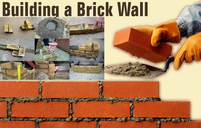
In this construction video tutorial, you will learn how to compute the mason as well as labor toward a 1st class brick masonry construction with the help of thumb rule.

A thumb rule refers to a principle having extensive application that is not projected to be exactly perfect or authentic for each situation. This method can be easily applied for making approx calculation or recollecting some value, or for making some determination.

It should be noted that the quantity of required labor will be gradually increased from ground floor to first floor to second floor etc.

Thumb rule is a constant value that is taken from the earlier construction work i.e. how much volume is covered by the labors employed in earlier projects. All the volumes are summed up to find out the average volume.

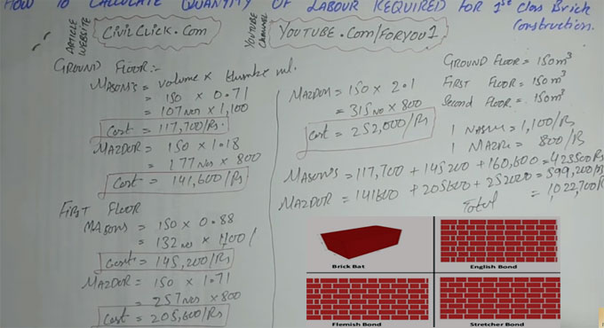
In ground floor, first floor and second floor, the volume of total area is taken as 150 m3

Ground floor :-

Mason = Volume x thumb rule (for mason) = 150 x 0.71 = 107 numbers
Now, suppose the charge for one mason = 1100 rupees
So, the cost for mason will be 107 x 1100 = 117, 700 rupees


Labor = 150 x 1.18 (thumb rule for labor) = 177 numbers
Suppose, one labor charge 800 rupees
Therefore, cost of labor = 177 x 800 = 141,600 rupees


Similar process should be followed for 1st floor and 2nd floor. Here, the value of thumb rule will be increased as the steps are increase.

To learn the calculation for 1st and 2nd floor, watch the following construction video tutorial.

How to calculate mason, labor for brick masonry construction with help of thumb rule

Read more
~~~~~~~~~~~~~~~~~~~~~~~~
Published By
Rajib Dey
www.constructioncost.co
~~~~~~~~~~~~~~~~~~~~~~~~

Friday, August 24, 2018

Some useful tips on proper bricklaying process

Bricklaying is treated as one of the most vital construction skills specifically when the structural walls are constructed.

In this useful construction article, you will learn the step-by-step methods to construct a garden wall. The steps involve setting out the footprint and maintaining level and square to blend the mortar, bedding the bricks and finishing joints efficiently.

Prior to start the project, find out the number of necessary bricks. Standard types are 215mm x 102.5mm x 65mm.

To obtain a perfect result, there should be 10mm mortar bed. Now, enter your brick size as 225mm x 102.5mm x 75mm for standard products.

The following equipments will be required for this purpose :-

1. Brick trowel
2. Old board
3. Tape measure
4. Spirit level
5. Brick/string line
6. Shovel

7. Club hammer
8. Bolster
9. Stiff brush


Step 1: As soon as the foundation is set properly, arrange the bricks at both ends of the wall where the pillars will be constructed. With the help of the string line, create a straight guideline at brick height among the two exterior bricks.

Step 2: Stack five shovels filled up with sand and one of cement on an old board. Turn shovel for being blended with a uniform color. Create a central hollow, pour in water and mix. Reiterate the steps unless a smooth, creamy texture is produced that’s wet but not excessively loose.

Step 3: Place a 1-2cm mortar bed along the string line. Start from one end, place the first brick and tap a little to ‘bed in’. ‘Butter up’ one end of the next brick with mortar and abut it to the first. Reiterate with string line as a guide.

Step 4: At the point where the pillars should be located, arrange a brick side-on to the end of the wall. While constructing the wall, each successive course of pillar bricks should be placed in the opposite direction.

Step 5: While constructing pillars, at specific courses, it is required to place half-bricks. To create a cut, arrange the brick on its side, trace the bolster at the split point and strike the head tightly by a club hammer. It should rupture neatly first time.

To get more details, go through the following link self-build.co.uk

Some useful tips on proper bricklaying process


~~~~~~~~~~~~~~~~~~~~~~~~
Published By
Rajib Dey
www.constructioncost.co
~~~~~~~~~~~~~~~~~~~~~~~~

Tuesday, August 21, 2018

Some crucial information about concrete mix design

Mix Design refers to the method of choosing perfect materials of concrete and finding out their proportionate ratios with the purpose of developing concrete with minimum specific strength and stability as reasonable as possible.

To form concrete maintaining desired strength and properties, choosing of components and their quantity should be determined and it is defined as concrete mix design.

The site engineer should provide following information at the time of delivering material for mix design to the mix design laboratory :-

A) Grade of concrete (the characteristic strength)
B) Necessary workability regarding slump
C) Other properties (if necessary)


Retardation of initial set (to get rid of cold joints for longer leads or ready mix concrete)

Slump retention (for ready mix concrete)

Pumpability (for ready mix concrete)

Expedition of strength (in case of precast members or where initial deshuttering is required)

Flexural strength (generally necessary concrete pavements)

Determine whether condition of exposure to concrete is mild, moderately severe or very severe. Exact analysis of soil should be made to determine existence of sulphates & chlorides for any doubt.

The degree of control at construction site is based on the following factors :-

Batching – Weigh batching/volume batching

Type of aggregates – Whether the type of aggregate will be mix graded or 10 mm, 20 mm aggregates should be utilized independently.

Testing of concrete – Whether casting & testing of concrete cubes should be performed at construction site on regular basis.

Source of aggregate – Whether sources of sand and aggregate are standard or should be altered regularly.

Supervision – Whether skilled staffs are there to superintendent concreting work and make require changes like rectification of moisture in sand and alteration in material properties.

Site laboratory – Whether the site will contain required laboratory tools like sieves, weighing balance etc. for the verification of material properties.

Some crucial information about concrete mix design

Read more

~~~~~~~~~~~~~~~~~~~~~~~~
Published By
Rajib Dey
www.constructioncost.co
~~~~~~~~~~~~~~~~~~~~~~~~

Monday, August 20, 2018

How to check the quality of cement at the construction site

The quality of cement should be examined properly prior to utilize it in concrete, plastering or any other purpose at construction work site.

For quality checking, initial inspection is very crucial. It may not always feasible to check all the engineering qualities required for utilizing cement on site but the quality of cement can be checked roughly through some recognized field test in the construction site. But the other crucial tests should be performed in laboratories.

Field Tests to verify the quality of Cement

1. Date of Packing Cement: Before purchasing cement, make proper investigation regarding the date of manufacture provided on the cement bags. It is very crucial since the strength of cement is decreased with age.

2. Colour: The color of cement should be consistent. Usually, the colour of cement remains grey with a light greenish shade. The colour of cement symbolizes surplus lime or clay and the degree of burning.

3. Rubbing: Take a pinch of cement among fingers and rub it, It should appear smooth at the time of rubbing. If it feels rough, there is adulteration with sand.

4. Temperature Test of Cement: Push your hand into the cement bag and it should feel cool. It means that there is no hydration reaction in the bag.

5. Float Test: Provide a small quantity of cement in a bucket of water. It should submerge and should not float on the surface.

6. Smell Test: Select a bit of cement and smell it. If there is excessive pounded clay and silt as an adulterant in the cement, the paste will provide an earthy smell.

7. Existence of Lumps: Open the bag and check that no lumps exist in the bag. It will make sure that no setting has occured.

8. Shape Test: Select 100g of cement and make a stiff paste. Make a cake with sharp edges and placed on the glass plate. Submerge this plate in water. Verify that the shape should remain as it is at the time of settling. It should have the capability for being set and obtained strength. Cement has the capacity of being set under water also and for this reason it is known as ‘Hydraulic Cement’.

9. Strength of Cement Test: A block of cement 25 mm*25 mm and 200 mm long is arranged and absorbed for 7 days in water. It is then set on supports 15000 mm apart and it is loaded with a weight of 340 N. The block should not demonstrate any sign of failure.

How to check the quality of cement at the construction site

Read more

~~~~~~~~~~~~~~~~~~~~~~~~
Published By
Rajib Dey
www.constructioncost.co
~~~~~~~~~~~~~~~~~~~~~~~~

Thursday, August 16, 2018

Some useful tips on quality control and safety in construction

A structure may collapse or becomes defective because of substandard quality control. Re-construction becomes necessary and facility operations get damaged due to even small defects.

The construction cost is raised and construction delays occur. Also, there may be personal injuries or fatalities because of collapsing of structure.

Accidents throughout the construction process can also lead to personal injuries and greater costs. Indirect costs related to insurance, inspection and regulation are also raised significantly because of these inflated direct costs.

A knowledgeable project manager is liable for completing the construction work in scheduled time and he ensures that no major accidents take place on the project.

As with cost control, the most vital decisions concerning the quality of a completed facility are taken throughout the design and planning phases in spite of construction.

It is throughout these initial phases that component configurations, material specifications and functional performance are settled efficiently. Quality control throughout construction mainly comprises of insuring conformance to these original design and planning decisions.

Besides, unanticipated circumstances, inaccurate design decisions or modifications required by an owner in the facility function will involve reassessment of design decisions throughout the course of construction. These modifications are caused by the concern for quality, they characterize occasions for re-design with all the accompanying objectives and hindrances.

Some designs are based on the reasonable and perfect decision making throughout the construction process itself. As for instance, some tunneling methods will allow taking decisions concerning the amount of shoring essential at various locations on the basis of inspection of soil conditions throughout the tunneling process. Since such decisions are taken on the basis of superior information about actual site conditions, the facility design may be economical as a result.

By giving emphasis on conformance as the measure of quality throughout the construction process, the specification of quality requirements in the design and contract documentation becomes significantly vital. Quality requirements should be concise and valid, so that all the project stakeholders can recognize the requirements for conformance.

Safety during the construction project is also a great concern for the decisions taken throughout the planning and design phase. Some designs or construction plans are indigenously critical and hazardous for execution, whereas other equivalent plans may significantly lessen the chance of accidents. As for instance, clear segregation of traffic from construction zones throughout roadway rehabilitation can considerably minimize the chance of accidental collisions. Besides, safety is mostly based on education, vigilance and cooperation all through the construction process. Proper alert should be sent to the workers repeatedly to get rid of accidents and refrain from taking nonessential risks.

Some useful tips on quality control and safety in construction

Read Continue
~~~~~~~~~~~~~~~~~~~~~~~~
Published By
Rajib Dey
www.constructioncost.co
~~~~~~~~~~~~~~~~~~~~~~~~

Friday, July 27, 2018

Some useful tips for proper foundation design

The foundations should remain as shallow as possible, in conformity with climatic effects and strength of the surface soil; specifically in waterlogged ground.

For large underground structure, shoring work design details should be perfectly defined. The structure should be considerably inflexible.

Foundation design should be inexpensive & supported with updated technology to curtail piling cost. Ground treatment work should be carried on consequently.

Designers should be well versed with the presumptions provided in design, the changeability of ground conditions, the occasional in-applicability of refined soil analyses and the feasibiity of construction.

Soil investigation report should be prepared by an experienced Geo-technical Engineer. The assessment report should comprise of all essential data.

The construction on ground properties provides various impacts like vibration from piling, damage of ground due to excavation in unfavorable weather conditions, elimination of overburden, periodical change in the water-table, compaction of the ground by construction plant.
Impact of unstable shape, length and inflexibility of the foundation, and the requirement for movement and settlement joints.
After-effects on completed foundations concerning sulfate attack on concrete, ground movements because of frost heave, shrinkable clay, and the impacts of trees; also alterations in local environment, e.g. new construction, re-routing of heavy traffic, installation of plant in adjacent factories creating impact and vibration.
Fast but expensive construction may be more economic than low-cost but slow construction to clients needing quick return on capital investment.
Impact of new foundation loading on current adjacent structures.
Some useful tips for proper foundation design

~~~~~~~~~~~~~~~~~~~~~~~~
Published By
Rajib Dey
www.constructioncost.co
~~~~~~~~~~~~~~~~~~~~~~~~

Thursday, July 26, 2018

How impact of trench excavation on adjoining building is measured with rule of thumb

The adjoining buildings are greatly impacted with trench excavation and lead to settlement. This construction article briefly explains how to gauge the impact of trench excavation on adjoining buildings with rule of thumb.
The two factors are mainly responsible for impact of trench excavation on the buildings:
• Soil relaxation because of excavation
• Diminishing of groundwater owning to excavation
Soil relaxation because of excavation
When a trench is excavated adjoining a building, soil relaxation and subsequent settlement of the building is increased.
So, there should be sufficient support for the trench to resist soil relaxation. On the other hand, excavate the trench far from the foundation but it will not be a legitimate option always.
Besides, a rule of thumb is applied to examine whether the trench excavation affects the nearby building or not. Draw a line with 2H:1V from the bottom of the foundation. If the trench remains within this line, then engineer shall look forward to soil relaxation and eventual settlement of building foundation.
Lastly, if the soil at job site comprises of loose sandy soil, then draw the line with 3H:1V instead of 2H:1V.
Diminishing of Groundwater due to excavation: Generally, groundwater proceeds and seeps into the excavation from the adjacent areas of the trench. It will reduce the level of ground water in the trench vicinity area. Effective stresses are raised due to groundwater lowering and accordingly the foundation experiences settlement.
Last but not least, diminishing ground water raises effective stress in clay layer and higher effective stress leads to foundation settlement.
How impact of trench excavation on adjoining building is measured with rule of thumb

~~~~~~~~~~~~~~~~~~~~~~~~
Published By
Rajib Dey
www.constructioncost.co
~~~~~~~~~~~~~~~~~~~~~~~~

Monday, July 23, 2018

Setting out survey process – Definition and various benefits

Setting survey process is applied to set out the exact position of a projected structure inside the legal boundaries of a plot of land.

The objective of setting out is to set out perfect position & levels of building lines and road alignments for a projected structure as per construction plans by applying different techniques and instruments.

This type of survey is very vital while going to set up any type of construction work.

Generally, a set-out survey comprises of the process for transforming a building design onto the land itself in order that the builders can abide by the process throughout construction. Throughout the process, major points are set up and markers are applied for the progression of the building process and maintain perfectness.

For large scale projects like high rise buildings and developments, multiple set-out surveys are required as the construction advances. This type of survey is mainly undertaken for the earthworks, roads, car parks, sewerage, water and the actual buildings themselves.

Methods of Setting Out Survey


1. Setting out buildings by coordinates
2. Setting out with theodolite and level
3. Examining verticality
4. Setting out and alignment in steel framed buildings
5. Alignment and verticality in form work
6. Control and computation for route surveying
Setting Out Building by Coordinates
A building is set out by adopting referencing from an already established baseline. An asymmetrical building or a building with complicated geometry can also be established by applying the equivalent process. For each corner of the building, a grid line is set up from the baseline.
Examine Verticality - The verticality of points in a building is examined with the following surveying instruments:
1. Plumb Bob (For buildings less than 20m in height)
2. Optical Plummet (A transparent plastic sheet is used as a target for checking verticality of tall buildings)
3. Theodolite
Setting out Survey works also contains the following :-
Calculations and setting out Methods for:
1. Simple Circular Curves
2. Compound Curves
3. Reverse curves
4. Transition curves
5. Vertical curves
To get more details, go through the following video tutorial
Video Source: Finchley College

~~~~~~~~~~~~~~~~~~~~~~~~
Published By
Rajib Dey
www.constructioncost.co
~~~~~~~~~~~~~~~~~~~~~~~~

Friday, June 15, 2018

RCC Column Design – An exclusive mobile based app for civil and structural engineers

RCC Column Design is an exclusive app for civil and structural engineers. This app is available in google play store. It can only work in windows platform.


The app is very user-friendly. There are several fields in the app which range from Factored Axial Load (kN), Length (mm), Width (mm), Concrete Strength (M15, M20 and M25), Steel Strength (HYSD 415, HYSD 500).
Just enter the values in these fields and click on calculate button to get the desired values.
This app is designed on the basis of the Limit State Method with adherence to Indian standard code IS 456:2000. This app takes into account the axial load on a column to recommend a secure design depending on input of column size, concrete strength and steel strength. The app is also very useful for Uniaxial and biaxial bendings.
This app can design a rectangular slender RCC column that contains standard height. It works out necessary reinforcement for a specified axial load for the assumed inputs.
This app is developed for educational purposes only. The answers should be double checked manually.
To download the app, click on the following link play.google.com
RCC Column Design – An exclusive mobile based app for civil and structural engineers


~~~~~~~~~~~~~~~~~~~~~~~~
Published By
Rajib Dey
www.constructioncost.co
~~~~~~~~~~~~~~~~~~~~~~~~

Monday, June 11, 2018

Some crucial factors a civil engineer should follow

This construction video tutorial sifts through some vital factors which should be abided by a civil engineer to apply them in the jobsite.
The factors are discussed in below :-
Compressive strength of bricks should be 3.5 N/mm2
Water immersion of bricks should not surpass 15%
Free fall of concrete is permissible up to 1.50 m
Lowest thickness of slab is 125 mm
Longitudinal reinforcement should not be under 0.8% and over 6% of gross C/S
Lowest bars required for square column is 4 Nos and for circular column is 6 Nos
If the bars contain diameter over 36 mm., lapping is not permissible
Compressive strength of bricks is 3.5 N/mm2
Earthwork excavation toward basement over 3 m should remain in stepped form
Cement should be preserved in dry places on a raised platform roughly 200 mm
Electrical conduits should not be set in column
For more information, watch the following construction video.

Read more

~~~~~~~~~~~~~~~~~~~~~~~~
Published By
Rajib Dey
www.constructioncost.co
~~~~~~~~~~~~~~~~~~~~~~~~

Thursday, May 31, 2018

How to estimate cement bags in 1 cubic meter

Suppose the proportion of nominal mix is 1:2:4 (one part cement, 2 part sand and 4 part aggregate)

Wastage of cement is taken as 2%
Output of mix is provided as 67%.


For 1 cum output, the requirement of dry mix is 1/0.67 = 1.49 say 1.50 cum.
After including the wastage (2%), the output will be (1.50 + 0.02) = 1.52 cum.
Volume of cement = (cement/cement+sand+aggregate) × Total material


= (1/1+2+4) × 1.52
=0.2171 cum
The density of cement is 1440 kg/cum and
Weight of 1 bag cement = 50 kg.


So, volume of 1 bag cement = 50/1440
=0.0347 cum.
No. of cement bags essential in 1 cubic meter = 0.2171/0.0347
= 6.25 bags.
The above formula can be utilized for measuring cement for other nominal mixes.


To get more details, watch the following video tutorial.


Read more

~~~~~~~~~~~~~~~~~~~~~~~~
Published By
Rajib Dey
www.constructioncost.co
~~~~~~~~~~~~~~~~~~~~~~~~

Monday, April 2, 2018

Virtual Construction Monitoring with NavVis

The Construction industry is a slow adapter of technology now needed a huge speed in the process to get faster improvement and NavVis has many upgraded products.


About Virtual construction Monitoring

Construction industry is the slowest of all the technologies to adopt any kind of technology especially in Indian background and today’s construction work is much different from the previous ways. So the problems are also happen for various reasons such as lack of need, innovations, aptness of new local conditions, no cost advantage, less awareness about the work process, obstruction to change and many more. All over India, the speed of work technology has been taking the place and it is necessary to accept new inventions and technology to make sure cost upgradation, high quality standards and timely end of projects with the reduction of time wastage with limited resources used in construction.
So to fulfill all these demands using a tool is important which will be a big discovery in the construction industry in recent times which can provide lots of advantages to all the parties in the project such as project owners, investors, consultants, contractors, vendors or end users. Basically Virtual construction is nothing more than completing a construction project in a computer with every kind of material and information as like it is done in reality on the ground. So this type of virtually constructed model is available in most of the problems that can be faced in construction project would now be done in advance that will save both time and cost.
Besides the above benefits other benefits that can get form the virtual construction is:
  • Right bill of quantities estimation
  • Well arranged and clash free shop drawing production for construction
  • Automated input to CNC machines
  • Project monitoring as per cost and time

NavVis has developed a 3D scanning and imaging solution that is beneficial for the clients and builders in any construction project and any where they work and for the 3D scanning of interiors. The device has three wheels, six cameras, there laser scanners and sensors for capturing the point clouds, panoramic images and location data. The device can be handled easily, user just need to push the M3 Trolley into the spaces where it is need to scan and then the system will do the rest process. It is shown that with this device a man can scan up to 30000 square meters of spaces per day and can get a perfect, deep visual model of the interior of the building.

About NavVis

The NavVis company was established in the year of 2013 and was a research project in the past time and after that the workers worked a lot of on the technology to make it solid and capable to be the future helper of the construction industry. Besides the M3 Trolley, there are two other NavVis products named 3D visualization software and vision-based indoor positioning technology which make the big amount of special usable data. The newest NavVis product has appeared as a navigation technology that can be added into any previous or new developed app to navigate large or complicated building and can be used in Wi-Fi, Bluetooth, image recognition or locating the user’s position indoors. It is building an ecosystem of building owners, mapping partners and solution partners. NavVis provide open interfaces for application development and is a member of SAP PartnerEdgeecosystem. They have many partnerships also like Zynca BIM from Sweden, Allthings from Switzerland and Clove Technologies from India.

Visual Construction Management

IndoorView is a browser based user interface to the point clod of NavVis which can read the point- cloud data not only from the M3 Trolley but also takes data from other devices like drones or hand scanners. With the help of this NavVis product, a contractor and scan the site on a daily basis and edit the visual models with either comments or other information which is called upgraded feature of the IndoorViewer. In addition of that, it can also integrate the model data with project management or other software; contractors can track project progress every time and share images with exact location in the building. Basically it gives an exact visual record of a project that helps the contractor to do changes or rectify the problems.
To gather more information, go through the following construction Software aec-business.com
Virtual Construction Monitoring with NavVis
~~~~~~~~~~~~~~~~~~~~~~~~
Published By
Rajib Dey
www.constructioncost.co
~~~~~~~~~~~~~~~~~~~~~~~~

Tuesday, September 5, 2017

RebarWin – A powerful software for rebar detailers

RebarWin is a powerful construction program that can be used for rebar detailing. The software is specifically designed for rebar detailers who are involved in construction and civil engineering projects.
The users can select through different types of measuring systems (As for instance US Imperial and Softmetric, European metric.
Given below, some major features of RebarWin:
• Produces sorted, weighed and compiled bar lists.
• Prints labels should be attached with the rebar bundles.
• Compatible with Imperial, SoftMetric and European Metric Measuring Systems.
• Exports to Excel® SpreadSheet.
• Either bar lists and labels are categorized (and in what order), weighed and/or accumulated is settled by the user when they are printed.
• Preserves standard bend shapes in databases to avail them smoothly and automatically. A primary collection is integrated that will be visible in the samples page.
• The placing requirements can be described with graphics. All rebar necessary in a structure can appear jointly in the bar list and in the same label, in a superior-quality placing drawing. To define high complexity structures properly, bar list and label paper sizes should be raised. These structures are preserved in databases with the purpose of not redrawing them each time.
• Estimates bending dimensions out of other identified dimensions.
• Works out straight and bent varying bars.
• If necessary, employ bending deductions to shearing length and/or weight is determined by the user when bar lists, labels or statistics are printed.
• The length/weight relation and bending deductions are easily modified and have to be configured separately for various machines.
• Rebar Orders are arranged according to projects and units. A list and total weight for all the orders in a project, unit, type or date range can be easily acquired.
• Produces statistical reports. Information can also be obtained on how much has been bent and how much has persisted straight for each diameter and machine, and that in a specified project, unit, type or date range.
• The previous features are provided in the 60-day trial shareware version, that can be downloaded at free of cost. The following, export / import and network sharing, are only accessible to registered users.
• Export Orders (bar detailing lists) and Models (bend types) to a file so as to deliver them by e-mail or diskette to another computer. With export / Import options the detailers will be able to work on the similar project in various locations.
• Network sharing.
• If required, any modification can be done to the program.

To download the program, click on the following link www.rebar.net

How concrete strength is impacted with different factors


~~~~~~~~~~~~~~~~~~~~~~
Published By
Rajib Dey
www.constructioncost.co
~~~~~~~~~~~~~~~~~~~~~~

Thursday, August 3, 2017

Common types of pipe fittings in a plumbing system

In this construction video tutorial, you will gather knowledge on various types of pipe fittings which are generally utilized in plumbing system. The video is very useful for the mechanical engineers and other construction professionals.
The role of a fitting in pipe systems is to attach straight pipe or tubing sections, adjust with various sizes or shapes and for other purposes, like regulating (or measuring) fluid flow.

In a plumbing system, the following types of fittings are used :-
Elbow – An elbow is set up among two lengths of pipe (or tubing) to facilitate changing the direction of flow. Normally, there are different types of elbows like 90° or 45° or 22.5°angle. The ends are machined for butt welding, threaded (generally female), or socketed. When the sizes for ends vary, it is called a reducing (or reducer) elbow.
Reducer – A reducer is provided for accommodating a change in pipe size to match hydraulic flow requirements of the system or adjust with current piping of a diverse size. Generally reducers remain concentric, but eccentric reducers are also utilized if required to sustain the top- or bottom-of-pipe level.
Coupling – A coupling attaches two pipes. If their sizes fluctuate, the fitting is called as a reducing coupling, reducer, or an adapter. Two types of couplings are available like “regular" and "slip".
A regular coupling contains a small ridge or stop inside, to avoid over-insertion of a pipe, and consequently under-insertion of the other pipe segment (which may occur in a defective connection). A slip coupling alias a repair coupling is purposely developed devoid of this internal stop, to facilitate it for being slipped into place in rigid locations.
Union - A union is required to disconnect the pipes securely for maintenance purpose as well as for substituting the fixtures. With union, connection and disconnection can be smoothly done several times as per requirement. It comprises of three parts like a nut, a female end and a male end. If the female and male ends are united, the joint is sealed with nuts by pressing the two ends firmly together.
Tee - A tee is applied to unite (or separate) fluid flow. There are female thread sockets, solvent-weld sockets or opposed solvent-weld sockets and a female-threaded side outlet for it. It is possible to attach pipes having various diameters or adjust the direction of a pipe run, or both.
Cross – Crosses contain one inlet and three outlets (or contrary), and frequently comprise of solvent-welded socket or female-threaded ends. Cross fittings may strain pipes when temperature fluctuates as they are situated at the center of four connection points.
Plug - A plug sets within the pipe segment or fitting to which it is associated. In a threaded plumbing system, plugs contain male threads. Different plug types are available which range from mechanical, pneumatic-disk, single-size pneumatic rubber, multi-size pneumatic and flow-through, and high-pressure.
Cap - Caps, normally liquid- or gas-tight, provide a cover to the open end of a pipe. A cap is connected with the outside of a pipe, and may contain a solvent-weld socket end or a female-threaded interior. The outside of an industrial cap may come in various shapes like round, square, rectangular, U- or I-shaped, or may have a handgrip.

To gather more information, watch the following exclusive video tutorial.

Read more

~~~~~~~~~~~~~~~~~~~~~~~~
Published By
Rajib Dey
www.constructioncost.co

~~~~~~~~~~~~~~~~~~~~~~~~