adsense analytic

Thursday, January 31, 2019

Some vital steps for concrete post-pour inspection

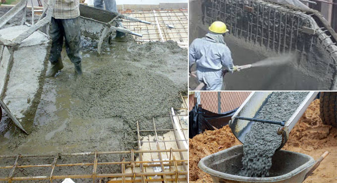
This civil engineering article sheds light on the required steps for post-concrete inspection as soon as decluttering of any concrete structure is completed.

The activities prior to arrange concrete comprise of utilization and maintenance of curing compound or other techniques of curing, form removal, concrete repair and preservation of concrete cubes. The subcontractor will inform QA/QC that curing is retained by the submittal of curing records.

Some vital Inspection points:

Given below, the details about major key inspection items to be examined and/or checked in the context of concrete post placement activities:

• Ensure that the necessary method of curing is prepared.
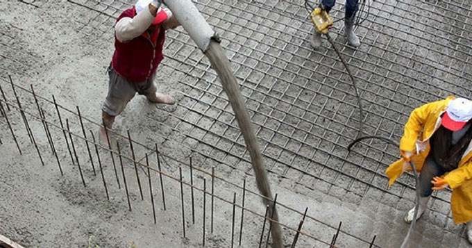
• Ensure that the placement is examined constantly to assure uninterrupted curing (watch for dry spots).

• Ensure that curing is retained for a prolonged time if necessary.
• Ensure that proper protection against bad weather is taken when necessary (hot or cold weather) as indicated in specifications.
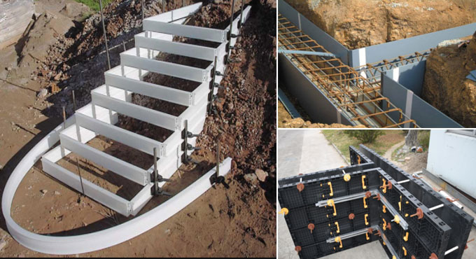
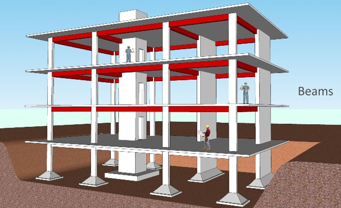
• Ensure that concrete forms are departed in exact position for prolonged time to assure that form removal will keep concrete undamaged or workers (take precautions concerning the forms supporting the weight of the concrete to make sure the concrete has attained adequate strength to sustain its own weight)

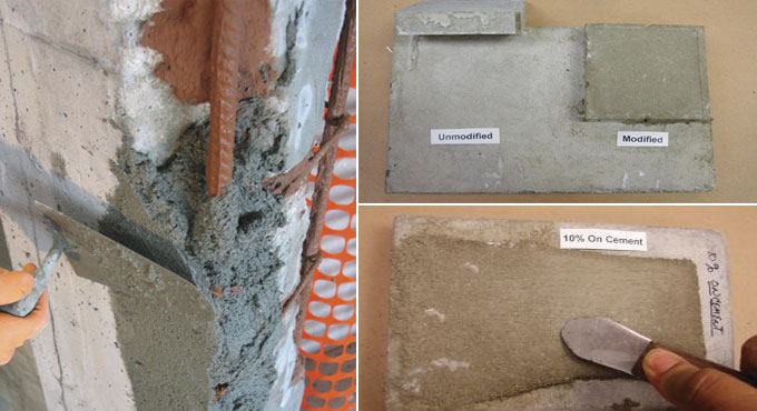
• When repair of concrete is essential, check that it is repaired compliant with specifications (on the basis of the intensity of the repair, verify if a nonconformance report is necessary)
• Ensure that concrete cylinders are preserved on site in conformity with BS codes and job site requirements
• Ensure that concrete cylinders are transported to the testing laboratory and consequently tested compliant with BS and job site requirements Documentation


The Concrete Pour Card (Attached at the end) and Concrete Test Report as well as all supporting documents associated with the concrete pour should be arranged in the master file for the specific concrete pour. These files should be retained during the construction process and prepared in compliance with the methods of Control of Quality Records. There should be a proper labeling system for the project that sustains traceability among the concrete test report and the Concrete Pour Card.

Some vital steps for concrete post-pour inspection

Read more
~~~~~~~~~~~~~~~~~~~~~~~~~
Published By
Rajib Dey
www.constructioncost.co
~~~~~~~~~~~~~~~~~~~~~~~~~

Wednesday, January 30, 2019

Details about low cost housing

Low Cost Housing is gaining popularity in recent times. This type of housing is based on productive budgeting and useful methods which facilitate decreasing the construction cost through the application of locally obtainable materials together with superior skills and technology devoid of comprising the strength, performance and longevity of the structure.

The low cost housing is performed by managing all the resources perfectly. The cost reduction is possible by suspending finishing works or utilizing them in phases.

Building Cost - The building construction cost is segregated as follow:

Building material cost : 65 to 70 %

Labour cost : 65 to 70 %

In low cost housing, building material cost is reduced due to application of the locally obtainable materials. Besides, the labour cost is also decreased by correctly making the time schedule of the work. The cost is decreased with the selection of more efficient material or by a superior design.

The cost can be decreased in the following areas :-

1) Minimize the plinth area with the use of thinner wall concept. As for instance 15 cms thick solid concrete block wall.
2) The locally obtainable material should be employed in a untraditional form like soil cement blocks instead of burnt brick.
3) Apply energy efficient materials so that less energy is consumed, as for instance, concrete block instead of burnt brick.
4) Apply eco-friendly materials in place of traditional building constituents, as for instance R.C.C. Door and window frames instead of wooden frames.
5) Plan in advance each constituent of a house and streamline the design method for minimizing the size of the constituent in the building.

6) By planning every constituent of a house the wastage of materials caused by demolition of the unplanned component of the house is bypassed.
7) Each constituent of the house should be verified whether if it’s necessary, if it is unnecessary, then that constituent should not be applied.


Details about low cost housing

Read more
~~~~~~~~~~~~~~~~~~~~~~~~~
Published By
Rajib Dey
www.constructioncost.co
~~~~~~~~~~~~~~~~~~~~~~~~~

Tuesday, January 29, 2019

The details about bills of quantities

With the measurement of quantities, the total price can be evaluated more elaborately & precisely to give cost feedback on the job, that at the same time can be applied numerically in cost planning of other works.

Bills of quantities offer the best possible ways to manage the cost of variations in the contract. It is extensively utilized for various post-tender work like material scheduling; construction planning; cost analysis; and cost planning.

The method of working out the quantities prior to tender is a crucial test regarding what is drawn and stated can in fact be built. By examining the drawings and reviewing the construction in detail is definitely helpful in recognizing the issues which may be omitted initially.

The direct costs & indirect costs should be taken into consideration for determining the entire cost of the project which are included in various segments of the BOQ.

As the cost is identified prior to commencement of the construction, a superior level of price certainty is maintained for the construction project.

Facilitates to provide a low tender price.
Accommodates with design changes and assists the cost management process.
Provides superior quality of tender document.


Minimize the risk of contractors managing the information in the BQ for their own purposes.
Bypass the risks with regard to both time and cost since the projects are calculated on the basis of the overall floor area.
The valuation of progress payment becomes simple with detail information as given in BQ.


May pass up the tendency of contractor to build up a conspire group and bid high for projects.

Video Source: Civil Engineer

~~~~~~~~~~~~~~~~~~~~~~~~~
Published By
Rajib Dey
www.constructioncost.co
~~~~~~~~~~~~~~~~~~~~~~~~~

Monday, January 28, 2019

Types of formworks found in construction

Generally, steel or concrete is used in formwork to build part of the permanent structure. Temporary formwork can be struck and recycled from any inexpensive and easily worked material, timber, steel and GRC/GRP.

The formwork that should be utilized under the water, should abide by the following conditions :

a. Support the concrete in its designed profile during the plastic phase
b. Properly affixed into position.
c. Cover the concrete from scour, washout and abrasion till unless it gets solidified.
d. Endure mistakes in development level or alignment of adjoining work
e. Ability to resist the static and dynamic loading caused by concrete, tides, waves and currents.


It is designed in the context of the permanent works and be abandoned in situ or as temporary works either to be abandoned in situ or smitten and recycled.

The following types of formworks are mostly found :-

Ceiling Formwork: Ceiling formwork belongs to the type of formwork commonly found in structures/buildings.

The formwork sheeting comprises of sheeting boards or prefabricated sheeting panels. The formwork sheeting is located on squared timber formwork bearers to be provided on main bearers capturing the forces to round timber columns. With smaller rooms, the main bearer along with two columns develops a trestle. Diagonal board bracings are arranged to manage horizontally acting forces. The round timber columns are arranged on double wedges which function as stripping aid and correction device.

Beam Formwork: Beam formwork contains prefabricated formwork sheeting parts (sheeting bottom and side sheeting panels). Such individual parts are erected on the basis of the beam dimensions stated in the project. For prefabrication of the formwork sheeting parts, a special preparation table should be created on site.

Column Formwork: Same as beam formworks, the sheeting of column formworks is prefabricated based on the column dimensions from sheeting boards attached with cover straps.

The sheeting panels are arranged in a foot rim which is secured in the soil with steel bolts.

The foot rim consists of double-nailed boards. The foot rim must be exactly measured-in because it is decisive for the exact location of the column. It has the same functions as the thrust-board for foundation or beam formwork.

When the sheeting panels are implanted in the foot rim, vertical arch timbers are arranged to undertake the forces from the cover straps of the formwork sheeting.

Around the arch timbers, that contains the function of walers, column clamps of flat steel are braced with wedges or a rim of boards is provided same as the foot rim. Supplementary formwork tying with tie wires or steel screws is not required.

The distances of the clamps are mentioned in the formwork project. Generally, they are roughly 700 mm.

The column in the formwork is laterally fastened by diagonal board braces.

Types of formworks found in construction

Read more
~~~~~~~~~~~~~~~~~~~~~~~~~
Published By
Rajib Dey
www.constructioncost.co
~~~~~~~~~~~~~~~~~~~~~~~~~

Friday, January 25, 2019

Benefits of piers constructed monolithically in bridge

When integral bridge, piers are constructed monolithically with the bridge deck, the following benefits are obtained :-

Bearing replacement cost is directly associated with the maintenance of bridges and it creates problem for the contractors. With integral bridge systems, it can be bypassed. In design standpoint, bearing replacement involves extra stresses and requirement of diaphragms in transverse design.

Movement of the bridge deck is obtained with the bending deformation of long and slender piers. Thus, it reduces the construction cost of bearings with the use of monolithic construction among bridge deck and piers.

Besides, it is less important to give extra effort to create design for drainage details and get bearing replacement. Alternatively, in maintenance perspective considerable cost and time savings can be gained with integrated bridge construction rather than applying bearings as bridge articulation.

Monolithic construction comprises of the shortest useful Euler buckling length for piers since they provide fixed supports at the interface among bridge deck and piers.

Other Factors: In two span integral bridges, temperature, creep and shrinkage, and other loads that provide longitudinal forces like seismic forces which create crucial design challenges.

These forces produce supplementary moments on the central pier increasing the demand. It requires innovative solutions in the design, ranging from implementation of arch systems to facilitate the bridge to breath up and down because of thermal actions. Unsettled soil conditions and seismic zones create the design challenges. Integrated Bridge design is an expert area in the design of bridges.

Note: In monolithic construction the piers are attached with the bridge decks irrespective of any joints and bearings.

Benefits of piers constructed monolithically in bridge

Read more

~~~~~~~~~~~~~~~~~~~~~~~~~
Published By
Rajib Dey
www.constructioncost.co
~~~~~~~~~~~~~~~~~~~~~~~~~

Thursday, January 24, 2019

Details about High Performance Concrete (HPC)

Now-a-days, High Performance Concrete (HPC) is gaining popularity. HPC denotes superior concrete performance throughout wet stage (mixing & placing process); with greater strength in hardened stage together with a greater strength in long-run as compared to normal concrete.

The HPC is comprised of different chemical cum mineral admixtures and fibres. In HPC, the proportions are designed, or engineered, to create the strength and durability required for the structural and environmental requirements of the project.

High-strength concrete contains a specified compressive strength of 8000 psi (55 MPa) or higher. Special mixing, placing, and curing practices are required to develop and manipulate high-performance concrete. Normally, comprehensive performance tests are essential to show compliance with specific project requirements.

High-performance concrete is mainly utilized in tunnels, bridges, and tall buildings due to its strength, stability, and high modulus of elasticity. It is also been applied in shotcrete repair, poles, parking garages, and agricultural applications.

High-performance concrete characteristics are developed for particular applications and environments; some of the properties that may be required include:

• High strength
• High early strength
• High modulus of elasticity
• High abrasion resistance
• High strength and permanence in rigorous environments

• Low permeability and diffusion
• Defiance against chemical attack
• High resistance against frost and deicer scaling damage
• Toughness and impact resistance
• Volume stability
• Ease of placement
• Compaction devoid of segregation
• Inhibition of bacterial and mold growth


High-performance concretes are developed with cautiously chosen high-quality materials and optimized mixture designs; these are batched, mixed, placed, compacted and cured with reference to the superior industry standards.

Normally, such concretes will contain a low water-cementing materials ratio of 0.20 to 0.45. Plasticizers are normally utilized to produce these concretes fluid and workable. High-performance concrete almost always contains a greater strength as compared to normal concrete.

High-early-strength concrete, also known as fast-track concrete, attains its specified strength at an initial age as compared to normal concrete. The time period in which a specified strength should be attained may vary from a few hours (or even minutes) to several days. High-early-strength is achieved by employing conventional concrete ingredients and concreting practices, although sometimes special materials or techniques are necessary.

Details about High Performance Concrete

Read more
~~~~~~~~~~~~~~~~~~~~~~~~~
Published By
Rajib Dey
www.constructioncost.co
~~~~~~~~~~~~~~~~~~~~~~~~~

Tuesday, January 22, 2019

Difference Between Flexible Pavement and Rigid Pavement

The pavement designing is complicated task in Transportation Engineering. The most recognized methods for pavement design are Rigid pavement and Flexible pavement. The pavement surface has good longevity and it can resist the load operating from the wheel tyres.

Given below, the functional requirement of highway pavements :-

1. Flexible pavement and Rigid pavement contain superior riding quality
2. It should be less slippery
3. It should be rigid
4. It should contain adequate friction keeping the power of the vehicle unchanged.


Variation among Rigid Pavement and Flexible Pavement

1. Flexible Pavement

a. Load is transmitted from grain to grain to the lower layers
b. The design is totally based on the subgrade strength.
c. IRC 37-2012 code is applied for making the design of flexible pavement
d. The strength of flexible pavement is influenced by the aggregate interlock, particle friction and cohesion.
e. Flexible pavement demonstrates the deflection of subgrade at the surface of the pavement.
f. Design life lasts for 15 years.


Rigid Pavement:

1. Rigid pavement contains a strong flexural strength that is considered as the vital factor of design.
2. Rigid pavement contains a concrete layer at the top, the base course and soil subgrade remain underneath.
3. Rigid pavement disperses the load over a broad area due to its high flexural strength.
4. Load is transmitted through slab action.
5. The total thickness of the pavement remains under flexible pavement.

6. IRC: 58-2011 is utilized for making the designing of Rigid pavement.
7. Design life extends for 30 years


Difference Between Flexible Pavement and Rigid Pavement

Read more
~~~~~~~~~~~~~~~~~~~~~~~~~
Published By
Rajib Dey
www.constructioncost.co
~~~~~~~~~~~~~~~~~~~~~~~~~

Monday, January 21, 2019

Variations among Load Bearing Wall and Partition Wall

The wall is categorized as follow: Load Bearing Wall, Partition Wall.

Load Bearing Walls: If beams and columns are not utilized (Frame Structure), load from roof and floors are transmitted to foundation through walls. Such walls are known as bearing walls.

The purpose of these walls is to securely transmit the load. The vital section of the walls is located adjacent to the openings of doors and windows and the positions where concrete beams stand. Minimum wall thickness should be 200 mm. The slenderness ratio of wall called as ratio of effective length or effective height to thickness should not surpass 27.

Effective height of walls with respect to actual height H

a. Lateral as well as rotational restraint 0.75 H
b. Lateral as well as rotational restraint at one end and only lateral 0.85 H restraint at other.
c. Lateral restraint but no rotational restraint at both ends 1.0 H
d. Lateral and rotational restraint at one end and no restraint at other 1.5 H


Effective length of walls of length L

a. Continuous and supported by cross walls 0.8 Length.
b. Continuous at one end and supported by cross walls at 0.9 Length the other end.

c. Wall supported by cross walls at each end 1.0 Length.
d. Free at one end and continuous at other end 1.5 Length.
e. Free at one end and supported by cross wall at other end 2.0 Length.


2. Partition Walls: If the structure belongs to frame structure than partition walls are constructed to separate floor area for different Utilities and it stands on floors. The partition walls are used to bear only self weight. Generally partition walls are thin. According to the requirement, these walls range from clay brick partition, Fly ash bricks partition, glass panel partition, wood panel partition, and aluminium and glass panels partition.

Variations among load bearing wall and partition walls

LOAD BEARING WALL

a. They bear loads from roof, floor, self-weight etc.
b. They are solid and capture more floor area.
c. Since the quantity of material is more, the construction cost is higher.
d. Stones or bricks are the main material for building up the wall.


PARTITION WALL
a. They bear self-weight only.
b. These walls are thin and as a result capture less floor area
c. Since, the quantity of material is less, the construction cost is reduced.
d. Stones are not applied for building up the walls.
Variations among Load Bearing Wall or Partition Wall

~~~~~~~~~~~~~~~~~~~~~~~~~
Published By
Rajib Dey
www.constructioncost.co
~~~~~~~~~~~~~~~~~~~~~~~~~

Saturday, January 19, 2019

Advantages of microsillica in concrete

Microsilica alias silica fume or condensed silica fume stands for is a mineral admixture that is formed with very fine solid glassy spheres of silicon dioxide. Most microsilica particles remain under 1 micron (0.00004 inch) in diameter, normally 50 to 100 times finer as compared to average cement or fly ash particles. Microsilica belongs to a by-product of the industrial manufacture of ferrosilicon and metallic silicon in high-temperature electric arc furnaces.

Microsilica may be suitable in managing heat formation in mass concrete. It can also be combined with fly ash to provide superior result.

If pozzolanic materials are integrated with concrete, the existent silica in these materials makes a reaction with the calcium hydroxide produced throughout the hydration of cement and develops supplementary calcium silicate hydrate (C – S – H) that enhances the strength and the mechanical properties of concrete.

Types of Microsilica: Microsilica is categorized as follow -

1. Powdered microsilica, 2. Condensed microsilica, 3. Slurry microsilica

Impacts of Microsilica on Concrete

1. Fresh Concrete

a. It decreases the scope of segregation, so it is applied as pumping aid.
b. It almost reduces bleeding, as a result finishing work commences before time.
c. Workability and uniformity of concrete reduces.


2. Hardened Concrete: The inclusion of microsilica enhances the following characteristics of hardened concrete -

a. Improves compressive strength that leads to improve flexural and tensile strength.
b. Bond strength
c. Abrasion resistance
d. Lessens permeability; consequently, it safeguards reinforcement steel against corrosion.
e. Impact and cavitations resistance.
f. Sulphate Resistance
g. Heat Reduction
h. Chemical Resistance


Properties of Microsilica:

1. Microsilica belongs to a grey; almost white to black powder.
2. Spherical particles remain under 1mm in diameter.
3. The mass density of microsilica is dependent on the degree of densification and differs from 130 to 600 kg/m3.
4. The specific gravity of microsilica differs among 2.2 to 2.3


Benefits:

a. Minimizes thermal cracking resulting from the heat of cement hydration.
b. Enhance the strength to resist against sulphate and acidic waters.
c. Minimizes the growth of temperature in preliminary stage.
d. Silica fume is cheap; therefore, it is inexpensive.
e. It minimizes the entire slab weight and cost.
f. Inclusion of microsilica reduces efflorescence caused by the refined pore structure and increased consumption of the calcium hydroxide.


Advantages of microsillica in concrete

Read more

~~~~~~~~~~~~~~~~~~~~~~~~~
Published By
Rajib Dey
www.constructioncost.co
~~~~~~~~~~~~~~~~~~~~~~~~~

Friday, January 18, 2019

Characteristics of polymer-Modified Mortar

Mortar is considered as one of the vital components in masonry construction. It is normally formed by mixing water with portland cement, hydrated lime and sand. If the proportions of each of these ingredients are changed, strength and other characteristics may differ. Mortar with polymeric admixtures is applied extensively and inexpensively in definite situations.

Basics and function: Polymer-modified mortar is developed by interchanging a part of the conventional binders with polymers. Polymers are included with mortar to enhance the characteristics which may contribute to adhesion, toughness, flexural or tensile strength, and resistance to chemicals.

The purpose of the polymers is to make the capacity of work and adhesion of non hardened mortar better and often need fewer quantity of extra water as compared to conventional mortar. It leads to less pores and high capacity cements, consequently the immersion of water & and penetrability to salts are decreased.

Types of Polymers: Polymer-modified mortar is commercially obtainable with all constituents already provided in the mixture. Conversely, polymer additives separated into classes, are included with mortar mix. Redispersible polymer powders like ethylene vinyl acetate are normally included with dry mortar mix.

Water-soluble polymers like polyvinyl alcohol belong to powders but are added to wet mortar mix. Aqueous latex suspensions comprise of latex particles hanged up in water to coat hydrating cement particles. At the end, liquid polymers as epoxy resins or unsaturated polyesters are included throughout mixing to develop a network of cemented polymer hydrate and thus the strength of the mixture is raised significantly.

Application: Polymer-modified mortar is employed in a wide array of mortar and concrete repair and primary construction applications. Low water level and salt infiltrations transform polymer-modified mortar suitable for masonry prone to weathering and other exterior conditions. The main objective of polymer-modified thinset mortar is to bind tile to concrete and cement board substrates devoid of immersing the tiles earlier. Polymer-modified mortars are frequently applied for repairing purposes due to their low shrinkage and capacity to tie with even solid surfaces.

Supplementary Possible Admixtures: Besides, polymers, other types of materials can be included with mortars to attain required characteristics. Color pigments may be included with mortar to change the look of the mortar. If accelerators and retarders are included, these can decrease or raise the length of time necessary for the mortar to be cured, a vital characteristic to control in severely cold or warm, humid weather. Other mortar additives range from mineral additions, like silica fume, aggregates and inert fillers, plasticizing chemical admixtures and fibers to manage shrinkage efficiently.

Characteristics of polymer-Modified Mortar

Read more
~~~~~~~~~~~~~~~~~~~~~~~~~
Published By
Rajib Dey
www.constructioncost.co
~~~~~~~~~~~~~~~~~~~~~~~~~

Thursday, January 17, 2019

Design of Beam

1. Estimation of constants. -For the specified set of stresses, determine KC, JC and RC.
2. Kc= M~cbc/M~cbc+~st
3. Jc= 1-(Kc/3)
4. Rc= 0.5*L*Kc Jc
5. Estimation of bending moment. Suppose appropriate values of overall depth and breadth of beam, and find out the effective span. Work out the self-weight and total U.D.L. and maximum bending moment in the beam.
6. Design of the section. Workout the effective depth of the beam with the following expression:
7. d= [(M)/ (RC*b)] 0.5
8. Reinforcement. Workout the area with the formula.
9. Shear Reinforcement. Workout the maximum shear force in the beam.
10. Verify for Development length at the end.
11. Ld<= (M1/V) +L0.
Design of column:
1. Find out the allowable stresses in concrete, longitudinal bars and ties.
2. Determine the super impose load that should be borne by the column.
3. Find out the area from the following expression - P= ~cc *Ac+~sc*Asc.
4. After getting details about the area, find out the dimensions of column. If it is a square of side b, then b=Ag.
5. For the specified end conditions, find out the effective length of column. Measure lef/b ratio to determine whether the column is short or long.
6. If lef/b ratio<12 it will be designed as short column or else as long column; define the area of steel Asc.
7. Determine the diameters of bars utilized as ties and find out its pitch according to the rules.
DESIGN OF FOOTING: The width B of the footing will obviously be equivalent to [W+W‟]/qo. The thickness is measured based on the bending moment as well as punching shear.
1. Depth for bending moment.
d= [M/B*Rc] 0.5
2. Depth for shear.
3. tv=V/B*d
4. Steel Reinforcement. Ast=M/tjcd
Design of Beam

~~~~~~~~~~~~~~~~~~~~~~~~~
Published By
Rajib Dey
www.constructioncost.co
~~~~~~~~~~~~~~~~~~~~~~~~~

Monday, January 14, 2019

Building materials is the newest app for civil engineer

Building Materials is an exclusive construction app for the site civil engineer, supervisors available in google play store.

It provides a complete on digital construction and building material for civil engineers. The app comprises of all the crucial notes concerning the material & construction engineering as well as building knowledge.

The app is supported with material for building construction, building materials estimation, building material and construction book.

It is one of the best civil engineering applications that can be used for acquiring knowledge on quick revision & obtaining a complete detail of construction material as well as making estimation of the materials.

Major features of building material notes:

• It is possible to make quick notes with regard to building material items.
• Digitalize your material usage with quick notes.
• Make easy notes with our application.


Generate a material construction checklist with the app.

By using this app, one can take notes of different types of construction materials like bricks, blocks, plaster, cement, sand, gravel, water-base, oil-base, concrete tile. With this app, it is possible to measure steel, brick, concrete, area etc.

To download this app from google play store, click on the following link. play.google.com

Building materials is the newest app for civil engineer

~~~~~~~~~~~~~~~~~~~~~~~~~
Published By
Rajib Dey
www.constructioncost.co
~~~~~~~~~~~~~~~~~~~~~~~~~

Friday, January 11, 2019

Some vital points to make saw cuts in concrete

The purpose of saw cuts is to make control joints in concrete to facilitate managing cracks which may occur because of shrinkage. The cuts should be created at a predetermined spacing and only as soon as the concrete has attained adequate strength but prior to internal cracking starts. So, the timing of saw cuts should be maintained properly. The exact time for creating cuts is based on several factors along with the type of admixtures and aggregate used in the concrete, the air temperature, and the concrete's mix design.

When to Saw-Cut Concrete: Besides, the concrete mix and the weather conditions, it depends on rigidity of the concrete and the type of cutting equipment applied to make the saw cuts. If the cutting is done ahead of time, an effect produced by the saw blade dragging the aggregate out of position, departing a rough, weakened edge along the cut. It also produces undo wear on diamond concrete saw blades. Sawing slowly can lead to uncontrolled cracking since the concrete contracts throughout curing.

In hot weather conditions, saw cutting commences after four hours once the concrete is poured. In cooler weather, sawing should not commence for 12 hours after pouring. The most effective method to find out whether the slab is prepared is to create trial cuts to examine raveling. Saw cutting should be commenced when the raveling stops throughout these trial cuts.

Some contractors defer sawing to defend their equipment and saw blade to minimize blade abrasion. Different types of saw blades are utilized on the basis of the concrete type and how quickly the cuts can be started. The following other factors can produce extreme blade wear and joint raveling:

• Pushing the blade too hard
• Saw cutting is done at high speed
• Applying a saw with a ben spindle
• Application of an improper saw blade


Where to Saw-Cut Concrete: Prior to commence saw cutting concrete, it is crucial to choose where these cuts will be created. It is will be useful to start saw cuts on or at the center of column lines. Joints shall be placed at 24 to 36 times the slab thickness but it should be approved by a structural engineer. Joint spacing generally varies among 10 to 18 feet based on the amount of reinforcement in the slab.

How to Saw-Cut Concrete: Various factors like curing methods, slab thickness, slab length, and base type should be analyzed prior to determine where joints should be cut. As soon as the joints are placed to be cut, mark them with a chalk line.

If water cutting equipment is applied, ensure that the water is running all the way down to the blade. The blade should be allowed to attain the desired depth, then start walking or moving the equipment following the chalk like mark. Here are some recommendations when sawing concrete:

• Never twist the saw blade.
• Do not allow the blade spin in the cut, since it will raise wear on the bond.
• While cutting concrete with heavy rebar, apply blades with soft metal segment bonds.
• It is recommended to utilize use the required PPE (personal protection equipment).


Depth of creating Saw Cuts: A proper rule of thumb is to cut the joints one-quarter to one-third the slab thickness. For a 6-inch-thick slab, it signifies cutting 1.5 to 2 inches deep. Make sure that the saw cut depth is according to the structural engineering specifications. If the joint is adequately deep, aggregate interlocking will not be sufficient to transmit the loads. If the saw cut is too shallow, random cracking may happen.

Some vital points to make saw cuts in concrete

Read more
~~~~~~~~~~~~~~~~~~~~~~~~~
Published By
Rajib Dey
www.constructioncost.co
~~~~~~~~~~~~~~~~~~~~~~~~~

Thursday, January 10, 2019

Some important points for civil site engineer

Civil engineer accomplishes several tasks at construction site. Given below, some points, tips and tricks essential for a civil engineer for doing rapid calculations and providing instant solutions to construction site problems.

Given below, some general points which civil site engineers should focus on to simplify the construction work whereas retaining the quality of construction.

Lapping should not be provided for the bars with diameters in excess of 36 mm.

Highest spacing for chair should be 1.00 m (or) 1 No per 1m2.
For dowels rod, lowest 12 mm diameter should be applied.


For Chairs, bars with minimum diameter of 12 mm should be utilized.
Longitudinal reinforcement should remain not below 0.8% and in excess of 6% of gross C/S.
Least bars for square column is 4 No’s and 6 No’s for circular column.
Main bars in the slabs should not be under 8 mm (HYSD) or 10 mm (Plain bars) and the distributors should not be under 8 mm and not in excess of 1/8 of slab thickness.


Least thickness of slab should be 125 mm.
Dimension tolerance for cubes should be + 2 mm.
Free fall of concrete is permissible maximum to 1.50m.
Lap slices should not be applied for bar greater than 36 mm.
Water absorption of bricks should not be in excess of 15 %.
PH value of the water should not be under 6.


Compressive strength of Bricks should be 3.5 N / mm2.
The binding wire in steel reinforcement should be required 8 kg per MT.
According to IS code for soil filling, 3 samples should be chosen for core cutting test for each 100m2.


Some important points for civil site engineer

Read more
~~~~~~~~~~~~~~~~~~~~~~~~~
Published By
Rajib Dey
www.constructioncost.co
~~~~~~~~~~~~~~~~~~~~~~~~~

Wednesday, January 9, 2019

Benefits of joining & pointing in brick masonry

When bricks are not fully uniform in colour and irregular in shape, the joint finishes should be designed to provide correctness and repose to premier facades with formation of the illusion of perfectness.

JOINTING: The finished profile of the original mortar joint is produced instantly since the bricks are placed later in an individual practice called as pointing. Jointing is associated with bricklaying for finishing the joint faces of the bedding mortar as work continues.

Benefits:

• Combined joint
• Consistency of joint in strength and colour, on condition that mortar is properly measured
• Lower labour costs


Drawbacks:

• Less quality control of joint finish (not all bricklayers joint well)
• Complication in retaining consistent colour all through the wall face.


POINTING: Pointing stands for the method of repairing mortar joints among bricks or other masonry elements to resist penetration of rain water or dampness.

Benefits:

• Greater joint finish
• Consistency of colour and strength
• Better choice of joint finishes
• Clean face work


Drawbacks:

• Higher labor and material costs
• Extra construction time
• When improperly performed the compound joint can’t be joined
• Requirement for expert and experienced pointers.


Structural benefits: The bricks consume moisture from the mortar when perfectly dampened prior to laying or pointing. Together with evaporation, it leads to partial de-hydration of the joint towards the joint face. So the purpose of the jointing tool is to solidify the surface of the joints fixing shrinkage cracks and defending from the ingress of driving rain.

Benefits of joining & pointing in brick masonry

Read more
~~~~~~~~~~~~~~~~~~~~~~~~~
Published By
Rajib Dey
www.constructioncost.co
~~~~~~~~~~~~~~~~~~~~~~~~~