adsense analytic

Showing posts with label Measurement. Show all posts

Wednesday, March 18, 2020

How to Calculate the Safe Bearing Capacity of Soil

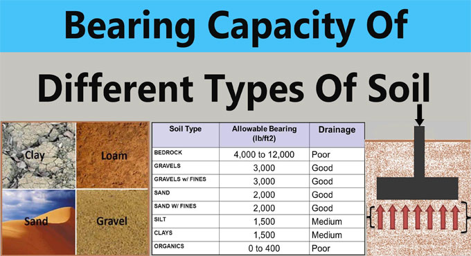
It is extremely important to figure out the safe bearing capacity of the soil at the construction site. If this is not done properly, the structure may settle, and the building may get damaged, or even collapse. For this reason, we perform various tests to find out the safe bearing capacity of the soil. Today, let us see how we can do this.

The safe bearing capacity of soil is defined as the maximum load per unit area that the soil can bear without any displacement or settlement. This is measured in terms of kilograms per square centimeter. If the load exceeds this mark, the soil will start to displace or break. This will lead to structure settlement, which can end up in destructive results.

Formula:
Safe bearing capacity of soil = (ultimate bearing capacity)/(Cross-section area x Factor of safety)


Explanation: The ultimate bearing capacity of the soil is the point at which the soil starts to displace under load.

Any soil can take up to a certain amount of load only, after which it starts to settle or displace.

The cross-section area is the area of soil on site on which the tests are being performed. It can be a square meter in general practice.

The factor of safety indicates how safe the soil capacity results must be before considering a certain type of construction. Naturally, it depends upon the type of building being constructed. It is kept at 2 for general civil constructions and 3 for high-rise or heavy constructions.

How to Calculate the Safe Bearing Capacity of Soil
~~~~~~~~~~~~~~~~~~~~~~~~~~
Published By
Rajib Dey
www.constructioncost.co
~~~~~~~~~~~~~~~~~~~~~~~~~~

Tuesday, December 31, 2019

Seismic Zones in India

In the field of seismology, seismic zones are, areas divided based on the frequency and intensity of expected earthquake. Indian subcontinent comprises of four seismic zones those are- II, III, IV and V. These zones are categorized based on scientific research related to seismicity and earthquake occurrence in the past years.

Earlier India was divided into five zones, but then, The Bureau of Indian Standards [IS 1893 (Part I):2002] decided to group the country into four seismic zones, where, the first and second zone being unified.

The Bureau of Indian Standards is responsible for publishing seismic activities in terms of seismic hazard maps and codes. They brought out a total of three versions of seismic zones; a six zone map in 1962, a seven zone map in 1966 and a five zone map in 1970/1984.

Seismic Active Zone:

Seismic Zone II: This is the area that suffers least damage of the other three zones. Intensity of earthquake lies between intensities V to VI of MM scale (MM – Modified Mercalli Intensity scale).

Zone II covers those areas which are not covered by the other zones listed below.

Seismic Zone III: Zone III receives moderate damage. This damage corresponds to intensity VII of MM scale.

States that lie under this zone are- Tamil Nadu, Orissa, Andhra Pradesh, Maharashtra, Chhattisgarh, Bihar, Jharkhand, Bihar, Madhya Pradesh, Kerala, Gujarat, Goa, Lakshadweep islands, West Bengal, Karnataka, parts of Punjab and some remaining parts of Uttar Pradesh.

Read more
Seismic Zones in India
~~~~~~~~~~~~~~~~~~~~~~~~~~
Published By
Rajib Dey
www.constructioncost.co
~~~~~~~~~~~~~~~~~~~~~~~~~~

Tuesday, December 24, 2019

Top Ten Construction Projects in World

The Construction industry is something that never stops. To achieve more living space, better infrastructure, production facility, and development, we need to be building some stuff all the time, expanding our concrete footprint everywhere. These construction projects can range from small residential houses to giant skyscrapers or miles-long bridges.

Today, we will discuss ten of these construction projects in the world, which we consider as the largest of them all. These projects not only take up huge ground area, but they are also gigantic in scope, manpower and resource usage, economic and geographical impact, and they take quite some time to build. Some of these require very different kinds of technologies to construct, as you will see below. Our list of the top ten largest construction projects includes infrastructures, industrial, and entertainment complexes.

Al Maktoum International Airport, Dubai


Spreading over 21 square miles, the Al Maktoum International Airport is the largest airport under construction ever. While the construction has been scheduled to finish in 2018, it has been delayed indefinitely. The monstrous project will eat up $32 billion in the second phase only. When finished, the airport will be able to accommodate the movements and servicing of two hundred wide-body airplanes and other assorted aircraft at one time.

Jubail II, Saudi Arabia


One of the longest-running industrial projects in the world is Jubail II, running for over 22 years. It is an industrial city, comprising of over a hundred industrial plants, a desalination plant sized eight hundred thousand cubic meters, and an oil refinery capable of producing 350,000 barrels of oil every day. The grounds of this project will be crisscrossed with miles and miles of highways, railroads, and streets to connect it with the rest of the country. It has started the second phase of expansion worth $11 billion back in 2014 is scheduled to continue building till 2024.

GMR Project, Libya

~~~~~~~~~~~~~~~~~~~~~~~~~~
Published By
Rajib Dey
www.constructioncost.co
~~~~~~~~~~~~~~~~~~~~~~~~~~

Monday, August 19, 2019

Some useful tips to measure loads on column, beam and slab

In order to work out the total load on columns, Beam and Slab, there should be clear ideas on the types of loads enforcing on the column.
Different Loads operating on Column:
1) Column Self Weight X Number of floors
2) Beams Self Weight per running meter
3) Load of walls per running meter
4) Total load on Slab (Dead load + Live load + Self weight)
Apart from above loading, the columns are also susceptible to bending moments which should be taken into consideration in the final design.
For Colomn: The Self weight of Concrete remains approx 2400 kg/m3, that is similar to 240 kN and self weight of steel is approx 8000 kg/m3.
Therefore, if we consider a column size of 230 mm x 600 mm with 1% steel and 3 meters standard height, the self weight of column is approx 1000 kg per floor that is equivalent to 10 kN.
At the time of making calculation, self weight of columns is taken as 10 to 15 kN per floor.
For Beam: Similar method is also used for making calculations of beam. Suppose, each meter of beam contains dimensions of 230 mm x 450 mm without slab thickness. Therefore, the self weight should be approx 2.5 kN per running meter.
For Walls: The Density of bricks differs among 1500 to 2000 kg per cubic meter. For a brick wall with thickness 6 inch, height 3 meter a length 1 meter. The load / running meter should be equivalent to 0.150 x 1 x 3 x 2000 = 900 kg, that is identical to 9 kN/meter. This method is useful for working out the load of brick per running meter for any brick type.
For aerated concrete blocks and autoclaved concrete blocks similar to Aerocon or Siporex, the weight per cubic meter should remain 550 to 700 kg per cubic meter.
When these blocks are utilized for construction, the wall loads for each running meter should remain as low as 4 kN/meter, the cost of the project is decreased considerably with the use of this block.
For Slab: Suppose, the slab contains thickness of 125 mm.
Therefore, self weight of each square meter of slab should be = 0.125 x 1 x 2400 = 300 kg that is identical to 3 kN.
Now, If finishing load is taken to be 1 kN per meter and superimposed live load to be 2 kN per meter. Therefore, from above data, the load of slab can be calculated as 6 to 7 kN approximately per square meter.
Factor of Safety: At the end, once the total load on a column is computed, consider the factor of safety that is very crucial for any building design for safe and convenient performance of building during its design life cycle.

Some useful tips to measure loads on column, beam and slab

~~~~~~~~~~~~~~~~~~~~~~~~
Published By
Rajib Dey
www.bimoutsourcing.com
~~~~~~~~~~~~~~~~~~~~~~~~

Friday, June 28, 2019

Details about Ultrasonic Pulse Velocity

This test is conducted for the purpose of evaluating the concrete quality with ultrasonic pulse velocity method with adherence to IS: 13311 (Part 1) – 1992. The underlying principle of this test is –
Under this method, testing is done by sending an ultrasonic pulse through the concrete and time of movement is calculated. Relatively, greater velocity exists if the quality of concrete is good with respect to density, consistency, homogeneity etc.
The following method is applied to ascertain the strength of hardened concrete with Ultrasonic Pulse Velocity :-
i) Making it ready for use: Prior to changing to the ‘V’ meter, the transducers should be attached to the sockets leveled as “TRAN” and ” REC”.
The ‘V’ meter is activated with either: a) the internal battery, b) an external battery or c) the A.C line.
ii) Set reference: A reference bar is arranged to examine the instrument zero. The pulse time for the bar is inscribed on it. Prior to set it on the opposite ends of the bar, provide a coat of grease to the transducer faces. Fine-tune the ‘SET REF’ control unless the transit time of reference bar is captured on the instrument read-out.
iii) Range selection: For greater precision, it is suggested that the 0.1 microsecond range should be chosen for path length upto 400mm.
iv) Pulse velocity: After detecting the exact test points on the material to be tested, thorough measurement of the path length ‘L’ should be done. Provide couplant to the surfaces of the transducers and press it firmly onto the surface of the material.
It is suggested not to shift the transducers at the time of taking a reading since noise signals and errors in measurements may occur. Keep on retaining the transducers onto the surface of the material unless a reliable reading is shown on the display that is the time in microsecond for the ultrasonic pulse to pass through the distance ‘L’. The mean value of the display readings should be captured while the units digit follows among two values.
Pulse velocity=(Path length/Travel time)
v) Partition of transducer leads: It is recommended to avoid the two transducer leads from getting in touch with each other at the time of taking the transit time measurements.
If it is not performed, the receiver lead will pick-up unnecessary signals from the transmitter lead and it leads to an wrong display of the transit time.
Interpretation of Results
The quality of concrete with regard to consistency, occurrence or nonexistence of internal faults, cracks and segregation, etc, indication of the level of workmanship provided, can thus be examined with the following guidelines which are changed for defining the quality of concrete in structures with regard to the ultrasonic pulse velocity.
Details about Ultrasonic Pulse Velocity

~~~~~~~~~~~~~~~~~~~~~~~~
Published By
Rajib Dey
www.constructioncost.co
~~~~~~~~~~~~~~~~~~~~~~~~

Saturday, June 8, 2019

Some vital tips to develop a column independently

A column footing generally stands for a block of concrete that is poured in the bottom of a hole with the purpose of allocating the weight provided on the column to a greater area. As a result, the columns can’t go down into the ground in due course. Given below, some useful guidelines to pour the footings independently.
Step 1 - Measure the Footing: Label the spot to locate the correct center point of the column.
After that, work out and mark out a square that is 12 inches larger regarding the size of the column, and excavate the hole. Standard depth should be 12 inches along with one extra inch for each three inches of column. As for instance, the minimum depth should be 14 inches for a six-inch column. More is always recommended.
Step 2 - Level the Bottom: The bottom of the hole should be leveled. If it is not possible to work with a shovel because of shortage of space, utilize a concrete trowel.
Then, take the measurement from the bottom 12 inches along with the depth added for column size, and fix a nail into the side of the hole at that depth on all four sides. Instead, provide a stake into the bottom of the hole, leaving that amount of the stake uncovered.
Step 3 - Measure the Concrete required: Cut a piece of wire mesh as per size of the hole, and put aside. It is assumed that minimum one full bag of concrete should be needed for the column footing or possibly more, but the formula for making perfect measurement is L x W x H / 12 to obtain the result for the number of bags required, rounded up. The height should be the distance from the bottom of the hole to the nails (or the top of your grade stake).
While arranging a column permanently, work out the concrete to fill the hole to within three inches of the top. Apply a mix containing small rocks in it since these rocks will arrange reinforcement and avoid cracking.
Step 4 - Pour the Footing: Mix the concrete based on your calculations. It is suggested not to mix excessively than required amount to fill the hole up to the nails at this time. It will be the actual footing and it should be poured discretely first, prior to adding the permanent concrete setting. Shovel or pour the concrete into the hole, but take precautions not to cave in the sides. Set the wire mesh down into the concrete, roughly halfway to the bottom.
The finishing of the surface should be smooth, but not slippery. Employ the nails as a guide for the finish depth along with them hardly over the top of the footing.
As these nails are only a guide, therefore, apply a torpedo level for leveling the footing. Allow a footing to be cured for minimum 48 hours prior to setting the column.
Step 5 - Set the Columns: While setting permanent columns, arrange one end on the footing after it is cured. Brace the column to retain it perfectly in vertical direction while checking on all sides. After that, mix the remaining concrete from your calculation and fill the hole upto three inches of the top.
Some vital tips to develop a column independently

~~~~~~~~~~~~~~~~~~~~~~~~
Published By
Rajib Dey
www.constructioncost.co
~~~~~~~~~~~~~~~~~~~~~~~~

Friday, May 17, 2019

Construction Drawing Types In Building

In construction several types of drawings are used to fulfill various purposes. These are known as construction drawings or working drawings.

As for example, working drawing is created for construction project, drawing for approval is intended for submitting to government agencies for sanction and sanctioned drawing is finally delivered to construction site.

After proper examination, justification and rectification in different phases, the drawing is accepted for construction. Construction drawing should contain detail measurement and clear section of each section of building. The following types of drawings are mostly found in construction works :-

• Architectural drawing
• Structural drawing
• Plumbing & sanitary drawing
• Electrical drawing
• Finishing drawing etc.


Architectural drawing: This type of drawing provides the entire view of building. It depicts the position of a building as well as where to arrange each parts of building etc. It retains several other drawing sheets of various names like plan, elevation, section etc.

Structural drawing: It focuses on everything about structure like strength of various segments of structure, structural material, placement, grade and size of reinforcement etc. It also comprises of several other drawing sheets within it with different titles.

Plumbing and sanitary drawing: This type of drawing demonstrates the exact positon of sanitary and water supply piping and fixture and how to attach each fixture etc.

Electrical drawing: This type of drawing provides the position and details of electrical wiring, fixtures and sub-station etc. It also presents the electrical load calculation.

Finishing drawing: It contains all drawing regarding finishes and out looking of building like tiles, marble granite etc. Sometimes this type of drawing is contained with architectural drawing.

Construction Drawing Types In Building

Read more
~~~~~~~~~~~~~~~~~~~~~~~~
Published By
Rajib Dey
www.constructioncost.co
~~~~~~~~~~~~~~~~~~~~~~~~

Wednesday, May 15, 2019

Steps involved in cement concrete works

Given below, brief specifications for executing cement concrete works for different objectives :-

1. Materials for Cement Concrete: Different types of materials cement, aggregates and water are required for cement concrete works. The aggregates are categorized as fine aggregates (sand) and coarse aggregates. The aggregates should comprise of inert material and should be clean, dense, hard, robust, long-lasting, non-absorbent. Besides, it should have the ability to make superior bond with the cement mortar.

Cement - Fresh Portland cement or pozzolana Portland cement (PPC) should be used according to requirement or specification and should contain the necessary tensile and compressive strength and fineness.

Fine Aggregates - Course sand with hard, sharp and angular grains should be utilized as fine aggregate or sand and it should get through 5mm (3/16”) square sieves or mesh. It should contain standard quality and does not contain dust, dirt and organic matters. Sea sand is not recommended for concrete works. Fine aggregates should comprise of crushed stone or manufactured sand if indicated.

Coarse Aggregates - These should comprise of hard broken stone of granite or similar stone and does not contain dust, durst and other foreign materials. The size of stone ballast should remain 20mm (0.75 inches) and less and should be arranged on 5mm (0.25 inch) square mesh. These should be well grades to retain voids under 42%.

The size of coarse aggregate is based on the thickness of concrete and nature of work. As for instance, size of coarse aggregates for building works should remain 20mm and 40mm to 60mm sizes are applied for road work and mass concrete works.

Water - The quality of water should be same as drinking water and it does not contain alkaline and acid matters.

2. Proportioning of Cement Concrete: The proportions in cement concrete should be according to the design and strength requirements. The proportion can be 1:2:4 (M15 concrete) or 1:1.5:3 for M20 concrete. The proportions of 1:2:4 concrete include the ratio of cement: sand: coarse aggregates by volume until indicated. Least compressive strength of concrete of 1:2:4 mix proportion should be 140 kg/sq.cm or 2000 lbs/sq.in on 7 days.

3. Measurement of Materials: Sand and coarse aggregates are calculated by volume with boxes. Cement should not be calculated by box, one bad of cement of 50kg weight should be treated as 1/30 cu.m or 1.2 cu.ft volume. Size of measured boxes may be 30 cm x 30 cm x 38 cm or 35 cm x 35 cm x 28 cm similar to the content of one bag of cement.

All materials should be dry and in case of utilizing damp sand, compensation should be done with extra quantity sand to the extent necessary for bulking of sand.

4. Mixing of Cement Concrete: Mixing of concrete should be done with machine to attain superior quality. For small works, hand mixing by batches is suitable.

5. Checking for Concrete Slump: Slump test should be conducted constantly to control the addition of water and to retain the desired consistency. A slump of 7.5cm to 10 cm (3 inches to 4 inches) is perfect for building work and 4 cm to 3 cm (1.5 inch to 2 inches) is ideal for road work.

6. Formwork for Concrete Works: Formwork centering and shuttering should be arranged as per need and the standard specifications prior to place concrete to confine or to support or to retain the concrete in exact location. The inside surface of the concrete should be oiled with formwork oils so that the concrete can’t stick to it.

Before placing concrete, water should be sprinkled over the base and formwork where the concrete will be arranged. Forms should not be detached prior to 14 days in general, side forms may however be detached after 3 days of concreting.

7. Placing of Concrete: It is necessary to place concrete gently in layers not surpassing 15cm or 6 inches and it should be consolidated by pinning with rods and tamping with wooden tampers or with mechanical concrete vibrating machines unless a solid concrete is produced.

Concrete should be placed constantly. If the placing of concrete is postponed for rest of the day or for the following day, the end should be sloped at an angle of 30 degrees and made rough for jointing again.

Curing of Concrete: After about two hours of placing when the concrete starts to become solid gradually, it should be retained moist by covering with wet gunny bags or wet sand for 24 hours and then curing by flooding with water making mud walls of 7.5 cm or 3 inches high or by covering with wet sand or earth and kept damp constantly for 15 days.

Steps involved in cement concrete works

Read more
~~~~~~~~~~~~~~~~~~~~~~~~
Published By
Rajib Dey
www.constructioncost.co
~~~~~~~~~~~~~~~~~~~~~~~~

Tuesday, January 29, 2019

The details about bills of quantities

With the measurement of quantities, the total price can be evaluated more elaborately & precisely to give cost feedback on the job, that at the same time can be applied numerically in cost planning of other works.

Bills of quantities offer the best possible ways to manage the cost of variations in the contract. It is extensively utilized for various post-tender work like material scheduling; construction planning; cost analysis; and cost planning.

The method of working out the quantities prior to tender is a crucial test regarding what is drawn and stated can in fact be built. By examining the drawings and reviewing the construction in detail is definitely helpful in recognizing the issues which may be omitted initially.

The direct costs & indirect costs should be taken into consideration for determining the entire cost of the project which are included in various segments of the BOQ.

As the cost is identified prior to commencement of the construction, a superior level of price certainty is maintained for the construction project.

Facilitates to provide a low tender price.
Accommodates with design changes and assists the cost management process.
Provides superior quality of tender document.


Minimize the risk of contractors managing the information in the BQ for their own purposes.
Bypass the risks with regard to both time and cost since the projects are calculated on the basis of the overall floor area.
The valuation of progress payment becomes simple with detail information as given in BQ.


May pass up the tendency of contractor to build up a conspire group and bid high for projects.

Video Source: Civil Engineer

~~~~~~~~~~~~~~~~~~~~~~~~~
Published By
Rajib Dey
www.constructioncost.co
~~~~~~~~~~~~~~~~~~~~~~~~~