Quantity Take Off or QTO is a well known project estimating company serving to the contractors, home builders, architects, design- build firms and sub contractor trade. We are providing estimating service since 2002 with a great chronicle of success.
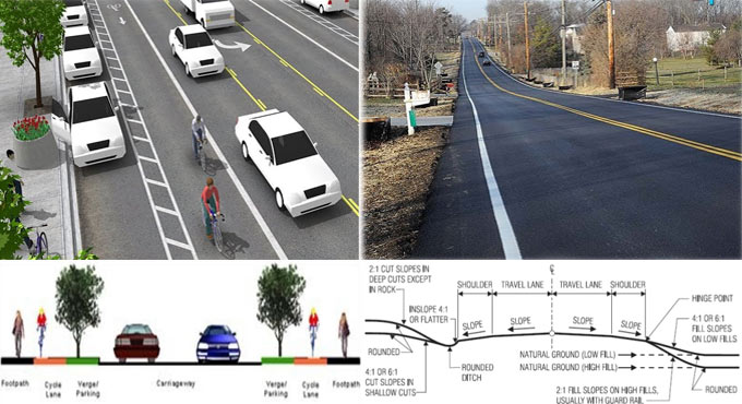
Given below, the details of cross sectional components of a road 1) Right of way: Right of way or permanent land stands for the area of land obtained and conserved for construction and formation of a road along its alignment. The width of right of way is termed as permanent land width or road land width. 2) Road way / Formation width: The top width of a highway embankment or bottom width of highway cutting exclusive of the side drain is known as roadway width or formation width. It belongs to the sum of width of carriageway and the shoulders. 3) Carriageway: Carriageway or pavement or crust is defined as the segment of roadway developed for movement of vehicular traffic 4) Shoulder: The segments of roadway among the exterior edges of the pavement and edges of the top surface of the embankment or inside edges of the side drains in cutting are termed as shoulders. The objective of shoulders i) They offer lateral strength to the carriageway. ii) They function as parking place for vehicle for emergency purpose. iii) They arrange space for constructing road signals. iv) They arrange space for animal drawn vehicles, cyclists, pedestrians. 5) Berm: The segments of land width kept among the toe of road embankment and the inner edges of borrow pits or the segments amid the top edges of road in cutting and the adjacent edges of spoil banks on either side are described as berm. 6) Building Line: It refers to the line, on either side of the road, among which and the road; no building activity can be done at all. 7) Control Line: It refers to the line which shows the nearby restraint of future unrestrained building activity concerning a road. It implies that though building activity is not entirely combined among the building line and control line, the nature of building allowable here is restricted.
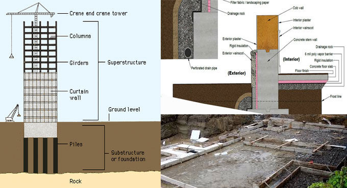
The foundations should remain as shallow as possible, in conformity with climatic effects and strength of the surface soil; specifically in waterlogged ground. For large underground structure, shoring work design details should be perfectly defined. The structure should be considerably inflexible. Foundation designshould be inexpensive & supported with updated technology to curtail piling cost. Ground treatment work should be carried on consequently. Designers should be well versed with the presumptions provided in design, the changeability of ground conditions, the occasional in-applicability of refined soil analyses and the feasibiity of construction. Soil investigation report should be prepared by an experienced Geo-technical Engineer. The assessment report should comprise of all essential data.
The construction on ground properties provides various impacts like vibration from piling, damage of ground due to excavation in unfavorable weather conditions, elimination of overburden, periodical change in the water-table, compaction of the ground by construction plant.
Impact of unstable shape, length and inflexibility of the foundation, and the requirement for movement and settlement joints.
After-effects on completed foundations concerning sulfate attack on concrete, ground movements because of frost heave, shrinkable clay, and the impacts of trees; also alterations in local environment, e.g. new construction, re-routing of heavy traffic, installation of plant in adjacent factories creating impact and vibration.
Fast but expensive construction may be more economic than low-cost but slow construction to clients needing quick return on capital investment.
Impact of new foundation loading on current adjacent structures.
~~~~~~~~~~~~~~~~~~~~~~~~ Published By Rajib Dey www.constructioncost.co ~~~~~~~~~~~~~~~~~~~~~~~~
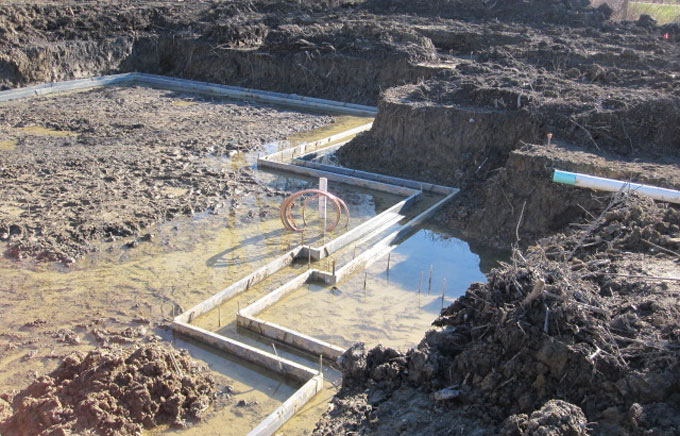
The adjoining buildings are greatly impacted with trench excavation and lead to settlement. This construction article briefly explains how to gauge the impact of trench excavation on adjoining buildings with rule of thumb.
The two factors are mainly responsible for impact of trench excavation on the buildings:
• Soil relaxation because of excavation • Diminishing of groundwater owning to excavation
When a trench is excavated adjoining a building, soil relaxation and subsequent settlement of the building is increased.
So, there should be sufficient support for the trench to resist soil relaxation. On the other hand, excavate the trench far from the foundation but it will not be a legitimate option always.
Besides, a rule of thumb is applied to examine whether the trench excavation affects the nearby building or not. Draw a line with 2H:1V from the bottom of the foundation. If the trench remains within this line, then engineer shall look forward to soil relaxation and eventual settlement of building foundation.
Lastly, if the soil at job site comprises of loose sandy soil, then draw the line with 3H:1V instead of 2H:1V.
Diminishing of Groundwater due to excavation: Generally, groundwater proceeds and seeps into the excavation from the adjacent areas of the trench. It will reduce the level of ground water in the trench vicinity area. Effective stresses are raised due to groundwater lowering and accordingly the foundation experiences settlement.
Last but not least, diminishing ground water raises effective stress in clay layer and higher effective stress leads to foundation settlement.
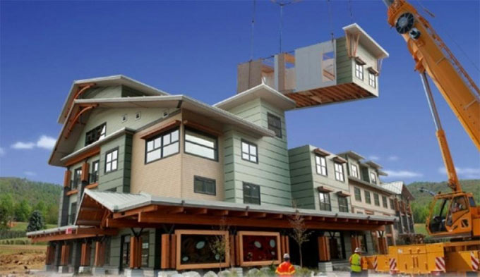
Modular construction belongs to a method by which a building is developed off-site, under controlled plant conditions, with the use of the equivalent materials and designing based on the similar codes and standards as traditionally built facilities. The construction can be done very rapidly. Buildings are built up in “modules” and assembled on site retaining the similar design intent and specifications. Due to the factory-controlled process, fewer wastes are produced with fewer site disturbances and the construction process becomes tighter. Greater Flexibility and Reuse: Modular buildingsare easily detached and the modules are displaced or refurbished for being utilized newly thus curtailing the demand for raw materials and reducing the amount of energy extended to develop a building to fulfill the new requirement. Less Material Waste: While developing in a factory, waste is reduced by recycling materials, controlling inventory and safeguarding building materials. Superior Air Quality: Since the modular structure is physically finished in a factory-controlled setting with dry materials, the possibility for high levels of moisture being confined in the new construction is removed. Compact Construction Schedule: Construction of modular buildings continues all together with site work & foundation work, facilitating the projects for being finished in half the time (30% to 50% faster) of conventional construction. Removal of Weather Delays: 60 - 90% of the construction is done inside a factory, which alleviates the risk of weather delays. Buildings are captured quicker, facilitating a speedier return on investment. Built to Code with Quality Materials: Modular buildings are constructed to satisfy or go beyond the identical building codes and standards as site-built structures, and the equivalent architect-specified materials applied in typically constructed buildings are utilized in modular construction projects – wood, concrete and steel. Modular buildings are constructed with the identical materials and to the similar building codes and architectural specifications as conventional construction. After being assembled, they are physically impossible to differentiate from their site-built counterparts. Safest Construction: The interior construction environment minimizes the risks of accidents and associated obligations for workers. Superior Engineered Building & BIM: PMC depends on improved BIM for visualization to evaluate the energy performance and recognize the most money-spinning efficiency measures. PMC is best suited where the construction method is already a collaboration of systems, materials and people. Unlimited Design Scopes: Modular units are designed to accommodate with external aesthetics of any prevailing building and modular units.
Read more
~~~~~~~~~~~~~~~~~~~~~~~~
Published By
Rajib Dey
www.constructioncost.co
~~~~~~~~~~~~~~~~~~~~~~~~
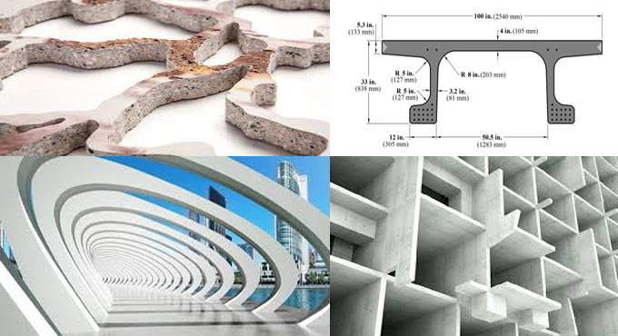
Ultra-High PerformanceConcrete(UHPC) alias reactive powder concrete (RPC), is a high-strength, ductile material that is formed by integrating portland cement, silica fume, quartz flour, fine silica sand, high-range water reducer, water, and steel or organic fibers. The compressive strengths of this type of concrete is up to 29,000 pounds per square inch (psi) and flexural strengths up to 7,000 psi. The materials are generally delivered in a three-component premix: powders (portland cement, silica fume, quartz flour, and fine silica sand) pre-blended in bulk-bags; superplasticizers; and organic fibers. The ductile behavior of this material is an elementary feature, with the strength to deform and support flexural and tensile loads, even after initial cracking. The application of this material for construction is streamlined with the removal of reinforcing steel and the capacity of the material to be virtually self placing or dry cast. The strong durability characteristics is formed because of the combination of fine powders chosen for their grain size (maximum 600 micrometer) and chemical reactivity. The outcome is a greater compactness and a small, disconnected pore structure. Higher density results in creating fewer voids inside, minimizing the scopes for water to infiltrate and create problems throughout the freeze-thaw process. The dense packing also increases the strength of UHPC significantly. To minimize the carbon footprint of the material, a byproduct of the steelmaking industry (ground slag) is utilized to substitute a significant part of the cement and simultaneously allows to improve the packing density. A major component in UHPC is steel fibers which include strain-hardening properties to the concrete and as a result when it yields the concrete will bear extreme load before it fails in due course. UHPC provides huge benefits which range from reduced global costs like formwork, labor, maintenance and speed of construction. Various usages are found bridge beams and decks, solid and perforated wall panels/facades, urban furniture, louvers, stairs, large-format floor tiles, pipes and marine structures. 1. Plumb Bob (For buildings less than 20m in height) 2. Optical Plummet (A transparent plastic sheet is used as a target for checking verticality of tall buildings) 3. Theodolite Given below the details of material characteristics for UHPC: Strength Compressive: 120 to 150 MPa (17,000 to 22,000 psi) Flexural:15 to 25 MPa (2200 to 3600 psi) Modulus of Elasticity: 45 to 50 GPa (6500 to 7300 ksi) Durability Freeze/thaw (after 300 cycles): 100% Salt-scaling (loss of residue): < 60 g/m2 (< 0.013 lb/ft3) Abrasion (relative volume loss index): 1.7 Oxygen permeability: <10-20 m2 (< 10-19 ft2) Cl - permeability (total load): < 10 C Carbonation depth: < 0.5 mm (< 0.02 in.) To get more detail information, go through the following link.precast.org
~~~~~~~~~~~~~~~~~~~~~~~~
Published By
Rajib Dey
www.constructioncost.co
~~~~~~~~~~~~~~~~~~~~~~~~
Setting survey process is applied to set out the exact position of a projected structure inside the legal boundaries of a plot of land. The objective of setting out is to set out perfect position & levels of building lines and road alignments for a projected structure as per construction plans by applying different techniques and instruments. This type of survey is very vital while going to set up any type of construction work. Generally, a set-out survey comprises of the process for transforming a building design onto the land itself in order that the builders can abide by the process throughout construction. Throughout the process, major points are set up and markers are applied for the progression of the building process and maintain perfectness. For large scale projects like high rise buildings and developments, multiple set-out surveys are required as the construction advances. This type of survey is mainly undertaken for the earthworks, roads, car parks, sewerage, water and the actual buildings themselves. Methods of Setting Out Survey
1. Setting out buildings by coordinates 2. Setting out with theodolite and level 3. Examining verticality
4. Setting out and alignment in steel framed buildings 5. Alignment and verticality in form work 6. Control and computation for route surveying
Setting Out Building by Coordinates
A building is set out by adopting referencing from an already established baseline. An asymmetrical building or a building with complicated geometry can also be established by applying the equivalent process. For each corner of the building, a grid line is set up from the baseline.
Examine Verticality - The verticality of points in a building is examined with the following surveying instruments:
1. Plumb Bob (For buildings less than 20m in height) 2. Optical Plummet (A transparent plastic sheet is used as a target for checking verticality of tall buildings) 3. Theodolite
Setting out Survey works also contains the following :-
Landfill means an engineered site where waste is separated from the atmosphere underneath the ground or on top unless it is secured and entirely dissolute biologically, chemically and naturally.
Benefits of landfilling:
a. Burying can lead to energy formation with the conversion of landfill gas as for instance methane and CO2. b. Landfill byproducts are utilized as direct/indirect fuel for combustion. c. Easy observation because of particular location. d. It can be reprocessed as well as applied as parks or farming land. e. All the reusable materials are utilized prior to closing. f. Organic material is segregated and applied for compost or formation of natural gas. g. Considerably inexpensive.
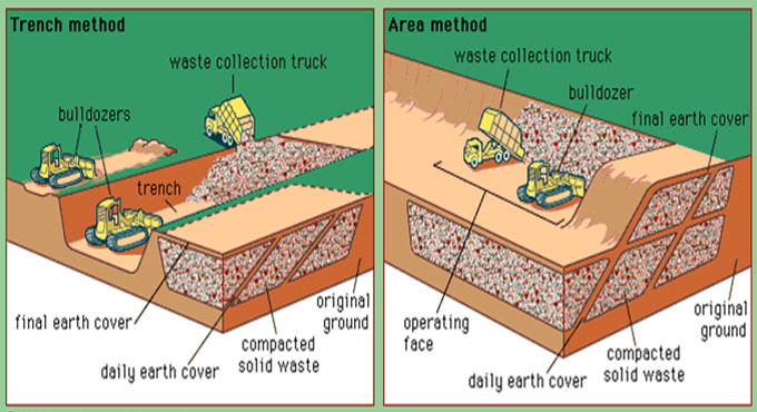
Different types of landfills methods :-
1. Area method (over ground level)
a. It is suitable for flat ground or terrain and not suitable for the excavation of trenches. b. Prior to actual land filling, an earthen levee is built up against which waste are arranged in thin layers and compressed. c. Depth of layer attains a height of 200 to 300 cm. d. Cover material with 15 to 30 cm deepness is arranged after every layer. e. A complete lift along with the cover is defined as a cell. f. This method is effective for the disposition of huge amounts of solid waste.
2. Trench Method (Underneath ground level)
a. It is suitable where cover material is present at construction site and the water table is located under the surface. b. Waste are arranged in trench and compressed in thin layers. c. After the compression of layer, height attains design height and the cover material is arranged over the compressed layer. d. Some trench is then sustained and filled correspondingly. e. It is perfect for the areas where the waste is considerably minimum.
3. Depression/Valley Method
a. It is suitable for the areas where natural or artificial depressions remain and these are utilized for land filling. b. It is based on the geometry of the site as well as geography of the site and entry to site. c. The general method is to arrange in such a way that the water should not be stored behind the landfill.
4. Slope Method
a. It is effective for hilly areas since flat ground is not available for land filling. b. Waste is arranged along the sides of current hill slope. c. Managing incoming water from hill side slopes is a crucial factor for creating the design of such landfills. d. It is generally applied for flat or little undulating regions. e. Alteration of both the area and the trench method and employs specific technique of both.
Post-tensioned concrete slabs in buildings provide various benefits over reinforced concrete slabs & other structural systems toward both single and multi-level structures. Described below, some of the advantages of the slabs :- Longer Spans: Longer spans are utilized to lessen the number of columns. It leads to bigger, column free floor areas which significantly enhance the adaptability of application for the structure as well as leads to greater rental returns. Entire structural cost: The complete cost of materials, labor and formwork which are essential to build up a floor is decreased for spans higher than 7 meters and consequently leads to huge cost savings. Minimized floor to floor height: Thinner slabs are utilized for the similar imposed loads. The decreased section depths facilitate least building height together with consequent savings in facade costs. As a substitute, toward bigger buildings, it facilitates more floors to be developed inside the original building envelope. Deflection Free Slabs: Unwanted deflections under service loads are virtually removed. Water-resistant slabs: Post-tensioned slabs are designed to remain free from cracks and as a result water-resistant slabs should be formed with proper design, detailing and construction. The selection of concrete mix and curing method together with standard workmanship are also very important. Early formwork stripping: The earlier stripping of formwork and curtailed backpropping requirements facilitate rapid construction cycles as well as fast reprocessing of formwork. Materials Handling: The decreased material quantities in concrete and reinforcement significantly offer benefit to on-site carnage requirements. The stability of post-tensioning strand is roughly 4 times that of traditional reinforcement. So, the whole weight of reinforcing material is considerably minimized. Column and footing design: The decreased floor dead loads are applied to create cost-effective design of the reinforcement concrete columns and footings. In multi-storied buildings, decreased column sizes may raise the floor net rentable area.
Under top down construction method, the basement concrete slabs function as lateral bracing toward the perimeter wall system. Ground level and first basement slabs are poured, with access holes left to facilitate excavation below. Since every succeeding sub-grade level is finished, the floors perform as lateral bracing toward the perimeter wall system. Top-down method is mostly suitable for two types of urban structures, tall buildings containing deep basements and underground structures like car parks, underpasses and subway stations. In such a circumstance the basement floors are built up as the excavation steps forward. The top/down method is utilized for deep excavation projects where tieback installation can’t be done and soil movements should be reduced. Top-down construction method saves the entire construction time. So, it is mainly implemented for some major projects where time is a key factor. The sequence construction starts with retaining wall set up and then load-bearing elements to support the future super-structure. The basement columns (generally steel beams) are built up prior to starting of excavation and rest on the load bearing elements. These load bearing elements normally belong to concrete barrettes constructed under slurry (or caissons). Construction method: Given below, the detail construction method for top down construction :-
• Built up the retaining wall. • Build up piles. Arrange the steel columns or stanchions where the piles will be developed. • Carry on the first phase of excavation. • Cast the floor slab of first basement level • Start to build up the superstructure • Carry on the second phase of excavation; cast the floor slab of the second basement level. • Reiterate the similar method unless the required depth is attained. • Develop the foundation slab and ground beams, etc. Finish the basement work. • Continue constructing the superstructure unless it is completed.
To learn the step-by-step process in detail, go through the following video presentation.
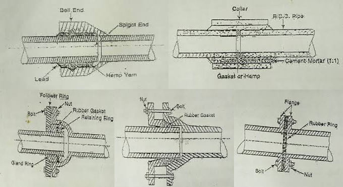
The following types of sewer joints are generally found :- 1. Bell and Spigot Joints. 2. Collar Joints. 3. Flexible Joint. 4. Expansion Joint. 5. Flanged Joint. Bell and Spigot joints: This joint is also termed as socket and spigot joint. This type of joint is mostly found in cast iron pipes containing different sizes and concrete pipes under 60 cm in diameter. The pipes which should be attached with this joint are built up in such a manner that one end is expanded and the other end is normal. The expanded end is defined as socket or bell and the normal end is spigot. The spigot end is placed into the bell end and the void of the joint is stuffed with molten lead or bitumen or cement mortar. Collar joints: In this type of joint, the ends of sewer are plain. Prior to attach, the pipes are carried face to face at the equivalent level and a collar of marginally larger diameter is arranged over the joint. Then the annular gap among the pipes and the collar is stuffed with cement mortar (1:1). The collar joints are utilized for sewers of big diameter. Flexible joint: This joint is utilized at such areas where settlement is subject to happen as soon as the pipe is arranged. With this type of joint, one pipe contains spigot end and other pipe contains socket end. The spigot is set up into the socket and the annular space developed among the socket and spigot is stuffed with bitumen. Expansion joint: This joint is adopted at places where pipes expands or contracts due to variation in atmospheric temperature. Here the socket end is cast flanged and the spigot end is plain. A flanged ring and a rubber gasket are arranged in place on the spigot end. Then the spigot end is entered into the socket end nut and bolts are secured. Flanged joint: This joint is frequently utilized for temporary work. The pipe applied in this type of joint contains flanges on both ends. At the time of joining the pipes, a rubber gasket is entered among the flanges and nut bolts are secured. To get more information, go through the following linkcivilnoteppt.com
~~~~~~~~~~~~~~~~~~~~~~~~
Published By
Rajib Dey
www.constructioncost.co
~~~~~~~~~~~~~~~~~~~~~~~~
If the water applied for concrete preparation contain impurities, the properties of concrete is influenced in the following manner: a) The strength & longevity of concrete is decreased because of the existence of the impurities in the mixing water. It is found that water with extreme amount of dissolved salts weakens the compressive strength by 10 to 30% as compared to potable water. b) The setting time of cement is modified. Existence of Zinc chlorides delays the setting of concrete to significantly so that no strength test can be done at 2 and 3 days.
Contrary, the existence of calcium chloride speeds up the setting and hardening. c) Existence of extreme chlorides leads to dampness, surface efflorescence & raise the corrosion of reinforcing steel. d) Existence of algae in water decreases the bond among aggregate & comet paste & as a result the strength of concrete is reduced significantly.
e) Existence of sugar up to 0.15% by weight of cement delays the setting of cement and the early strength is decreased. When the quantity of sugar is raised to 0.2% by weight of cement ,setting is expedited. f) The existence of vegetable oils provides detrimental effect on the concrete strength, specifically at later ages.
Name of Impurities - Allowable limit 1.Organic matter - 200 mg/lit 2.Inorganic matter - 3000 mg/lit 3.Sulfates ( as SO2 ) - 400 mg/lit 4.Chlorides (as Cl) a) For plain concrete - 2000 mg/lit b) For R. C. C. - 500 mg/lit 5.Suspended matter - 2000 mg/lit
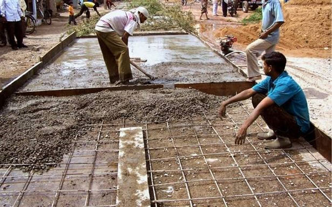
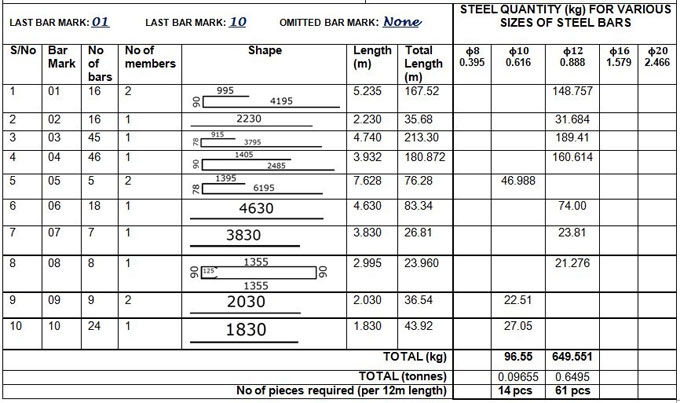
Bar bending schedule is an important structural working document that rightly gives the disposition, bending shape, total length, and quantity of all the reinforcements that have been provided in a structural drawing. It is often provided in a separate sheet (usually A4 paper) from the structural drawing. The bar marks from structural detailing drawing are directly transferred to the bar bending schedule. We normally quantify reinforcements based on their total mass in tonnes or kilograms. For smaller projects, you can quantify based on the length needed.
Unit mass of rebars
The unit mass of the reinforcements is obtained from the density of steel. The density of steel provided for this purpose is 7850 kg/m3.
Suppose, there is a bar with 12mm dia;
The area is calculated by (πd2)/4 = (π × 122)/4 = 113.097mm2 = 0.0001131m2
Based on a unit length of the bar, it is established that the volume of a metre length of the bar is 0.0001131m3.
Density = Mass/Volume = 7850 kg/m3 = Mass/0.0001131
So, the unit mass of 12mm bar = 7850 × 0.0001131 = 0.888 kg/m
So, for any diameter of bar;
Basic weight = 0.00785 kg/mm2 per metre
Weight per metre = 0.006165 ϕ2 kg
Weight per mm2 at spacing s(mm) = 6.165ϕ2/s kg
Here; ϕ denotes diameter of bar in millimetres Bending Shapes There exist some basic standard shapes with specific shape codes in the code of practice. The length of reinforcement bars can be determined with the following relation;
Length of bar = Effective Length + Width of Support – Concrete cover (s) – Tolerances The standard values of tolerances (deductions) are provided in the table below;
To get more details, go through the following linkstructville.com
~~~~~~~~~~~~~~~~~~~~~~~~ Published By Rajib Dey www.constructioncost.co ~~~~~~~~~~~~~~~~~~~~~~~~
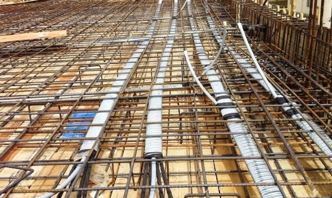
In this construction video tutorial, you will learn how post tension RCC slabs are built up as well as how post tensioning is performed and benefits of post tensioning process. POST TENSION SLAB: It refers to the slab that is tensioned as soon as the slab is developed. Reinforcement is arranged to avoid the compression. In Post tension slab, cables or steel tendons are utilized to substitute the reinforcement. Post-tensioning offers a solution to get rid of the natural weakness of concrete in tension as well as optimize its strength in compression. In concrete structures, this is obtained by arranging high-tensile steel tendons/cables in the element prior to start the casting. If the concrete attains the required strength, the tendons are pulled with special hydraulic jacks and retained in tension with specially designed anchorages which are attached at each end of the tendon. It creates compression at the edge of the structural member that increases the strength of the concrete for resisting tension stresses. If tendons are correctly curved to a specific profile, they will exert, other than compression at the perimeter, a useful ascendant set of forces (load balancing forces) that will neutralize applied loads, alleviating the structure from a portion of gravity effects. In this type of concrete slab, cables are affixed in place of reinforcement. In Steel reinforcement the gapping among bars is 4inch to 6inch while in Post tension slab the gapping is in excess of 2m. Go through the following video tutorial, to get more details on post tension slab.
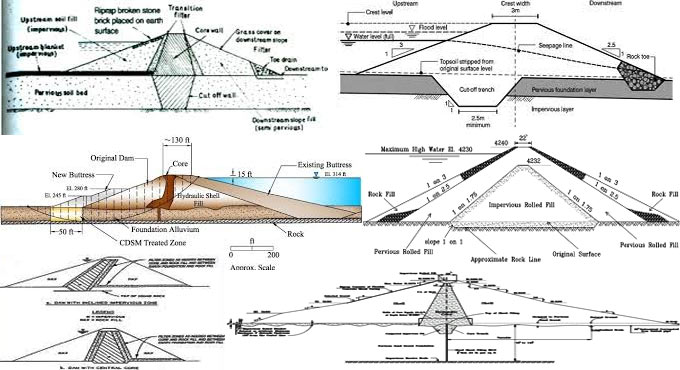
Now-a-days soil cement as a facing material for earthfill dams is considered very cost-effective where proper riprap is unavailable near the site. A fairly rigid foundation is suitable in order that deformation after disposition of soil-cement is not vital; however, no uncommon design features should be integrated into the embankment. Normal embankment construction methods are followed, with perhaps proper precaution to make sure a minimum of embankment consolidation and foundation settlement once the construction is completed. The soil-cement is normally arranged and compacted in stair-step horizontal layers. It provides greater construction efficiency and operational potency. With standard embankment slopes of 2:1 and 4:1, a horizontal layer with 8 feet width will set least protective thicknesses of about 2 and 3l/2 feet correspondingly, measured normal to the slope. It starts at the lowest layer of soil-cement, each subsequent layer is stepped back a distance equivalent to the product of the compacted layer thickness in feet times the embankment slope. As for instance, if the compacted thickness is 6 inches and the slope is 2:1, the step back is = 0.5(2) = 1 foot. The normal compacted layer thickness is 6 inches. Soil-cement layers of this dimension is positioned efficiently and compressed with standard highway equipment. A plating system that develops a single soil-cement layer parallel to the slope is often applied in less critical areas for slope protection. If the soil-cement facing does not start at natural ground level, the lower part of the embankment should remain on a flatter slope than the part safeguarded by the soil-cement; or a beam is arranged at the lowest elevation of the facing. It is necessary that the soil-cement expand underneath the minimum water level and over the maximum water level. The top of the facing should contain a freeboard allowance of minimum 1.2 times the projected maximum wave height, or 5 feet, whichever is higher. The edges of the finished soil-cement layers should not be cropped since the rounded starstep effect allows retard wave runup. Soil-cement is produced with different types of soils. The main standard for finding out the soil type is gradation. Coarse sandy or gravelly soils having about 10 to 25 percent material passing the No.200 sieve are perfect (American Society for Testing and Materials Standard Sieve Series). These soils are sufficiently stabilized with from 3 to 5 sacks of cement per cubic yard of compacted soil cement. Standard compaction and placement control for soil-cement is recommended. If the amount of material smaller than the No.200 sieve surpasses 35 percent, some effort to determine a coarse material is appropriate from a processing cost standpoint. Soils with 50 percent or more material passing the No.200 sieve are not suggested for being applied in their natural state. To get more details, go through the following linkaboutcivil.org
~~~~~~~~~~~~~~~~~~~~~~~~
Published By
Rajib Dey
www.constructioncost.co
~~~~~~~~~~~~~~~~~~~~~~~~
Segregation means the partition of course materials (cement, sand, aggregates) from other mass. When the water quantity in the concrete mix is increased, the greater sized aggregates are detached thus results in segregation. Therefore, concrete should be free from segregation as concrete not only gets weak but lack of consistency also brings unwanted properties in the hardened state. The segregation can be avoided with the choice of proper grading and careful handling.
Reasons for segregation :
Carrying concrete mixes for long distance.
Imperfectly proportioned mix where adequate matrix does not exist to unite the aggregates.
Dropping concrete from height places (underground foundation & rafts).
Vibrating concrete for long time.
Segregation is available in two types - Initially (in too dry mixes), the coarse aggregate is segregated or settling down from the rest of the matrix, secondly ( in too wet mixes ), the paste or matrix is detached away from coarse aggregate. In case of segregation, remixing for a short time may transform concrete again homogeneous.
The following precautions should be taken to get rid of concrete segregation :-
The concrete mix should be perfectly designed with best possible quantity of water i.e. not too wet nor too dry.
The proportion of the mix should be correct.
Ensure the concrete is mixed perfectly at the proper speed in a transit mixture for minimum two minutes.
Concrete should not become excessively wet or dry.
Refrain from arranging concrete from long height.
There should be proper transportation of concrete through shortest route.
Air entraining admixture and pozzolanic materials should be used in mix.
Select coarse and fine aggregate with approach specific gravity.
The vibrator should be used for exact time period (not too long or short).
Don’t permit concrete to flow.
The formwork should be firm.
The formwork should not be vibrated.
Video Source: Civil Engineers
~~~~~~~~~~~~~~~~~~~~~~~~
Published By
Rajib Dey
www.constructioncost.co
~~~~~~~~~~~~~~~~~~~~~~~~