adsense analytic

Showing posts with label Concrete Slab Design. Show all posts

Monday, July 16, 2018

Bar Bending Schedule For Floor Slabs

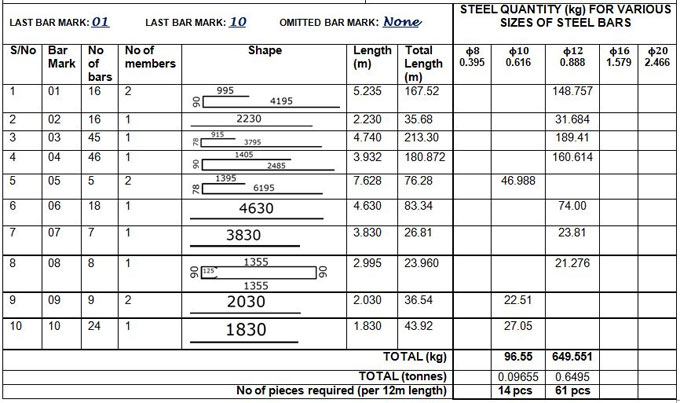
Bar bending schedule is an important structural working document that rightly gives the disposition, bending shape, total length, and quantity of all the reinforcements that have been provided in a structural drawing.

It is often provided in a separate sheet (usually A4 paper) from the structural drawing.

The bar marks from structural detailing drawing are directly transferred to the bar bending schedule. We normally quantify reinforcements based on their total mass in tonnes or kilograms. For smaller projects, you can quantify based on the length needed.
Unit mass of rebars
The unit mass of the reinforcements is obtained from the density of steel. The density of steel provided for this purpose is 7850 kg/m3.
Suppose, there is a bar with 12mm dia;
The area is calculated by (πd2)/4 = (π × 122)/4 = 113.097mm2 = 0.0001131m2
Based on a unit length of the bar, it is established that the volume of a metre length of the bar is 0.0001131m3.
Density = Mass/Volume = 7850 kg/m3 = Mass/0.0001131
So, the unit mass of 12mm bar = 7850 × 0.0001131 = 0.888 kg/m
So, for any diameter of bar;
Basic weight = 0.00785 kg/mm2 per metre
Weight per metre = 0.006165 ϕ2 kg
Weight per mm2 at spacing s(mm) = 6.165ϕ2/s kg
Here;
ϕ denotes diameter of bar in millimetres
Bending Shapes
There exist some basic standard shapes with specific shape codes in the code of practice.
The length of reinforcement bars can be determined with the following relation;
Length of bar = Effective Length + Width of Support – Concrete cover (s) – Tolerances
The standard values of tolerances (deductions) are provided in the table below;
To get more details, go through the following link structville.com
Bar Bending Schedule For Floor Slabs

~~~~~~~~~~~~~~~~~~~~~~~~
Published By
Rajib Dey
www.constructioncost.co
~~~~~~~~~~~~~~~~~~~~~~~~

Wednesday, September 6, 2017

RetainWall version 2.60 – A powerful software for designing a concrete or masonry retaining wall

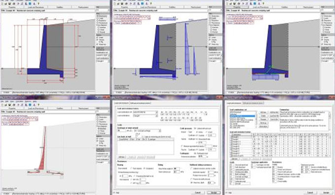
Dhani Irwanto has developed RetainWall. It is an exclusive software that can be used for making the design of a concrete or masonry retaining wall. The wall may preserve soil or other granular material.
It examines the strength of the wall on the basis of the loads and resistances, and leads to bearing pressure, sliding, overturning and rotational stabilities. Loads which operate on the wall may include self weight, soil pressure, water pressure, live and seismic loads.

Resistances may contain base friction and cohesion, passive earth pressure, other structures or a shear key. Load and resistance factor design (LRFD) mode can be employed. If the wall is a reinforced concrete structure, the software can also produce the reinforcement design for any reinforced concrete structure wall. Besides, there is a soil pressure calculator.
This user-friendly application provides on-screen trial-and-error method and instant solution for the design. With it, any designer will be able to design the wall swiftly. Complete outputs are visible on screen or printed.
The software starts it’s operation by clicking on the specified dimensions to produce the initial dimensioning of the wall, earth surface and water levels. After that, it enters material properties of the wall, soil, water and reinforcement bars. Provided external loads contain surcharge load, seismic load as a horizontal seismic coefficient and any concentrated loads implemented on the wall if necessary. Load and resistance factors combinations are easily selected. Results of the wall stability are gained immediately. If satisfactory result is not obtained, then another trial can be produced instantly. You can also choose from options to use or not to use water, seismic or ashear key. The final results can also be printed.
The reinforced concrete design can be made instantly by applying the internal forces of the wall. It only needs bar diameters and spacings of the reinforcements.
RetainWall is compatible with metric, SI and British unit systems.
Given below, some exclusive features of the software :-
a. Ability to design Load and resistance factors.
b. Apply load and resistance factors combinations from AASHTO LRFD 2007, ACI 318-08 and IBC 2006.
c. Load and resistance factors editor to change or generate new combinations
d. Concrete reinforcement design from ACI 318-08.
e. Force diagrams (moment, shear and normal) for every combination.
f. Loads, resistances and reactions diagrams for every combination.
g. Wall stabilities (bearing, sliding, overturning, rotation) for every combination.
h. Workout nominal soil bearing resistance by applying theoretical or semi empirical methods.
i. Ability to select active or at rest soil pressures.
j. Ability to select elastic (rock) or plastic (soil) bearing pressures.
k. Ability to enter user's soil pressure coefficients.
l. Reinforcement design for upper stem, lower stem, toe and heel.
m. Unit systems, properties, load and resistance factors, reinforcement design method, and page setup from last editing which turn out to be the default for new design.
n. Ability to include other loads on wall.
o. Offer stability resistances from a shear key, toe passive soil pressure, adjacent structure, anchors or piles.
p. Enable or disable a shear key, water or seismic.
q. Various types of units of measurements like metric, SI and British unit systems are supported.
r. Easy, clear, quick and simple software operation.
s. Help facilities, can be printed to produce manual.

Click on the following link to download a trial version RetainWall version 2.60

RetainWall version 2.60 – A powerful software for designing a concrete or masonry retaining wall


~~~~~~~~~~~~~~~~~~~~~~
Published By
Rajib Dey
www.constructioncost.co
~~~~~~~~~~~~~~~~~~~~~~

Wednesday, May 24, 2017

Overview of Peikko DSA Punching Reinforcement System for Cast-in-Place Concrete

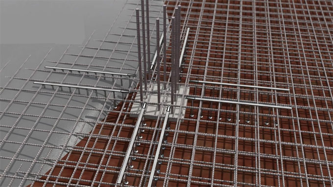
This construction video tutorial provides the demonstration Peikko DSA Punching Reinforcement. It belongs to a Transverse Reinforcement System for Cast-in-Place Concrete. It is specifically designed to improve the strength of punching shear concerning elevated concrete slabs and slabs on grade devoid of raising their thickness.

DSA rails consist of steel double-headed DSA Studs welded to a steel shape. The steel shape ensures the exact spacing and placing of the studs throughout their set up in concrete as per ASTM-A1044 standard. It should be used for both top and bottom installation.
Peikko DSA Punching Reinforcement offers an easy and consistent solution toward punching and shear failure which may happen in elevated concrete slabs, slabs on grade and footings.
If DSA Punching Reinforcement is applied in elevated slabs like reinforced concrete slabs or post-tensioned slabs, DSA Punching Reinforcement system disregards the requirement for column capitals. Therefore, forming and concrete costs are minimized significantly.
DSA reinforced cast-in-place elevated slabs are designed slimmer to minimize the entire construction height. It leads to huge savings in construction and running costs. The DSA system also provides a ceiling with uninterrupted clearance facilitating adaptability and simplicity of planning and installation of building services.
The fabrication process for DSA studs is done with low carbon steel grades C1010 through C1020. DSA Punching Reinforcement system adheres to the standard specification for steel stud assemblies for the shear reinforcement of concrete ASTM A-1044. It should be designed according to ACI 318-14 and CSA A23.3-14 which make it relevant in North America and Middle East.
Punching Reinforcement systems are also employed in foundations to curtail the thickness of footings, pile caps and slabs on grade. Other applications range from DSA rails are utilized as shear reinforcement in beams, walls and other concrete elements.


To get more information, click on the following link. www.peikkousa.com

Overview of Peikko DSA Punching Reinforcement System for Cast-in-Place Concrete

~~~~~~~~~~~~~~~~~~~~~~~~
Published By
Rajib Dey
www.constructioncost.co
~~~~~~~~~~~~~~~~~~~~~~~~

Friday, May 19, 2017

Analysis and Design of Concrete Retaining Wall

Concrete Retaining Wall Design: Before starting, initially, we should verify the constancy of the retaining wall. Besides, verification should be done for overturning and sliding prior to continue with the design.
The bearing under the foundation should also be examined. If the soil provides support to the wall, bearing pressure below the foundation of wall shall be under the acceptable bearing capacity.
To start with, you should inspect the retaining wall and determine the bending moments and shear forces with the use of an analysis software like SAP2000 or PROKON or any other software or with calculations by hand. If there are dissimilarities like steps in the retaining wall and the emphasis is given on stress variation of the wall, you can utilize software like SAP2000 or ANSIS.
Calculations by hand can be performed for basic retaining walls which do not contain lots of complications. As for instance, cantilever retaining wall is examined by making its behavior simple. You can imagine the boundary condition "fixed" at base to get the bending moments and shear forces of the wall. Once the wall forces are detected, you can get the forces of the base of the wall. The most suitable process will be applying a software to locate the bending moments and shear forces.

To know about the complete process, click on the following link. structuraldesignbs.blogspot.in

Analysis and Design of Concrete Retaining Wall

~~~~~~~~~~~~~~~~~~~~~~~~
Published By
Rajib Dey
www.constructioncost.co
~~~~~~~~~~~~~~~~~~~~~~~~

Tuesday, May 9, 2017

Some useful construction tips on concrete mix design

This construction video tutorial focuses on concrete mix design. In this video grades are taken as M 7.5, M10, M15, M20 and mix ratios for cement, sand and aggregate are taken as 1:4:8, 1:3:6, 1:2:4, 1:1.5:3. The amount of water is required for amalgamating concrete in 50 kg cement.

Concrete mix design refers to the method of choosing the appropriate components (cement, sand and coarse aggregates) as well as their relevant proportions with the purpose of developing concrete by maintaining specific minimum strength & durability.
Objective of mix design
To make sure that the optimal ratios of the constituent materials is maintained to satisfy the need of the structure.
To obtain the preferred minimum strength in the hardened stage.


To obtain the needed minimum strength in the hardened stage.
To obtain the preferred strength in the specified environment conditions
To form concrete as inexpensively as possible.

Read more

~~~~~~~~~~~~~~~~~~~~~~~~
Published By
Rajib Dey
www.constructioncost.co

~~~~~~~~~~~~~~~~~~~~~~~~