adsense analytic

Showing posts with label construction design. Show all posts

Tuesday, February 12, 2019

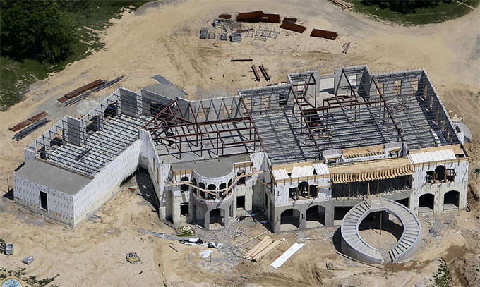
Some outstanding ideas to design your home with Concrete

Besides, concrete, other materials like steel, fibre, plastic, glass, wood and other superior materials can also be used together with concrete to build up homes. Now-a-days, concrete is extensively utilized for the construction of commercial, residential, institutional, and industrial buildings due to it’s adaptability, cost-effectiveness and the easy accessibility of raw materials for production.

In recent times, concrete home construction is gaining popularity because of the factors like sustainability, green building, disaster resistance, energy conservation, and safety. To satisfy these requirements efficiently, the engineers offer some unique design ideas.

Concrete Home Design Ideas: Designers have provided different types of design ideas for the construction of concrete homes owing to its versatility and easy accessibility of construction materials. Motivations that put into effect or head over to new design ideas are dissimilar, as for example, some design ideas get inspiration from nature while some from energy efficiency, aesthetics, sustainability, and recycling materials.

Advantages of Concrete Homes:

1. Stable
One of the most outstanding properties of concrete is its strength which offers comfortable shelter from inclement weather, and minimizes property damage while safeguarding from severe weather and natural disasters.


2. Long-lasting
Future maintenance is not required for home as a result the construction cost is reduced significantly.


3. Adaptable
Concrete is a multifaceted material from which any shape and form can be developed. This features facilitates the designers to produce innovative designs on the basis of the demand of client and situations under considerations.


4. Eco-Friendly
The materials necessary to develop concrete are accessible in local areas. Recycled materials like recycled aggregate, pozzolanic cementitious materials like fly ash and silica fumes are utilized to build up concrete.


It results in decreasing CO2 emission throughout cement production since a smaller quantity of cement is required for production.

5. Advantages throughout life-cycle of the Structure
Concrete homes offer various advantages and benefits all through their life span. As for example, chills inside area of the house and consequently curtail energy consumption, and give protection against disasters like fire; hurricane; earthquake; and flood.


Besides, concrete contains low volatile organic compound and it does not impact indoor air quality. Finally, it can be recycled to develop recycled concrete aggregate.

To get some of the most outstanding and award-winning design ideas for construction of concrete homes, click on the following link theconstructor.org
Some outstanding ideas to design your home with Concrete

~~~~~~~~~~~~~~~~~~~~~~~~~~
Published By
Rajib Dey
www.constructioncost.co
~~~~~~~~~~~~~~~~~~~~~~~~~~
Wednesday, September 6, 2017

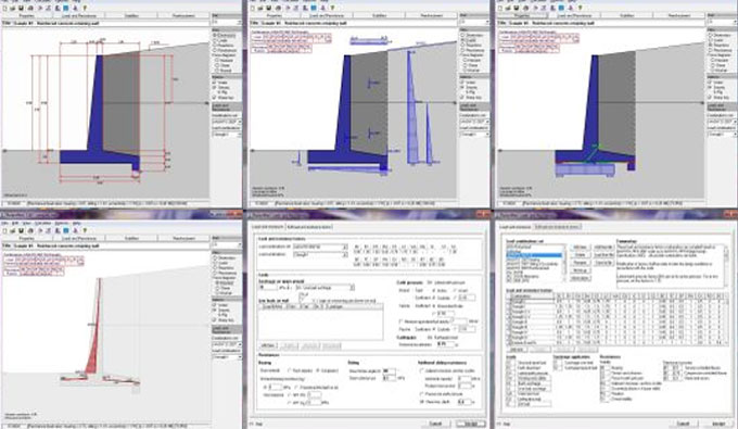
RetainWall version 2.60 – A powerful software for designing a concrete or masonry retaining wall

Dhani Irwanto has developed RetainWall. It is an exclusive software that can be used for making the design of a concrete or masonry retaining wall. The wall may preserve soil or other granular material.
It examines the strength of the wall on the basis of the loads and resistances, and leads to bearing pressure, sliding, overturning and rotational stabilities. Loads which operate on the wall may include self weight, soil pressure, water pressure, live and seismic loads.

Resistances may contain base friction and cohesion, passive earth pressure, other structures or a shear key. Load and resistance factor design (LRFD) mode can be employed. If the wall is a reinforced concrete structure, the software can also produce the reinforcement design for any reinforced concrete structure wall. Besides, there is a soil pressure calculator.
This user-friendly application provides on-screen trial-and-error method and instant solution for the design. With it, any designer will be able to design the wall swiftly. Complete outputs are visible on screen or printed.
The software starts it’s operation by clicking on the specified dimensions to produce the initial dimensioning of the wall, earth surface and water levels. After that, it enters material properties of the wall, soil, water and reinforcement bars. Provided external loads contain surcharge load, seismic load as a horizontal seismic coefficient and any concentrated loads implemented on the wall if necessary. Load and resistance factors combinations are easily selected. Results of the wall stability are gained immediately. If satisfactory result is not obtained, then another trial can be produced instantly. You can also choose from options to use or not to use water, seismic or ashear key. The final results can also be printed.
The reinforced concrete design can be made instantly by applying the internal forces of the wall. It only needs bar diameters and spacings of the reinforcements.
RetainWall is compatible with metric, SI and British unit systems.
Given below, some exclusive features of the software :-
a. Ability to design Load and resistance factors.
b. Apply load and resistance factors combinations from AASHTO LRFD 2007, ACI 318-08 and IBC 2006.
c. Load and resistance factors editor to change or generate new combinations
d. Concrete reinforcement design from ACI 318-08.
e. Force diagrams (moment, shear and normal) for every combination.
f. Loads, resistances and reactions diagrams for every combination.
g. Wall stabilities (bearing, sliding, overturning, rotation) for every combination.
h. Workout nominal soil bearing resistance by applying theoretical or semi empirical methods.
i. Ability to select active or at rest soil pressures.
j. Ability to select elastic (rock) or plastic (soil) bearing pressures.
k. Ability to enter user's soil pressure coefficients.
l. Reinforcement design for upper stem, lower stem, toe and heel.
m. Unit systems, properties, load and resistance factors, reinforcement design method, and page setup from last editing which turn out to be the default for new design.
n. Ability to include other loads on wall.
o. Offer stability resistances from a shear key, toe passive soil pressure, adjacent structure, anchors or piles.
p. Enable or disable a shear key, water or seismic.
q. Various types of units of measurements like metric, SI and British unit systems are supported.
r. Easy, clear, quick and simple software operation.
s. Help facilities, can be printed to produce manual.

Click on the following link to download a trial version RetainWall version 2.60

RetainWall version 2.60 – A powerful software for designing a concrete or masonry retaining wall


~~~~~~~~~~~~~~~~~~~~~~
Published By
Rajib Dey
www.constructioncost.co
~~~~~~~~~~~~~~~~~~~~~~

Tuesday, August 22, 2017

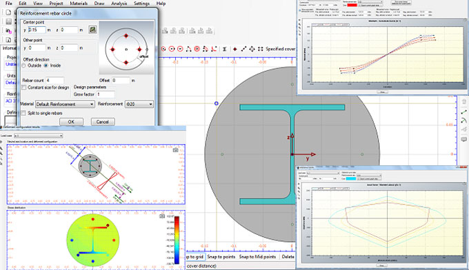
Cross Section Analysis & Design is a powerful construction program for analysis & design of structural cross section

Cross Section Analysis & Design (most recognized software for structural uses in America, Europe, Asia and Australia) refers to a robust application that can be applied for computing an extensive range of cross section, along with the formation of design for reinforced concrete sections (rebar calculator).
The resultant cross sections are simple or composite and can comprise of one or more geometric entities (rectangles, polygons, circles, arcs etc.). With the multipurpose featured user interface, it is possible to draw the geometry of the cross section easily.

The user will be able to import standard steel sections out of a complete shape library in relation to all significant codes (AISC, Australian-New Zealand, BS, Chinese, European, Indian, Aluminum etc.)
The shape, materials or loads of a section are free from any restriction, because the program can deal with any random cross section under biaxial bending and axial loads (Mx,My,P). The program has the ability to work out all sectional properties, plot Moment – Curvature and Interaction diagrams as well as calculate the location of the neutral axis under specified sets of biaxial loads and outline the equivalent strain diagrams along with the consequential stress contours. Based on the position of the neutral axis plane on the section, these items can also be calculated.
Besides, the program is adhered to the following codes regarding reinforced concrete sections: AASHTO, UBC, AS 3600, IS 456, ACI 318, BS 8110, CSA A233, EC2, NZS 3101, CP 65.
The user will be able to produce a reinforcement design on the basis of the codes given above, outline the equivalent interaction diagrams etc., or examine a specified reinforcement pattern under the given load cases with some simple mouse clicks.
With Analysis Parameters Sets, the stress – strain curves of concrete, reinforcement and other materials are indicated parametrically. Every load case is allotted with an Analysis Parameters Set, so that estimations can be made for various design situations, like Ultimate/Serviceability or custom defined Limit States, with an automatic adjustment of the material properties, safety factors etc. As for example, while going to select the default ULS Parameters Set, the concrete curve should have been rectangular and its tensile strength should not be taken into account. Alternatively, the default SLS Parameters Set, applies a hyperbolic stress-strain curve for concrete considering its tensile strength. Here, the safety factors are automatically settled as 1.0. The user has the ability to directly modify these parameters.
An extensive material library exists along with almost all concrete/reinforcement material specifications. Besides, concrete and reinforcement materials, the user can also state custom linear, bilinear, trilinear parabolic or completely general materials.
The program supports Windows XP/Vista/7/8/8.1/10.

For more information, click on the following link engissol.com

Cross Section Analysis & Design is a powerful construction program for analysis & design of structural cross section


~~~~~~~~~~~~~~~~~~~~~~
Published By
Rajib Dey
www.constructioncost.co
~~~~~~~~~~~~~~~~~~~~~~

Wednesday, July 12, 2017

Foundation3D – A powerful construction tool for footing analysis and design

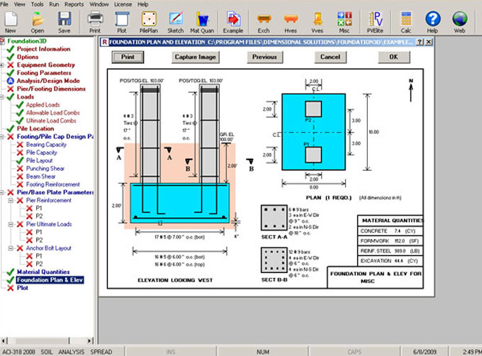
Foundation3D is a powerful tool that can be used for analyzing and designing spread and combined footing. The design of soil or pile supported foundation can be completed without any difficulty.
This tool is best suited for for creating the design of foundations for industrial equipment like horizontal exchangers and vessels, vertical vessels or towers, pipe racks and other plant supports.

By creating foundation design automatically, Foundation3D can constantly fulfill or outdo your project schedule requirements. Foundation3D facilitates to considerably enhance your productivity at each phase of your project ranging from equipment-specific automated load calculations to generating design sketches.
MAIN FEATURES:
• International Design Codes: Compatible with various international concrete design codes to finish the global projects successfully.
• User Defined Parameters: There are various customizable design options like concrete cover, pile arrangement and lots others to facilitate fulfilling different types of project specifications.
• Load Generation: Computes different types of equipment loads along with wind loads instantly and precisely to save significant times for load calculation.
• Load Cases and Combinations: Produces load cases and combinations for equipment foundation design which are mostly utilized and reduce major design time
• Soil/Pile Supported Designs: Accomplishes both soil and pile supported foundation designs in an collaborative surrounding facilitating you to explore with various “what-if” scenarios for getting best solution
• Analysis/Design Modes: Provides supports to both analysis and design modes for successful execution of your grass-roots or revamp projects, minimizing the total cost of ownership
• Numerous Foundation Components Design: Accomplishes the design process of several elements concerning a foundation like pedestals and footing, saving you the cost of learning multiple software solutions
• Rebar Layouts: Produces the layouts of rebar in pedestals and footings with customization options
• Material Quantities: Creates the material quantities to produce perfect cost estimates to your customers each time, at each stage of the project
• Detailed Design Sketches: Creates a detailed design sketch along with foundation plan, elevation, and sections, facilitating you to sum up the finalized design efficiently

• 2D Drawings: Collaborates with most recognized CAD engines to deliver 2D construction drawings, allowing you to control your design-drawing environment and human resources competently
• 3D Models: Collaborates with robust modeling tools to produce 3D models of the completed foundation design, facilitating you to fulfill or outdo compressed, variable project schedule requirements
• Multiple Reporting Options: Produces various types of customizable reports for your internal or client requirements
• Import Wizard: Imports support geometry and reactions from any superstructure software solution to execute foundation design instantly, enhancing your productivity.

Foundation3D – A powerful construction tool for footing analysis and design


~~~~~~~~~~~~~~~~~~~~~~~~
Published By
Rajib Dey
www.constructioncost.co
~~~~~~~~~~~~~~~~~~~~~~~~

Friday, June 30, 2017

How to design the reinforced concrete wall

You have to design the Reinforced concrete wall similar to a compression member. Reinforced concrete wall is suitable when there are no beams and load transmitted from the slab is massive or the density of the masonry wall is restrained.
RCC Wall is segregated as follow:
• Plain concrete wall, when rein. < 0.4%
• Reinforced concrete wall, when rein. > 0.4%

Load from slab is transmitted as axial load to wall. When depth is greater, it is known as RC wall. Design is identical to a RC column, breadth is similar to the density of wall and depth is equivalent to 1m. The design of RCC Wall is based on the following factors.
• Axially loaded wall
• Axially loaded with uniaxial bending
Categorization of concrete walls:
1. Plain concrete wall
2. Reinforced concrete wall
Under plain concrete wall, the reinforcement included is under 0.4% of c/s. In reinforced concrete wall, the proportion of employed steel is in excess of 0.4% and is designed in the same way as reinforced concrete columns. Slenderness ratio is equivalent to minimum of (l/t or h/t), where, l denotes effective length of wall, h stands for effective height of wall, t stands for thickness of wall. When < 12, the wall becomes short and if > 12, the wall becomes slender.
Braced and Unbraced Concrete Walls:
Braced: If cross walls are arranged for the walls so as to they can bear lateral load and 2.5% of vertical load, then the wall is defined as braced. If not, the wall is called as unbraced wall.
Note: Other walls under special cases are,
i) Cantilever wall
ii) Shear walls – To withstand lateral loads [Handle flexure created because of lateral loading on the structure, depth is allowed along the transverse direction]


To learn the detail process, watch the following link theconstructor.orgn

How to design the reinforced concrete wall


~~~~~~~~~~~~~~~~~~~~~~~~
Published By
Rajib Dey
www.constructioncost.co
~~~~~~~~~~~~~~~~~~~~~~~~

Monday, November 7, 2016

How to create the design of simply supported steel beam

This construction video is created for educational purpose.The tutorial will be a complement to the "Mechanics of Materials" course conducted at the Colorado School of Mines.By watching this construction video tutorial, one can learn how to create the design efficiently for simply supported steel beam.

Download Design of a Steel Beam in pdf


~~~~~~~~~~~~~~~~~~~~~
Published By
Rajib Dey
~~~~~~~~~~~~~~~~~~~~~

Monday, June 27, 2016

Construction Master 5 – A Useful Construction Tool For Building Professionals

This construction video is based on Construction Master 5 contractor calculator. By watching this video one can learn how 5’s stair function of construction master can save significant time for building professionals for computation and stair table lookups.

Construction Master 5 contractor calculator's in-built stair layout key can provide streamlined solution to develop your next stairs together with number of risers, riser height, number of treads, tread widths, stringer length, angle of incline and total run of the stairs.

Get trained how to utilize this construction math power tool to execute all your design, estimating and jobsite calculations easily, instantly and perfectly to make your productivity and profitability better.

This construction calculator offers the following features :-

Dimensional Math and Conversions

• Performs and transforms among building dimensional formats: Yards, Feet-Inch-Fractions, Decimal Feet-Inches and Metric – together with Area and Volume

• Detect Weight per Volume Committed Functions

• Workout Stair for Risers, Treads, Stringer Length and Incline Angle; shows Run and Rise

• Custom Rafter Function offers Common Rafters, Regular and Irregular Hips, Valleys and Jacks. Jack Rafter feature offers comprehensive solutions for Normal and Asymmetrical Pitch roofs. Exposes On-center spacing.

• Solutions for Circles, Arcs, Columns, Pillars, Windows, Post-holes and more

• Rake-Wall function defines Stud Length for any On-center Spacing, in Ascending or Descending order

• Board Feet Lumber calculation


To get more information, visit this link


~~~~~~~~~~~~~~~~~~~~
Published By
Rajib Dey
~~~~~~~~~~~~~~~~~~~~

Saturday, May 21, 2016

REBARS Is A Spreadsheet Program To Determine Reinforcing Bar Development And Splice Lengths For Steel Reinforcement

"REBARS" is a MS-Excel based spreadsheet program useful for ascertaining reinforcing bar development and splice lengths specially, the development lengths and splice lengths for straight bars in tension as well as compression. Besides, the development length for standard hook bars is calculated. The provisions for development and splice lengths are contained in high seismic risk applications by adhering ACI 318-05. There also exists a worksheet that consists of reinforcing bar data tables. This version is developed on the basis of the ACI 318-05 Code.

Program Assumptions and Limitations:

1. This program abides by the methods and guidelines of the ACI 318-05 Building Code, Chapters 12 and 21.

2. The "Calc Development" worksheet, for a specified reinforcing bar size, establishes the straight development and splice lengths toward a "top" bar and an "other" bar in tension, the straight development and splice lengths for the bar in compression, and the tension development length of the bar as a standard hook, all at once. A comprehensive table of reinforcing bar development and splice lengths is also generated for #3 over #18 bars. 

3. The "Rebar Data" worksheet includes tables of reinforcing bar data having different bar properties, reinforcing bar areas on the basis of spacing, tension development and splice lengths for straight bars, tension development lengths for 90 degree standard hooks, tension lap splice criteria, compression development and splice lengths for straight bars, maximum spacing for column ties, and different plain welded wire fabric properties. 

4. This program covers several “comment boxes” which consist of diversified information along with clarifications of input or output items, equations applied, data tables, etc.

For more information, visit the link

REBARS is a spreadsheet program to determine reinforcing bar development and splice lengths for steel reinforcement
Image Courtesy : Engineersdaily

~~~~~~~~~~~~~~~~~~~~~
Published By
Rajib Dey
~~~~~~~~~~~~~~~~~~~~~

Thursday, November 26, 2015

Detailed Process for effective slab reinforcement

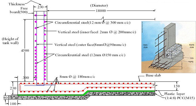
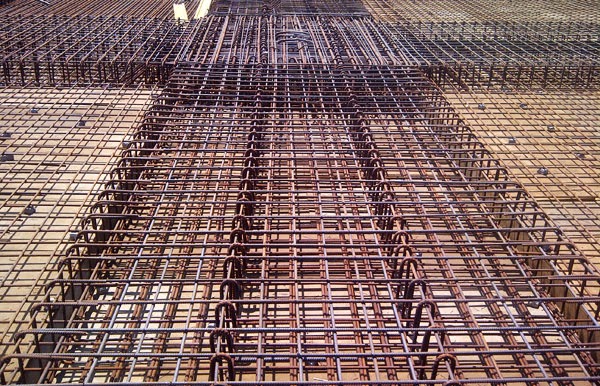
This construction video will highlight the detailed process for complicated slab reinforcement. All steel bars are connected following the design details. Here the concrete ratio is 1:2:4. This video is very useful for Civil Engineering students as well as various structural engineering professionals.

The slabs containing ratio of longer length to its shorter length (Ly/Lx) larger than 2 is known as one way slab or else as two way slab. In one way slab main reinforcement is equivalent to shorter direction and the reinforcement equivalent to longer direction is defined as distribution steel. In two way slab main reinforcement is rendered alongside both direction.

Detailing Requirements of RCC Slab as per IS456: 2000

a) Nominal Cover:
For Mild exposure – 20 mm
For Moderate exposure – 30 mm
However, if the diameter of bar is less than 12 mm, or cover may be decreased to 5 mm. Therefore for core reinforcement up to 12 mm diameter bar and for mild exposure, the nominal cover will be 15 mm.

b) Minimum reinforcement: The reinforcement in either direction in slab must not be lower than
• 0.15% concerning the total cross sectional area for Fe-250 steel
• 0.12% concerning the total cross-sectional area for Fe-415 & Fe-500 steel.

c) Spacing of bars: The utmost spacing of bars must not surpass
• Main Steel – 3d or 300 mm whichever is lesser.
• Distribution steel –5d or 450 mm whichever is lesser Where, ‘d’ denotes the operative depth of slab. Note: The least clear spacing of bars must not be lower than 75 mm (Preferably 100 mm) even if code does not suggest any value.

d) Maximum diameter of bar: The maximum diameter of bar in slab, must not surpass D/8, where D denotes the total thickness of slab.


~~~~~~~~~~~~~~~~~~~~~~
Published By
Rajib Dey
~~~~~~~~~~~~~~~~~~~~~~

Monday, September 28, 2015

How to design tank foundation with AFES foundation design software

This construction video provides brief guidelines for the design for tank foundations with AFES foundation design software. This video is very useful civil engineers.

AFES is a useful software designed for raft foundation. It consists of structural calculation report, construction drawing having bar schedule, material quantities and 3D CAD modeling.

It is used to create the design of equipment supports, steel structure and piperack foundations.

Storage Tank Foundation Design Guide


Tank Foundation Design

~~~~~~~~~~~~~~~~~~~~~~
Published By
Rajib Dey
~~~~~~~~~~~~~~~~~~~~~~

Wednesday, March 25, 2015

Download commercial line item cost breakdown spreadsheet

Download commercial line item cost breakdown spreadsheet
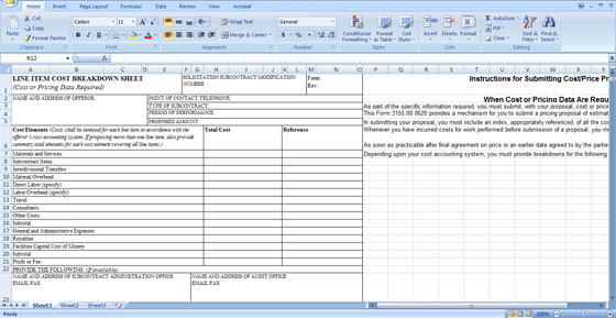
The spreadsheet represents complete breakdown of all expenses associated with the design and build process. Thisestimating spreadsheet includes the cost of materials & services, direct labor, other costs, royalties as well as facilities capital cost of money.

All costs are categorized for single line item compliant with the existing cost accounting system.

The spreadsheet must be submitted with your proposal as well as cost or pricingdata.

While tendering your proposal, you must encompass an index, properly referenced, concerning all the cost or pricing data and information affixing or acknowledged in the proposal.

Besides, you must explain any subsequent additions and/or amendments, up to the date of agreement on price, or an previous date settled mutually by the parties, on a additional index.


The spreadsheet represents complete breakdown of all expenses associated with the design and build process.


~~~~~~~~~~~~~~~~~~~
Published By
Rajib Dey
~~~~~~~~~~~~~~~~~~~

Tuesday, March 10, 2015

Download Civil Engineering Building Codes

Download Civil Engineering Building Codes
National Building code is actually bunch of rules which signifies the minimum standards of constructed as well as non-constructed objects. The main reason of building codes are to defend public health, safety and general welfare as they narrate to the construction and tenancy of buildings and structures.

The building code becomes law of an existing jurisdiction when officially enacted by the proper governmental or private authority. It has become law now.

Building codes square measure usually meant to be applied by architects, engineers, constructors and regulators however are used for numerous functions by safety inspectors, environmental scientists, land developers, subcontractors, and makers of building merchandise and materials, insurance firms.

The codes regulation the planning and construction of structures wherever adopted into law. Codes in developed western nations may be quite advanced and complete. They began in past and are developing ever since. Within the USA the most codes square measure the International industrial or Residential Code [ICC/IRC], electrical codes and plumbing, mechanical codes. Fifty states and also the District of Columbia have adopted the I-Codes at the state or territorial level.

Different codes could embody fireplace, health, transportation, producing, and different regulations/regulators/testers like UL; Underwriters Labs. In essence they're minimum standards of style and implementation.

Designers use ICC/IRC standards out of considerable reference books throughout style. Building departments review plans submitted to them before construction, issue permits and inspectors verify compliance to those standards at the positioning throughout construction.

There square measure usually further codes or sections of constant code that have a lot of specific needs that apply to dwellings or places of business and special construction objects like canopies, signs, pedestrian walkways, parking tons, and radio and TV antennas.
  • Download - National Building Code (Group 1)
  • Download - National Building Code (Group 2)
  • Download - National Building Code (Group 3)
  • Download - National Building Code (Group 4)
  • Download - National Building Code (Group 5)
National Building code is actually bunch of rules which signifies the minimum standards of constructed as well as non-constructed objects.

~~~~~~~~~~~~~~~~~~~~~~
Published By
Rajib Dey
~~~~~~~~~~~~~~~~~~~~~~