adsense analytic

Showing posts with label construction video. Show all posts

Tuesday, January 8, 2019

How to design a gabion retaining wall with Tekla Tedds

In this construction video tutorial, you will learn how to use Tekla Tedds for making calculations of gabion retaining wall analysis and design with adherence to the Eurocode to verify the strength of a gabion retaining wall from sliding overturning. Besides, it is also possible to find out the maximum and minimum base pressure underneath the wall.

A gabion retaining wall is built up with stacked stone-filled gabions which are attached together with wire. Gabion walls are generally battered (angled back towards the slope), or stepped back with the slope, in spite of stacked vertically. Besides, galvanized steel wire, PVC-coated and stainless steel wire are also utilized. This type of retaining wall is very effective for erosion control applications.

Tekla Tedds is a robust software that can be used to automate your tedious structural calculations. The users can select from one or more of the extensive calculation libraries.

The users will also be able to write their own, and generate professional documentation every time. It is also possible to integrate the structural calculations with 2D frame analysis.

The users can get access to the following extensive library of design modules.

• Loading - Seismic and Wind
• Analysis - Continuous Beams and Rolling Load
• Steel Design - Beams, Torsion, Columns
• Connections - Base Plates and Bolts


Tekla Tedds offer the following benefits :-

a. Get access of an expansive library of structural and civil calculations.
b. Employ a single solution for all common components & materials.
c. Reap benefits from a simple and intuitive interface.
d. Generate apparent calculations which can be simply analyzed.
e. Make comparison among various design options and create modifications instantly.
f. Create consistent documentation.
g. Improve your Quality Assurance processes.
h. Obtain new and improved calculations and code updates regularly.


To get online demonstration of Tekla Tedds, go through the following video tutorial.


Video Source: Tekla Software

~~~~~~~~~~~~~~~~~~~~~~~~~
Published By
Rajib Dey
www.constructioncost.co
~~~~~~~~~~~~~~~~~~~~~~~~~

Wednesday, December 26, 2018

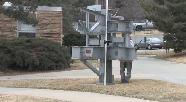
Uses and advantages of digital theodolite in surveying & engineering works

In this exclusive civil engineering tutorial, you will learn the step-by-step guidelines for employing digital theodolite.

The surveyors extensively use this tool for conducting topographic survey. With this tool, it is possible to determine both the horizontal and vertical angle. By combining with stateo techniques, it can work out the horizontal distances as well as differential elevations. It is a useful tool for surveying and engineering work.

Theodolites apply caged graduated circles and angular readings are captured with an internal magnifying optical system.

The theodolite comprises of a telescope that can be moved within two perpendicular axes- the horizontal axis, and the vertical axis. The telescope is fixed and an electronic readout screen is applied to demonstrate horizontal and vertical angles. Digital theodolites are user-friendly since the digital readouts substitute the conventional graduated circles and produce more precise readings.

Instructions for use :-

Label the point at which the theodolite is going to installed with a surveyor’s nail or a stake. This point is considered as the base for calculating the angles and distances.

Arrange the tripod. The height of the tripod should be kept in such a way so that the instrument (the theodolite) remain in eye-level. The centrally placed hole of the mounting plate should remain over the nail or stake.

Push the tripod legs into the ground with the brackets on the sides of each leg.

Fix the theodolite by positioning it on top of the tripod, and screw it in exact position with the mounting knob.

Calculate the height among the ground and the instrument. It should be applied as a reference to other stations.

The theodolite should leveled by altering the tripod legs and employing the bulls-eye level. The slight tuning is done with the leveling knobs to secure t it just right.

Alter the small sight (the vertical plummet) available on the bottom of the theodolite. The vertical plummet facilitates you to perform and make sure the instrument is situated over the nail or stake. Modify the plummet with the knobs on the bottom.

Point the crosshairs in the main scope at the point to be calculated. With the help of the locking knobs on the side of the theodolite, retain it aimed on the point. Record the horizontal and vertical angles with the viewing scope available on the theodolite’s side.

Benefits of applying a Theodolite

Given below, various advantages of Theodolites:


  1. Superior correctness.
  2. Internal magnifying optical system.
  3. Reading circles is more accurate as compared to other instruments.
  4. Electronic readings.
  5. Horizontal circles are rapidly zeroed or arranged with any other value.
  6. Horizontal circle readings are captured either to the left or right of zero.
  7. Repeat readings are not required.
  8. Suitable for both flat and sloped ground.
  9. Not affected with wind or other weather factors.
Uses and advantages of digital theodolite in surveying & engineering works

~~~~~~~~~~~~~~~~~~~~~~~~
Published By
Rajib Dey
www.constructioncost.co
~~~~~~~~~~~~~~~~~~~~~~~~

Friday, December 15, 2017

Some useful civil engineering notes

This construction video tutorial is very useful for civil engineering students as it contains 10 objective types of questions on civil engineering and their solutions.

Some of the sample questions & their answers are given below :-

As per pertinent IS code, the weight of the timber will be treated as perfect if there is 12% moisture content in it.

The strength of the timber will be optimal if applied load is parallel to grain.

A standard brick should not engross water by weight in excess of 20% (after immersed in water for 24 hours)

When ‘p’ denotes the standard consistency of cement, 0.85 percent water is utilized in performing the initial setting time test on cement.

The lime mortar is normally formed with hydraulic lime.

The compressive strength of a standard good 1:3 portland cement – sand mortar after the completion of 3 days of curing, should not be under 175 kg/cm2.

The split tensile strength of M15 grade concrete is 15 to 20% of its compressive strength.

For brief explanation, watch the following construction video tutorial.
Video SourceTechnical Atyachar


~~~~~~~~~~~~~~~~~~~~~~~~~
Published By
Rajib Dey
www.constructioncost.co
~~~~~~~~~~~~~~~~~~~~~~~~~
Thursday, December 14, 2017

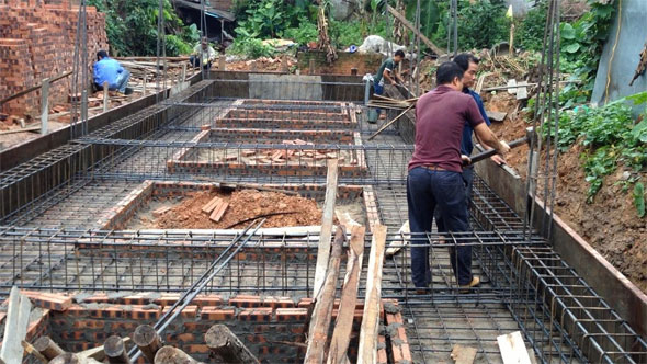
How to resolve issues prior to foundation design

To make a perfect foundation design, the following vital points should be taken into consideration:-

Make sure that the foundations are maintained as extremely shallow, suitable with atmospheric impacts and strength of the surface soil; specifically in flooded ground. Excavation in fatally flooded ground seems to be costly and slow.

Get rid of costly and complicated shuttering details specifically in hardened rafts. Proper care must be taken to examine the build aptitude.

The economics of the design can be significantly impacted with various factors like drop in the piling costs, upgrading in ground treatment, progression in soil mechanics, etc and various standard solutions are now obsolete. So, it is necessary to evaluate construction costs and methods on a regular basis.

Designers should be well versed with the presumptions provided in design, the inconsistency of ground conditions, infrequent inapplicability of refined soil analyses and the utility of construction.

Make proper evaluation to check the consistency of the soil.

Impact of construction on ground properties, i.e. vibration from piling, degradation of ground disclosed with excavation in unfavorable weather conditions, deduction of overburden, seasonal difference in the water-table, compaction of the ground through construction plant.

Impact of deviating shape, length and inflexibility of the foundation, and the requirement for movement and settlement joints.

Consequences on finished foundations with sulfate attack on concrete, ground movements because of frost heave, reducible clays, and the impacts of trees; also alterations in local environment, e.g. new construction, re-routing of heavy traffic, foundation of plant in adjacent factories inducing impact and vibration.

Rapid but costly construction may be more cost-effective as compared to low-cost but slow construction to clients requiring quick return on capital investment.


Impact of new foundation loading on existing nearby structures.
To get more information, go through the following construction video Civilblog.Org
How to resolve issues prior to foundation design
~~~~~~~~~~~~~~~~~~~~~~~~~
Published By
Rajib Dey
www.constructioncost.co
~~~~~~~~~~~~~~~~~~~~~~~~~
Friday, October 6, 2017

Some useful tips to select an authentic subcontractor in your construction project

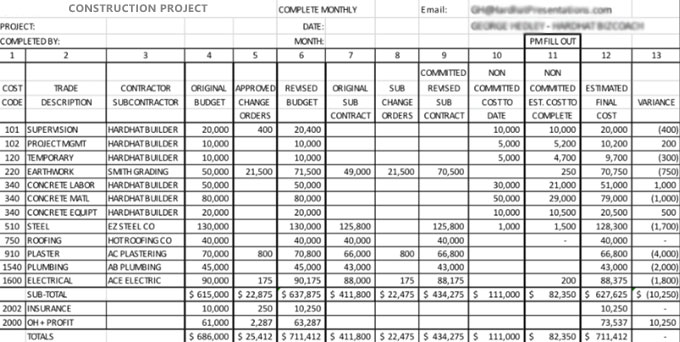
In a construction project there are specific areas where a contractor requires the assistance of an expert subcontractor. The objective of a general contractor is to handle the entire activities and performance among subcontractors.

A subcontractor can be shortlisted and selected on the basis of various points like past performances, financials and other important factors.

Given below, some valuable points based on which a perfect subcontractor can be selected for any construction project.
Before going to hire a subcontractor, it is necessary to assess the scope and project requirements perfectly. The service of a subcontractor is essential if the work remains beyond your expertise area or your resources are already settled to a diverse project for which it becomes difficult to accomplish the work with internal resources.
Prior to initiate the aptitude method, the general contractor should have to establish the size of the scope that is subcontracted out as well as the resources required to execute this work. It is vital to have clear idea on this part before implementation so as to get the proper bonding and insurance coverage for you and your subcontractor.
For lengthy subcontractor scope, it is required to undertake the steps like segregating the project into smaller parts or evaluating if it is the perfect project for your organization.
As soon as it is settled that it is appropriate for your organization, let's then proceed on to shortlist and choose the proper subcontractor.
Now if it is obligatory to hire a subcontractor with the purpose of supplementing your workforce, the general contractor should have to analyze the following areas:
• Safety
• Financials
• Staffing/Organigram
• Equipment
• Project Plan and Schedule
• Past Performances
• Comparable Projects
• Letter of Recommendation or References
• Project Cost and Payment Terms
A subcontractor should be capable of supplying this information as an answer to your RFP or throughout an RFQ process.
Safety performance is considered as one of the most crucial factors for a subcontractor at the time of qualifying. Ensure to evaluate the EMR rates, OSHA recordable, time loss owing to accidents/incidents. From a contractor point of view, you should assess who is their primary safety officer, its background, and credentials. As a contractor enquire of their safety plan and program and ensure to review it in order that it goes along with your safety expectations. Safety can also comprise of environmental response and methods upon emergencies and spills.
To gather more information on other crucial points, go through the following article thebalance.co
Some useful tips to select an authentic subcontractor in your construction project

Read more

~~~~~~~~~~~~~~~~~~~~~~~~
Published By
Rajib Dey
www.constructioncost.co
~~~~~~~~~~~~~~~~~~~~~~~~

Tuesday, June 13, 2017

Types of footings with diagrams

This is a nice video presentation from Parag Pal, the renowned civil engineer. In this video, Mr. Parag gives brief explanation about types of footings mostly utilized in construction. The types of footings range from isolated footings, mat footings, strap footings, combined footings. All the footings are demonstrated with their diagrams.
Footings are considered as the most vital parts in various foundations like bridges.
Isolated footings - Isolated footings are used in normal home, house constructions. When footing is arranged to provide support to a distinct column, it is known as “isolated footing”. It belongs to circular, square or rectangular slab having identical thickness.
Combined footings - When two or more columns in a straight line are passed on a single spread footing, it is known as a combined footing. It is generally utilized when the two column are very adjacent to each other so that their individual footings would coincide.
Strap footings - A strap footing is a constituent of the foundation of a building. It is one sort of combined footing that contains two or more column footings attached with a concrete beam. This type of beam is known as a strap beam.
Mat/Raft foundation or mat footings - A big, dense, generally reinforced concrete mat that delivers loads from various columns and walls, to the foundational rock or soil. It is called raft foundation.

For online demonstration, watch the following video.

Read more

~~~~~~~~~~~~~~~~~~~~~~~~
Published By
Rajib Dey
www.constructioncost.co

~~~~~~~~~~~~~~~~~~~~~~~~

Monday, June 12, 2017

How to generate bar bending schedule for the floor columns

This construction video will teach you how to produce bar bending schedule on the basis of the section drawing of floor column from ground floor to first floor.
Details of section drawing:
The height is given from ground floor to first floor as 3000 mm or 3 meter.
There are stirrups, main bars, beam and over lapping for column.
The overlapping for the column from 1st floor to 2nd floor is given as 50D.
The actual length of the column is given as 2543 mm i.e. stirrups will come up to this.
Stirrups Details:
The breadth of the column is 300 mm
The depth of the column is 450 mm
The cover is taken 40 mm on both sides
There are 6 main bars with 12 dia meter
There are stirrups of 8 mm with 100 mm spacing center to center

Based on the above, the calculation is made. Watch the following video to get the detailed calculation process.


Read continue

~~~~~~~~~~~~~~~~~~~~~~~~
Published By
Arka Roy
www.constructioncost.co

~~~~~~~~~~~~~~~~~~~~~~~~

Tuesday, May 30, 2017

Demonstration of center line method

This is another useful presentation from Parag Pal. The video shows the detailed information on Center Line Method.

Center line method is specifically applied for walls of equivalent cross sections. Here, the total centre line length is multiplied with breadth and depth of relevant item to determine the total quantity at once.

After the cross walls or partitions or verandah walls are attached with main wall, the centre line length becomes curtailed by half of breadth for every junction.


Such junction or joints should be cautiously taken into consideration at the time of measuring total centre line length. The method generates most precise estimates rapidly.


Read more

~~~~~~~~~~~~~~~~~~~~~~~~
Published By
Rajib Dey
www.constructioncost.co

~~~~~~~~~~~~~~~~~~~~~~~~

Wednesday, May 24, 2017

Overview of Peikko DSA Punching Reinforcement System for Cast-in-Place Concrete

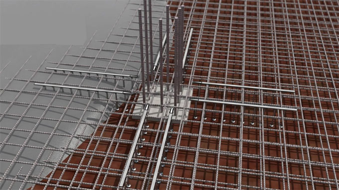
This construction video tutorial provides the demonstration Peikko DSA Punching Reinforcement. It belongs to a Transverse Reinforcement System for Cast-in-Place Concrete. It is specifically designed to improve the strength of punching shear concerning elevated concrete slabs and slabs on grade devoid of raising their thickness.

DSA rails consist of steel double-headed DSA Studs welded to a steel shape. The steel shape ensures the exact spacing and placing of the studs throughout their set up in concrete as per ASTM-A1044 standard. It should be used for both top and bottom installation.
Peikko DSA Punching Reinforcement offers an easy and consistent solution toward punching and shear failure which may happen in elevated concrete slabs, slabs on grade and footings.
If DSA Punching Reinforcement is applied in elevated slabs like reinforced concrete slabs or post-tensioned slabs, DSA Punching Reinforcement system disregards the requirement for column capitals. Therefore, forming and concrete costs are minimized significantly.
DSA reinforced cast-in-place elevated slabs are designed slimmer to minimize the entire construction height. It leads to huge savings in construction and running costs. The DSA system also provides a ceiling with uninterrupted clearance facilitating adaptability and simplicity of planning and installation of building services.
The fabrication process for DSA studs is done with low carbon steel grades C1010 through C1020. DSA Punching Reinforcement system adheres to the standard specification for steel stud assemblies for the shear reinforcement of concrete ASTM A-1044. It should be designed according to ACI 318-14 and CSA A23.3-14 which make it relevant in North America and Middle East.
Punching Reinforcement systems are also employed in foundations to curtail the thickness of footings, pile caps and slabs on grade. Other applications range from DSA rails are utilized as shear reinforcement in beams, walls and other concrete elements.


To get more information, click on the following link. www.peikkousa.com

Overview of Peikko DSA Punching Reinforcement System for Cast-in-Place Concrete

~~~~~~~~~~~~~~~~~~~~~~~~
Published By
Rajib Dey
www.constructioncost.co
~~~~~~~~~~~~~~~~~~~~~~~~

Friday, March 17, 2017

Some useful construction tips to draw influence lines for truss members

This construction video is extracted from a lecture delivered by a construction professional. The video focuses on the importance of influence line for effective structural analysis as well as process for drawing influence lines for truss members.

This video exemplifies a truss bridge. The structure is undergoing a moving load. In order to design the structure flawlessly, the outcome of the moving load on each truss member should be determined.


Influence lines play an important role in designing beams and trusses applied in bridges & other structures where loads are transmitted across their span.
The influence lines demonstrate where a load will generate the utmost effect for any of the functions studied.The influence lines demonstrate where a load will generate the utmost effect for any of the functions studied.
The influence lines are applied even if the applied is not a unit load or if numerous loads are applied. To discover the consequence of any non-unit load on a structure, the ordinate results acquired by the influence line are multiplied by the magnitude of the actual load to be applied. The whole influence line can be scaled, or just the highest and smallest effects are accomplished along the line. The scaled highest and smallest belong to the critical magnitudes which should be designed for in the beam or truss.


~~~~~~~~~~~~~~~~~~~~~
Published By
Rajib Dey
www.constructioncost.co
~~~~~~~~~~~~~~~~~~~~~

Tuesday, February 14, 2017

How to obtain the quantity of 1.226 cft in 1 bag cement

This construction video is recorded on the detailed process for obtaining the quantity of 1.226 cft cement in 1 bag.

Here density of cement is taken as 1400 kg per m3 (m = millimeter)

Therefore, the quantity of cement for 1m3 = 1440 Kg

It is assumed 1 bag cement = 50 kg
Therefore, cement required for 1m3 = 1440/50 = 28.8 bags (This is taken as equation 1)
It is assumed 1m3 = 35.3147 CFT (Cubic Feet) (It is taken as equation 2)

By combining both equation, the following result is obtained :-

28.8 bags similar to 35.3147 CFT

Therefore, 1 bag is similar to 35.3147/28.8 = 1.226 CFT


~~~~~~~~~~~~~~~~~~~~~
Published By
Rajib Dey
~~~~~~~~~~~~~~~~~~~~~

Wednesday, February 8, 2017

Variation among Working stress method and Limit state method

This construction video shows the variation among working stress method and limit state method.

The basic variance among Working state method (WSM) and Limit State method (LSM) is that WSM stands for an elastic design method while LSM stands for a plastic design method.

In elastic design method, the design strength is estimated in such a manner that the stress in material is controlled with its yield limit, under which the material adheres to Hooke's law, and therefore, the word "elastic" is utilized. This method is used to produce cost-effective design of simple beam, or other structural elements where the standard for evaluating the design is stress (static). But, in case of changing the evaluation standard to other factors like fatigue stress, both the methods will give similar design. Also, WSM substantially reduces the calculation efforts.

In plastic design method the stress in material is permitted to go outside the yield limit and move into the plastic zone to attain extreme strength. Therefore, the "moment-rotation" power of beam, as for instance, is applied for creating more cost-effective design. However, because of the deployment of the non-linear zone, this method comprises laborious calculation.

Given below, some other general differences:

1) Serviceability check if LSM is necessary since after the elastic region strain is greater, it leads to more deformation, therefore a check is required.
2) LSM refers to strain based method while WSM is stress based method.
3) LSM refers to non-deterministic method while WSM is deterministic approach.
4) Partial safety factor is applied in LSM while Safety factor is applied in WSM.
5) Characteristic values (resulting from probabilistic approach) are applied in case of LSM while Average or statistic values are applied in WSM.


~~~~~~~~~~~~~~~~~~~~~
Published By
Rajib Dey
~~~~~~~~~~~~~~~~~~~~~

Saturday, February 4, 2017

How to place stirrups with proper structural drawings in a column

This construction video is recorded on the topic of how to organize stirrups for a column that contains 12nos of vertical bar. Learn to apply various structural drawings for organizing stirrups.

Stirrup can be defined as follows :-

1. A reinforcement useful for withstanding shear and diagonal tension stresses in a concrete structural member.

2. A steel bar that is curved into a "U" or box shape and arranged perpendicular to, or at an angle to the longitudinal reinforcement, and perfectly anchored.

3. Lateral reinforcement that is developed with separate units, open or closed, or of uninterruptedly wound reinforcement. The word stirrups is generally used with lateral reinforcement in flexural members and the term is linked with lateral reinforcement in vertical compression members.

Concrete beams contain different depth. If the beam contains more depth, the shear strength will be increased. If the depth is insufficient, steel stirrups should be included to enhance the shear strength of the beam. These stirrups generally refer to one piece of steel that is curved into a quadrilateral shape. Generally small diameter steel like #3 and #4 rebar is applied. The stirrup normally covers around the bottom and top bars of the beams.

As the stirrup is built up from two pieces having insufficient lap splice, it is recommended to set up a stirrup simultaneously when the horizontal reinforcement is being set up.


~~~~~~~~~~~~~~~~~~~~~
Published By
Rajib Dey
~~~~~~~~~~~~~~~~~~~~~

Monday, January 30, 2017

How to estimate the weight of a mild steel plate

By watching this exclusive construction video, you will be familiar with the method for measuring the weight of mild steel plate. The video is based on a MS square shaped steel plate and length of that plate is 1 meter, breadth is 1 meter and its thickness is 10 mm or 0.01 meter.

In order to find out weight, you should know the volume and density of the steel plate and then multiply volume with density i.e. volume x density.

Formula for detecting the volume = Length x Breadth x Height i.e. 1 x 1 x 0.01 m = 0.01 m3

Density of steel = 7850 kg/m3

Therefore, weight will be = 0.01 x 7850 = 78.5 kg


~~~~~~~~~~~~~~~~~~~~
Published By
Rajib Dey
~~~~~~~~~~~~~~~~~~~~

Wednesday, January 25, 2017

Details of slab reinforcement on the basis of bar bending schedule

This construction video provides detailed information on slab reinforcement that is created with bar bending schedule (BBS).

Slab reinforcement stands for the method that is undertaken to bend reinforcing steel and transform into shapes necessary for building up reinforced concrete structure.

Bar bending schedule (aka schedule of bars) belongs to a list of reinforcement bars, a specified RCC work item. It is demonstrated in a tabular form for smooth graphical reference.


~~~~~~~~~~~~~~~~~~~~
Published By
Rajib Dey
~~~~~~~~~~~~~~~~~~~~

Saturday, January 21, 2017

Detailed process for measuring Cutting Length Of Bent Up Bar In Slab

This construction video is a part of technical lectures on Civil Engineering. The video will introduce you with the detailed processes for estimating cutting length of bent up bar in slab

If the reinforcing bars are fabricated with bends, the straight bar is primarily sliced to a length below the sum of the indicated dimensions of the bent bar. The variation among the detailed length and the cut length is defined as the "bend curvature deduction" and alternatively called as gain, creep, and gyp.

When the bent-up bars are supplied, their support to the shear resistance shall not be in excess of half that of the total shear reinforcement.

The general method of bending of a bar adjacent to a support is at an angle of 450. The angle of bend may set at 300 in shallow beams where actual depth is below 1.5 times its breadth. The objective of bend adjacent to a support is as below :-

To withstand negative bending moment happening at the region of the support to withstand shear force that is superior at the support.


~~~~~~~~~~~~~~~~~~~~
Published By
Rajib Dey
~~~~~~~~~~~~~~~~~~~~

Thursday, January 5, 2017

Step-by-step guidelines to estimate bricks of a wall

This construction video will introduce you to step-by-step by procedures for estimating the bricks of a wall. The video will provide useful information to select a brick size, lay out modular dimensions with the preferred size as well as generate a materials estimate for brick and mortar.

Brick are formed with different types of sizes and placed in the diverse patterns. Most patterns of brickwork abide by a common module that allows easy dimensioning of the brickwork and any masonry openings.

Usually, it becomes easier for the designers to reduce the number of cuts of entire brick by dimensioning to a module. With a clear idea on the size of the brick and bond pattern, it is possible to produce an estimation of the number of brick and amount of mortar required for the project.

The measurements and dimensions equal to brick manufactured mainly in the United States to a standard module of 4 in. (102 mm). Brick manufactured for projects that needs metric dimensions, generally comply with a module of 100 mm (3.94 in.).

BRICK SIZES
There are different sizes of brick and each size has different utility. As for instance, larger brick are built up to upsurge bricklaying economy, and thinner brick facilitates saving resources.

Brick Orientation
There exist three dimensions for a brick – width alias thickness, height and length. Even though brick is placed in six dissimilar orientations, these dimensions can be applied to a brick that is placed as a stretcher. Height and length are often known as face dimensions, as these dimensions are applicable when the brick is placed as a stretcher.

Brick Dimensions
A brick contains three various sets of dimensions - nominal, specified and actual. Proper care & perfectness should be taken so that any confusion can be evaded throughout design and construction.


~~~~~~~~~~~~~~~~~~~~~
Published By
Rajib Dey
~~~~~~~~~~~~~~~~~~~~~

Thursday, December 22, 2016

Brief demonstration of Construction Cost Estimator

This construction video provides brief demonstration on cost estimator, an exclusive tool for precise construction cost estimation. This construction tool can work out the costs perfectly for any home building project. This tool will provide spreadsheet based three diverse estimates concurrently. So, it is not possible for you to view the discrepancies while obtaining each new estimate.

This estimating tool creates estimate on different phases which range from Preconstruction, site work, concrete stone brickwork, footing and foundation, subcontractors (wide list of probable subcontractors drywallers, painting, roofing and framing), miscellaneous like decks & outbuilding, custom built-ins, appliances, and contingency amount.


~~~~~~~~~~~~~~~~~~~~
Published By
Rajib Dey
~~~~~~~~~~~~~~~~~~~~