adsense analytic

Showing posts with label Articles. Show all posts

Thursday, December 13, 2018

How to calculate the self weight of the different structural elements

A building load belongs to a force that should be confronted by the house frame. The frame should be designed in an efficient manner to resist eight of these loads ranging from wind, earth, and snow devoid of catastrophic stress on the structure.

Given below, the detail calculation method of self weight for the structural components:

a. Beam: It is applicable to different types of shapes like rectangular/square/tee/trapezoid for measuring the weight.
Weight of member = cross section area of member x length of member x RCC density
Suppose, the width is taken as 0.3 m and depth is taken as 0.45 m for the beam section with 5 m clear length & material density = 25 kn/m3 (for RCC), the weight should be as follow :-
Weight of beam = (0.3 x 0.45) x 5 x 25 = 16.875 Kn
The above calculated weight of 16.875 Kn stands for the total weight that should be transformed into Uniformly Distributed Load (UDL) by dividing the total weight with member length.
UDL = 16.875/5 = 3.375 Kn/m


b. Column: While measuring the self-weight of a column, the terminology of member length should be converted to member height & the weight of column should be computed as point load only its conversion in UDL is not necessary.

c. Slab: For RCC slabs, the weight of roof slabs is employed as invariable pressure in Kn/m2. For making analysis, a 1 m x 1 m square section is taken into consideration & the volume of the RCC is measured & then the same is multiplied with the density for derivation of pressure in kn/m2.

Weight of slab = (1 x 1 x slab thickness) x RCC density

In the above formula as (1 x 1) doesn’t impact the estimate thus it can be further clarified as follow :-
Weight of slab = slab thickness x RCC density


If the thickness of the slab is 0.15 m, then the estimate is done as follows :-
Weight of slab = 0.15 x 25 = 3.75 Kn/m2


In the above estimate of RCC slab weight further supplementary load resulting from floor finishes should be generally taken into consideration for stone/cement floorings as 0.75 kn/m2 to 1.5 kn/m2.
The U-value unit is the inverse those of R-value:
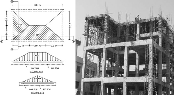
Disposition of slab load on supporting beams: Based on the placement of the beams (square or rectangular) triangular or trapezoidal shape distribution is performed. As for instance, for a rectangular slab of 6 m x 4 m the longer side beams distancing among A-B & D-C will bear the load of related trapezoidal portion while the shorter span beams distancing among A-D & B-C will support weight of roof slab arise out of the related triangular region.
Load on 6 m span = area of trapezoid x thickness of slab x density
Load on 6 m span = 8 x 0.15 x 25 = 30 Kn = 30 / member length = 30/6 = 5 Kn/m
The above estimated load of 30 Kn can be again transformed to UDL of 5 kn/m by dividing it with member length.
Load on 4 m span = area of triangle x thickness of slab x density
Load on 4 m span = 4 x 0.15 x 25 = 15 Kn = 15 / member length = 15/4 = 3.75 Kn/m
To get more details, go through the following article civilengineeronline99.blogspot.com
How to calculate the self weight of the different structural elements

~~~~~~~~~~~~~~~~~~~~~~~~
Published By
Rajib Dey
www.constructioncost.co
~~~~~~~~~~~~~~~~~~~~~~~~

Monday, October 22, 2018

Properties and benefits of rebar cages

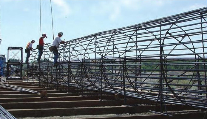
In drilled shaft construction, rebar cages are generally utilized to reinforce the shaft throughout excavation. To retain the strength of this cage as well as complete the entire construction project successfully, the design of the cage should be perfect.

Normally, a rebar cage for a drilled shaft comprises of longitudinal bars which are allocated with uniform spacing along the boundary of a cylinder.

In order to reinforce these bars, steel is arranged transverse to the bars and connected with ties, clamps or welds. Other elements of rebar cages may contain hoops for sizes, guides for centering the cages in the borehole and the premie inside of the cage, and stiffeners and pickup devices applied to facilitate lifting the cages.

Larger cages should contain temporary or permanent strengthening components to get rid of permanent distortion due to the stresses of lifting and placing.

As rebar cages are vital drilled shaft construction, it is essential that these cages should be properly constructed on the basis of a calculation of the stresses that it will endure.

The amount of reinforcing steel in a rebar cage should adhere to the structural requirements, taking into account combined stresses of axial load, lateral load and moment.

Properties of Steel Used for Rebar Cages

The American Society for Testing and Materials (ASTM) defines various steels which are employed for reinforcing drilling shafts.

The American Association of State Highway and Transportation Officials (AASHTO) approves most of these ASTM steels for being applied in building rebar cages for drilled shaft construction.

Normally, the steel accessible for these cages is AASHTO M 31 (ASTM A 615) in Grade 40 or Grade 60. If welding is required, then weldable steel, like ASTM A 706, should be utilized.

In case, there is risk for corrosion, galvanized or epoxy-coated steel are useful for longitudinal and transverse reinforcement. This is often stated for marine environments where the chloride content of ground or surface water is extreme.

As nicks and blemishes in the coating may happen at the time of the lifting and disposition of the rebar cases, rapid corrosion may occur. Under this situation, rebar without epoxy should be utilized and the drilled shaft should be filled with a low-permeability concrete to enhance the resistance strength against corrosion.

In unusual situations, high strength reinforcement is suitable. It may comprise of threaded couplers for splice connections and higher-strength rebar.

Contractors should compute the structural requirements of a drilled shaft cautiously while deciding the requirements of a rebar cage.

To get more details, go through the following articlewww.pilebuck.com

Properties and benefits of rebar cages

~~~~~~~~~~~~~~~~~~~~~~~~
Published By
Rajib Dey
www.constructioncost.co
~~~~~~~~~~~~~~~~~~~~~~~~

Wednesday, August 16, 2017

Various types of tests conducted to verify the quality of aggregates in road work

Aggregate is a vital element in pavement construction. The load transfer capacity of pavements is significantly impacted by the aggregated. So, it is recommended to examine the aggregates comprehensively prior to utilize them in the construction site.
The aggregates should contain the properties like durable and long-lasting with perfect shape and size so that the pavement can function monolithically. Aggregates are evaluated for strength, toughness, solidity, shape, and water absorption.
In order to decide the suitability of the aggregate for use in pavement construction, The following tests are conducted to check whether the aggregates are suitable to be utilized in pavement construction:

In order to decide the suitability of the aggregate for use in pavement construction, The following tests are conducted to check whether the aggregates are suitable to be utilized in pavement construction:
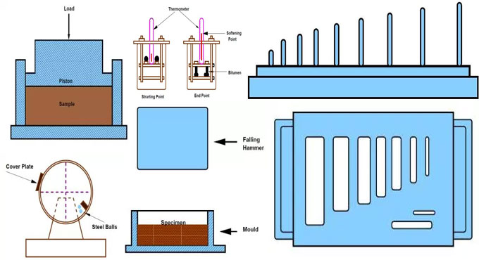
1.CRUSHING TEST: Crushing under compressive stress is a model to check the eligibility of pavement material for getting passed or failed. A test is organized with IS: 2386 part-IV and applied to find out the crushing strength of aggregates. The aggregate crushing value offers a relevant measure of resistance to crushing under increasingly employed crushing load.
2.ABRASION TEST: Abrasion test is accomplished to examine the rigidity of aggregates as well as determine whether they can be used for various pavement construction works. Los Angeles abrasion test is mostly suitable for executing the hardness property and it is implemented in India (IS: 2386 part-IV).
3.IMPACT TEST: The aggregate impact test is accomplished to verify the resistance to impact of aggregates. Aggregates which have passed 12.5 mm sieve and conserved on 10 mm sieve is filled with a cylindrical steel cup having internal dia 10.2 mm and depth 5 cm that is connected to a metal base of impact testing machine. The material is covered with 3 layers where each layer is tamped for 25 numbers of blows. Metal hammer having weight 13.5 to 14 Kg is set to drop with a free fall of 38.0 cm through vertical guides and the test specimen is dependent on 15 numbers of blows.
4.SOUNDNESS TEST: Soundness test is conducted to analyze the resistance of aggregates against weathering action, by carrying out accelerated weathering test cycles. The Porous aggregates is dependent on freezing and thawing is liable to decompose beforehand. To determine the stability of such aggregates, they are dependent on a faster soundness test as stated in IS: 2386 part-V.
5.SHAPE TESTS: The particle shape of the aggregate mass is set with the proportion of rough and enlarged particles in it. Large and enlarged aggregates may be damaged to higher workability and stability of mixes.
6.SPECIFIC GRAVITY AND WATER ABSORPTION: The design of concrete and bituminous mixes is mostly based on the properties like specific gravity and water absorption of aggregates. The specific gravity of a solid refers to the proportion of its mass to that of an equivalent volume of distilled water at an indicated temperature. As the aggregates may include water-permeable voids, so the following two measures of specific gravity of aggregates are utilized:
1. Apparent specific gravity and
2. Bulk specific gravity.
7.BITUMEN ADHESION TEST: Bitumen is compatible with all general types of road aggregates on condition that they are dry and do not contain dust. Without water, no adhesion issue of bituminous construction occurs.
If the aggregate is wet and cold, the adhesion issue may happen. This issue can be handled by eliminating moisture from the aggregate by drying and raising the mixing temperature. Besides, the existence of water leads to removal of binder from the coated aggregates. This problem happens if bitumen mixture is absorbent to water.
To get more information, click on the following link civilblog.org/
Various types of tests conducted to verify the quality of aggregates in road work

~~~~~~~~~~~~~~~~~~~~~~~~
PUBLISHED BY
RAJIB DEY
WWW.CONSTRUCTIONCOST.CO
~~~~~~~~~~~~~~~~~~~~~~~~

Friday, August 11, 2017

Brief explanation of rebaring method in reinforced concrete construction

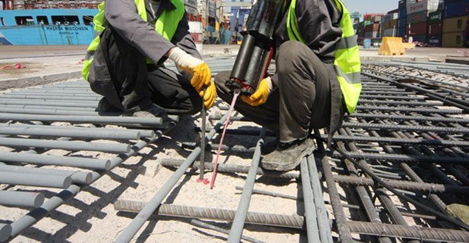
Rebaring technique in reinforced concrete construction stands for a process that is undertaken for fabricating and arranging of reinforcement bars perfectly based on the design and drawings intended for RCC works.
It is known fact that concrete is very durable in compression and weak in tension. The reinforcement bars alias rebars are strong in tension and these are combined with concrete to employ its tension property.
The responsible engineer produces the calculation of reinforcement bar for a reinforced concrete work. The engineer supplies us the particular details of the number of reinforcement bars as well as the shape and size of each bar for each work.

The responsible engineer produces the calculation of reinforcement bar for a reinforced concrete work. The engineer supplies us the particular details of the number of reinforcement bars as well as the shape and size of each bar for each work.
Various types of loads like tension, compression, lateral, horizontal and torsion are available which develop from pressure. To determine the strength of concrete, you have to find out whether concrete can withstand these loads or not.
The strength obtained by the R.C.C structure is based on the method and the techniques to be used for setting up the reinforcement bar. The reinforcement bars are primarily patterned over its surface to allow perfect bonding with the concrete.
Importance of Rebaring Technique in Reinforced Concrete Construction: The steel reinforcement usually is segregated into two categories i.e.
• Primary Reinforcement or Main Steel reinforcement
• Secondary reinforcement or distribution reinforcement
The objective of applying main steel reinforcement bars in R.C.C structures is to maintain resistance capacity for withstanding the entire design loads delivered to it. The secondary reinforcement bars are primarily used to maintain longevity and elegant look.
This reinforcement ensures to keep resistance for localized areas like limited cracking. These can also combat the stresses produced because of divergences in temperature.
The main bars which are used with indicated diameter, are bent at the ends. The stirrups belong to reinforcements which are arranged laterally, to place the main bars of the structural elements like beams and columns, in exact location.
The stirrups may come in various shapes like circular, square, rectangular, helical or diamond on the basis of the cross-section of the structural element. The reinforcement bars in the corners may appear as L – shaped.
The caging for the structural element to be decided should be perfectly fastened so as to keep the position of each bar unchanged throughout concreting. This is a check that should be always maintained throughout concreting otherwise it can hamper the stability of the structural member.
The rebars are primarily arranged at the junctions where the formwork of the structural element is closed and at the point where a new structural element should be fastened with the former one.


To gather more information, click on the following link theconstructor.org
Brief explanation of rebaring method in reinforced concrete construction

~~~~~~~~~~~~~~~~~~~~~~~~
Published By
Rajib Dey
www.constructioncost.co
~~~~~~~~~~~~~~~~~~~~~~~~

Saturday, August 5, 2017

Reinforcement details for slabs-on-ground with crack control factors

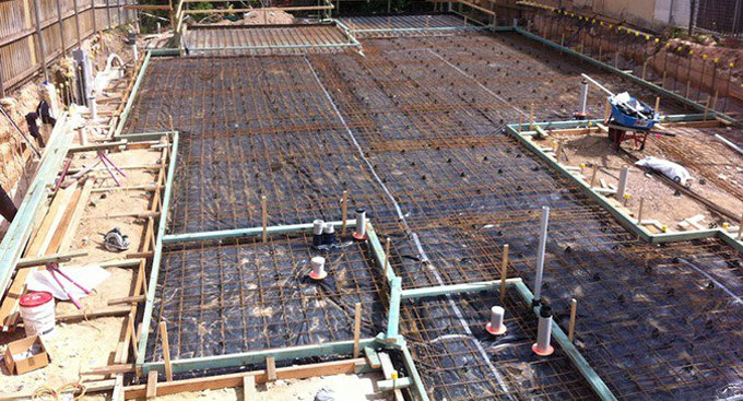
While designing the slabs, which are built up on ground, the crack control factors should be taken into account. Given below, reinforcement details for slabs-on-ground.
The density and the design of the slabs-on-ground are dependent on the cracks which are developed because of the external loading. The calculation for slab thickness is made on the basis of the suppositions of a slab being unreinforced and un-cracked.
For specific situations of slabs on ground, the steel reinforcement can offer a great solution. The characteristics of this method contains the following :-
1. The limiting of cracks occur because of shrinkage
2. Apply bigger joint spacing that is larger than the unreinforced slabs
3. The possibilities for cracks development may be avoided by provision for moment capacity and constancy for those areas.
4. Cracking can’t be resisted with the integration of reinforcement. These elements allow in minimizing or adjusting the produced crack width by genuinely raising the frequency of cracks that is created.
If a reinforcement design is proportioned and arranged perfectly, it can allow to restrain the width of the crack significantly and therefore the serviceability period of the slab is not impacted.
Thickness Design Methods for Slabs-on-Ground Construction
When reinforcement in the slab design is applied increasingly, the un-cracked strength of the slab is slightly affected. The various methods for thickness design like Pickett’s Analysis Method (PCA), WRI (Wire Reinforcement Institute) Design Method and COE methods can be employed for creating the design of slabs on ground with reinforcement.
Reinforcement for Slabs-on ground for Crack Width Control Only
The width of crack can be restrained by reinforcement on the basis of the two factors like the joint spacing and the thickness of the slab. Otherwise we can define the crack width control as a function of joint space and slab thickness.
There should be a minimum steel ratio of 0.5% of the slab cross section to facilitate the saw cut of contraction joints to be removed.
When the reinforcement is arranged, it is suggested to set the reinforcement bars nearer to the surface of the slab top surface devoid of compromising the minimum concrete coverage over the reinforcement.
Reinforcement details for slabs-on-ground with crack control factors

~~~~~~~~~~~~~~~~~~~~~~~~
Published By
Rajib Dey
www.constructioncost.co
~~~~~~~~~~~~~~~~~~~~~~~~

Saturday, July 29, 2017

Characteristics of Mass Concrete

Mass concrete is made with solid structures (> 80 cm). These structures frequently contain a greater volume. It signifies that large volumes of concrete should be set up in a short time. It needs highly well-organized planning and competent methods.

Mass concrete is applied for:

 Foundations for large loads
 Foundations for buoyancy control
 Solid walls (e.g. radiation protection)
 Infill concrete
The following major issues are formed with these enormous structures:
 Extreme internal and external temperature discrepancies throughout setting and hardening
 Excessive maximum temperatures
 High internal and external temperature deviations and as a result forced shrinkage
 Secondary consolidation (settling) of the concrete and as a result cracking occurs over the top reinforcement layers and also settlement under the reinforcement bars
Riska: All of these issues can lead to cracks and cement matrix defects assumed to be “skin or surface cracks” which may happen if the external/internal temperature variation is more than 15 °C or the outer layers can contract because of their initial drying out. Usually, the depth of skin cracks is few centimeters and can close again later.
Proper Measurement:
 Utilize cements with low heat development
 Low water content (curtailment in w/c ratio)
 Biggest possible maximum particle size (e.g. 0–50 rather than 0–32)
 If required, chill the aggregates to have a low initial fresh concrete temperature
 Set the concrete in layers (layer thickness < 80 cm)
 Restrain the bottom layers to make sure that the entire section is recompacted as soon as the top layer is set
 Start curing by applying thermal insulation methods
 Make sure the proper design and circulation of joints and concreting sections, so that heat can be dissipated and the temperature developments and deviations can be adjusted
Characteristics of Mass Concrete
~~~~~~~~~~~~~~~~~~~~~~~~
Published By
Rajib Dey
www.constructioncost.co
~~~~~~~~~~~~~~~~~~~~~~~~

Wednesday, July 12, 2017

Foundation3D – A powerful construction tool for footing analysis and design

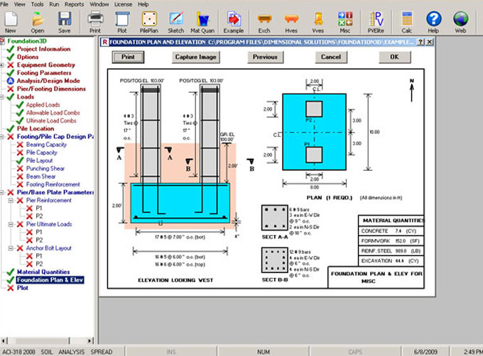
Foundation3D is a powerful tool that can be used for analyzing and designing spread and combined footing. The design of soil or pile supported foundation can be completed without any difficulty.
This tool is best suited for for creating the design of foundations for industrial equipment like horizontal exchangers and vessels, vertical vessels or towers, pipe racks and other plant supports.

By creating foundation design automatically, Foundation3D can constantly fulfill or outdo your project schedule requirements. Foundation3D facilitates to considerably enhance your productivity at each phase of your project ranging from equipment-specific automated load calculations to generating design sketches.
MAIN FEATURES:
• International Design Codes: Compatible with various international concrete design codes to finish the global projects successfully.
• User Defined Parameters: There are various customizable design options like concrete cover, pile arrangement and lots others to facilitate fulfilling different types of project specifications.
• Load Generation: Computes different types of equipment loads along with wind loads instantly and precisely to save significant times for load calculation.
• Load Cases and Combinations: Produces load cases and combinations for equipment foundation design which are mostly utilized and reduce major design time
• Soil/Pile Supported Designs: Accomplishes both soil and pile supported foundation designs in an collaborative surrounding facilitating you to explore with various “what-if” scenarios for getting best solution
• Analysis/Design Modes: Provides supports to both analysis and design modes for successful execution of your grass-roots or revamp projects, minimizing the total cost of ownership
• Numerous Foundation Components Design: Accomplishes the design process of several elements concerning a foundation like pedestals and footing, saving you the cost of learning multiple software solutions
• Rebar Layouts: Produces the layouts of rebar in pedestals and footings with customization options
• Material Quantities: Creates the material quantities to produce perfect cost estimates to your customers each time, at each stage of the project
• Detailed Design Sketches: Creates a detailed design sketch along with foundation plan, elevation, and sections, facilitating you to sum up the finalized design efficiently

• 2D Drawings: Collaborates with most recognized CAD engines to deliver 2D construction drawings, allowing you to control your design-drawing environment and human resources competently
• 3D Models: Collaborates with robust modeling tools to produce 3D models of the completed foundation design, facilitating you to fulfill or outdo compressed, variable project schedule requirements
• Multiple Reporting Options: Produces various types of customizable reports for your internal or client requirements
• Import Wizard: Imports support geometry and reactions from any superstructure software solution to execute foundation design instantly, enhancing your productivity.

Foundation3D – A powerful construction tool for footing analysis and design


~~~~~~~~~~~~~~~~~~~~~~~~
Published By
Rajib Dey
www.constructioncost.co
~~~~~~~~~~~~~~~~~~~~~~~~

Friday, June 30, 2017

How to design the reinforced concrete wall

You have to design the Reinforced concrete wall similar to a compression member. Reinforced concrete wall is suitable when there are no beams and load transmitted from the slab is massive or the density of the masonry wall is restrained.
RCC Wall is segregated as follow:
• Plain concrete wall, when rein. < 0.4%
• Reinforced concrete wall, when rein. > 0.4%

Load from slab is transmitted as axial load to wall. When depth is greater, it is known as RC wall. Design is identical to a RC column, breadth is similar to the density of wall and depth is equivalent to 1m. The design of RCC Wall is based on the following factors.
• Axially loaded wall
• Axially loaded with uniaxial bending
Categorization of concrete walls:
1. Plain concrete wall
2. Reinforced concrete wall
Under plain concrete wall, the reinforcement included is under 0.4% of c/s. In reinforced concrete wall, the proportion of employed steel is in excess of 0.4% and is designed in the same way as reinforced concrete columns. Slenderness ratio is equivalent to minimum of (l/t or h/t), where, l denotes effective length of wall, h stands for effective height of wall, t stands for thickness of wall. When < 12, the wall becomes short and if > 12, the wall becomes slender.
Braced and Unbraced Concrete Walls:
Braced: If cross walls are arranged for the walls so as to they can bear lateral load and 2.5% of vertical load, then the wall is defined as braced. If not, the wall is called as unbraced wall.
Note: Other walls under special cases are,
i) Cantilever wall
ii) Shear walls – To withstand lateral loads [Handle flexure created because of lateral loading on the structure, depth is allowed along the transverse direction]


To learn the detail process, watch the following link theconstructor.orgn

How to design the reinforced concrete wall


~~~~~~~~~~~~~~~~~~~~~~~~
Published By
Rajib Dey
www.constructioncost.co
~~~~~~~~~~~~~~~~~~~~~~~~

Saturday, June 17, 2017

ConSteel – A powerful structural Analysis software for steel & composite structures

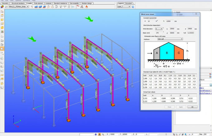
ConSteel Solutions has developed ConSteel with the support of some renowned structural scientists, engineers and programmers. It is a powerful software for analyzing any structure efficiently. It is primarily used for the construction of steel and composite structures.
It is suitable for all the stages of the design process ranging from modeling; integrated analysis and standard design; brief inspection of cross-sections and structural joints; flexible documentation. For the purpose of making analysis and design, ConSteel employs the latest techniques concerning the modern structural standards which deal with the 3D structural model as a whole throughout the entire process. The user-friendly interface among ConSteel and Tekla Structures, ConSteel and StruCad facilitates the user to export the full designed model together with the placed joints and considerably minimize the detailing costs.
The most updated version is ConSteel 11 that provides efficient analysis and design solution for structural engineers with significant enhancements for collaboration.
The restructured seismic analysis tool creates huge scopes for structural engineers to accomplish apparent and overall seismic calculation. The completely new csPI interface makes the structural modeling process more improved.

A 30-dasy free trial version is available for the users. Just click on the following link to download the trial version www.consteelsoftware.com

ConSteel – A powerful structural Analysis software for steel & composite structures


~~~~~~~~~~~~~~~~~~~~~~~~
Published By
Rajib Dey
www.constructioncost.co
~~~~~~~~~~~~~~~~~~~~~~~~

Wednesday, June 14, 2017

Different types of doors for building

The size of the door should be made with such dimension so that it becomes possible to move the largest object through the doors.
For residential buildings, the size of the door should start from 0.9 m × 2.0 m and over. Larger doors are built up at the core entrance to the building to make view elegant. Minimum sized doors are suitable for bath rooms and water closets. The proposed size is 0.75 m × 1.9 m. As a thumb rule height of door should have been 1 m over and above its width.
Types of Doors - Different types of doors are available which are categorized based on the disposition of shutters, construction processes, precepts of working operations and materials employed. Detailed information is given below for the doors which are frequently used in the buildings:
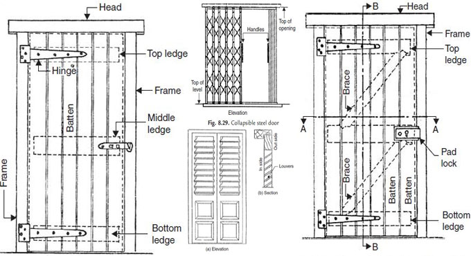
1. Battened and Ledged Doors: Battens are 100 mm to 150 mm large and made with 20 mm dense wooden boards. Their length is that of door opening. The battens are tied with horizontal planks, which are called as ledges of size 100 to 200 mm large and 30 mm thick. Generally, three ledges are employed one at top, one at bottom and the third one at mid-height. This is the easiest form of door and the economical also. Battens are fastened with tongued and grooved joint.
2. Battened, Ledged and Braced Doors: If doors are wide except for applying battens and ledges diagonal members, identified as braces, are used to make the door toughen.
Periodically, above two types of shutters are supplied inside wooden frame work and in those cases they are named as battened, ledges and framed doors.
3. Framed and Panelled Doors: This type of door comprises of vertical members, known as styles and horizontal members known as rails. The styles and rails are properly grooved to obtain panels. The panels may range from wood, A.C. sheet, glasses etc. The panels are flat or of raised type for having good appearance. These doors are used extensively. They are made of single shutter or of double shutter. If glass panels are employed they are known as glazed doors.
To get more information, go through the following link civilengineeringx.com
Different types of doors for building

~~~~~~~~~~~~~~~~~~~~~~~~
Published By
Rajib Dey
www.constructioncost.co
~~~~~~~~~~~~~~~~~~~~~~~
~

Wednesday, May 31, 2017

Download truss design spreadsheet

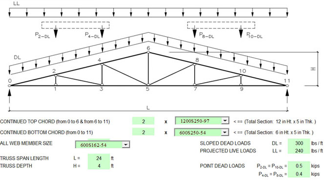
This estimating spreadsheet is specifically created for designing truss. By using this spreadsheet one can design light gage truss on the basis of AISI S100/SI-10 & ER-4943P.
The following design criterion is required for truss analysis.
The intermediate, finite element analysis contains shear deformations with E & G equivalent to 29500 ksi & 11300 ksi.
There are various rotations at similar joint of web to chord, since web pinned to continued chord.
Top chord shall be affixed to sheathing prior to inclusion of vertical load.
This spreadsheet will be useful for defining joint deflections with finite

To download the spreadsheet, click on the following link. www.finesoftware.eu

Download truss design spreadsheet

~~~~~~~~~~~~~~~~~~~~~~~~
Published By
Rajib Dey
www.constructioncost.co
~~~~~~~~~~~~~~~~~~~~~~~~

Wednesday, May 24, 2017

Overview of Peikko DSA Punching Reinforcement System for Cast-in-Place Concrete

This construction video tutorial provides the demonstration Peikko DSA Punching Reinforcement. It belongs to a Transverse Reinforcement System for Cast-in-Place Concrete. It is specifically designed to improve the strength of punching shear concerning elevated concrete slabs and slabs on grade devoid of raising their thickness.

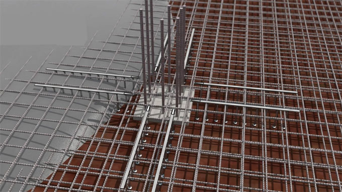
DSA rails consist of steel double-headed DSA Studs welded to a steel shape. The steel shape ensures the exact spacing and placing of the studs throughout their set up in concrete as per ASTM-A1044 standard. It should be used for both top and bottom installation.
Peikko DSA Punching Reinforcement offers an easy and consistent solution toward punching and shear failure which may happen in elevated concrete slabs, slabs on grade and footings.
If DSA Punching Reinforcement is applied in elevated slabs like reinforced concrete slabs or post-tensioned slabs, DSA Punching Reinforcement system disregards the requirement for column capitals. Therefore, forming and concrete costs are minimized significantly.
DSA reinforced cast-in-place elevated slabs are designed slimmer to minimize the entire construction height. It leads to huge savings in construction and running costs. The DSA system also provides a ceiling with uninterrupted clearance facilitating adaptability and simplicity of planning and installation of building services.
The fabrication process for DSA studs is done with low carbon steel grades C1010 through C1020. DSA Punching Reinforcement system adheres to the standard specification for steel stud assemblies for the shear reinforcement of concrete ASTM A-1044. It should be designed according to ACI 318-14 and CSA A23.3-14 which make it relevant in North America and Middle East.
Punching Reinforcement systems are also employed in foundations to curtail the thickness of footings, pile caps and slabs on grade. Other applications range from DSA rails are utilized as shear reinforcement in beams, walls and other concrete elements.


To get more information, click on the following link. www.peikkousa.com

Overview of Peikko DSA Punching Reinforcement System for Cast-in-Place Concrete

~~~~~~~~~~~~~~~~~~~~~~~~
Published By
Rajib Dey
www.constructioncost.co
~~~~~~~~~~~~~~~~~~~~~~~~

Friday, April 21, 2017

Fundamentals of Residential Construction 4th Edition – An exclusive ebook by Alexander C. Schreyer

Edward Allen, Rob Thallon and Alexander C. Schreyer have jointly published an exclusive construction e-book alias Fundamentals of Residential Construction. The book provides detailed guidelines on the each step of construction process for building up single family and multifamily home building. This book sheds light on each and every step associated with home construction which range from siting and foundations to finishing details. The book is enriched with more than 1,200 drawings and photographs whereas collaborative accompanying online resources facilitate in getting an overview of the material. This latest publication highlights the newest improvements in materials and methods, along with new coverage of sustainable building and energy efficiency, multifamily construction, prefabricated building components, and CAD/BIM planning tools in residential construction. Important exposure on wood light-frame construction, building systems, industrialized fabrication, insulating concrete forms, light-gauge steel and masonry construction, multi-family buildings, and more offers a solid understanding of residential construction methods, tools, and processes.
While constructing a home, sound knowledge is necessary for materials, structures, codes, and management processes as these can help in arranging the preparation of expertise essential for finishing a residential project successfully.
·         Be familiar with the pros and cons of common materials and systems
·         Gather knowledge on site preparation, foundations, and framing
·         Dip into the details of roofing, finishing, and energy efficiency
·         Recognize heating/cooling, plumbing, and electrical options
·         Explore through the newest codes, costs, and management best practices

Bar bending schedule offers the steel quantity requirement in a better way and thus delivers an option to make optimal use of the design in case of cost overflow.
The process becomes simple for site engineers to validate and approve the bar bending and cutting length throughout inspection prior to positioning of concrete with the support of bar bending schedule and thus facilitates in superior quality control.
It becomes easier to handle the reinforcement stock necessary for identified time duration.
It will facilitate to fabrication of R/F with structure.

Buy the book online from Amazon by clicking on the following link 
Buy Now


~~~~~~~~~~~~~~~~~~~~~~~~
Published By
Rajib Dey
www.constructioncost.co
~~~~~~~~~~~~~~~~~~~~~~~~
Fundamentals of Residential Construction