adsense analytic

Showing posts with label Structural Calculations. Show all posts

Thursday, December 13, 2018

How to calculate the self weight of the different structural elements

A building load belongs to a force that should be confronted by the house frame. The frame should be designed in an efficient manner to resist eight of these loads ranging from wind, earth, and snow devoid of catastrophic stress on the structure.

Given below, the detail calculation method of self weight for the structural components:

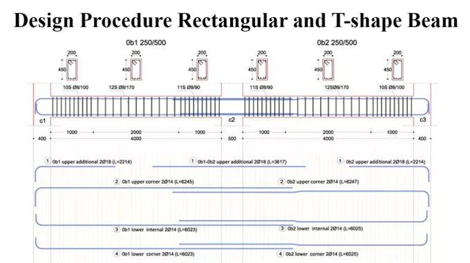
a. Beam: It is applicable to different types of shapes like rectangular/square/tee/trapezoid for measuring the weight.
Weight of member = cross section area of member x length of member x RCC density
Suppose, the width is taken as 0.3 m and depth is taken as 0.45 m for the beam section with 5 m clear length & material density = 25 kn/m3 (for RCC), the weight should be as follow :-
Weight of beam = (0.3 x 0.45) x 5 x 25 = 16.875 Kn
The above calculated weight of 16.875 Kn stands for the total weight that should be transformed into Uniformly Distributed Load (UDL) by dividing the total weight with member length.
UDL = 16.875/5 = 3.375 Kn/m


b. Column: While measuring the self-weight of a column, the terminology of member length should be converted to member height & the weight of column should be computed as point load only its conversion in UDL is not necessary.

c. Slab: For RCC slabs, the weight of roof slabs is employed as invariable pressure in Kn/m2. For making analysis, a 1 m x 1 m square section is taken into consideration & the volume of the RCC is measured & then the same is multiplied with the density for derivation of pressure in kn/m2.

Weight of slab = (1 x 1 x slab thickness) x RCC density

In the above formula as (1 x 1) doesn’t impact the estimate thus it can be further clarified as follow :-
Weight of slab = slab thickness x RCC density


If the thickness of the slab is 0.15 m, then the estimate is done as follows :-
Weight of slab = 0.15 x 25 = 3.75 Kn/m2


In the above estimate of RCC slab weight further supplementary load resulting from floor finishes should be generally taken into consideration for stone/cement floorings as 0.75 kn/m2 to 1.5 kn/m2.
The U-value unit is the inverse those of R-value:
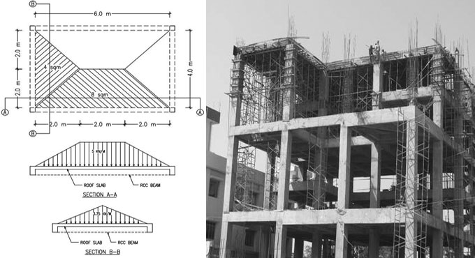
Disposition of slab load on supporting beams: Based on the placement of the beams (square or rectangular) triangular or trapezoidal shape distribution is performed. As for instance, for a rectangular slab of 6 m x 4 m the longer side beams distancing among A-B & D-C will bear the load of related trapezoidal portion while the shorter span beams distancing among A-D & B-C will support weight of roof slab arise out of the related triangular region.
Load on 6 m span = area of trapezoid x thickness of slab x density
Load on 6 m span = 8 x 0.15 x 25 = 30 Kn = 30 / member length = 30/6 = 5 Kn/m
The above estimated load of 30 Kn can be again transformed to UDL of 5 kn/m by dividing it with member length.
Load on 4 m span = area of triangle x thickness of slab x density
Load on 4 m span = 4 x 0.15 x 25 = 15 Kn = 15 / member length = 15/4 = 3.75 Kn/m
To get more details, go through the following article civilengineeronline99.blogspot.com
How to calculate the self weight of the different structural elements

~~~~~~~~~~~~~~~~~~~~~~~~
Published By
Rajib Dey
www.constructioncost.co
~~~~~~~~~~~~~~~~~~~~~~~~

Tuesday, December 11, 2018

How to design rectangular and T shape beam

Beams are defined as members which are exposed to flexure. So, it is important to give attention to the analysis of bending moment, shear and deflection.

When the bending moment operates on the beam, bending strain is created. The resisting moment is formed with internal stresses. Under positive moment, compressive strains are developed in the top of the beam and tensile strains in the bottom.

Concrete is weak against tensile strength and it is not perfect for flexure member by itself. The tension side of the beam will collapse prior to failure of compression side when beam is exposed to a bending moment devoid of the reinforcement. To resolve this issue, steel reinforcement is provided on the tension side. The steel reinforcement withstands all tensile bending stress as tensile strength of concrete is zero when cracks are formed.

Rectangular beam

Accept the depth of beam with the ACI code reference, least thickness until the deflection is considered.
Accept the beam width (ratio of width and depth is approx 1:2).


Calculate self-weight of beam & design load.
Work out factored load (1.4 DL + 1.7 LL).
Calculate design moment (Mu)
Work out maximum possible nominal moment for singly reinforced beam (φM n ).


Determine reinforcement type by making comparison between the design moment (M u ) and the maximum possible moment for the singly reinforced beam (φM n ). If φM n remains under Mu, the beam should be designed as a doubly reinforced beam otherwise the beam should be designed with tension steel only.

Find out the moment strength of the singly reinforced section (concrete-steel couple).

Calculate the necessary steel area for the singly reinforced section.
Determine an essential residual moment, deducting the total design moment and the moment capacity of the singly reinforced section.
Calculate the extra steel area from the required residual moment.
Calculate the total tension and compressive steel area.
Design the reinforcement with the selection of the steel.
Verify the actual beam depth and assumed beam depth.


T-shape Beam

Calculate the design moment (Mu ).
Presume the effective depth.
Choose the effective flange width (b) depending on ACI criteria.


Workout the practical moment strength (φM n ) anticipating the total effective flange is supporting the compression.

When the practical moment strength (φM n ) is greater than the design moment (Mu ), the beam is measured as a rectangular T-beam with the effective flange width b. If the practical moment strength (φM n ) is not more than the design moment (Mu ), the beam will operate as a true T-shape beam.

Determine the approximate lever arm distance for the internal couple.
Work out the approximate required steel area.


Design the reinforcement
Verify the beam width
Calculate the actual effective depth and analyze the beam


How to design rectangular and T shape beam

Read Continue


~~~~~~~~~~~~~~~~~~~~~~~~
Published By
Rajib Dey
www.constructioncost.co
~~~~~~~~~~~~~~~~~~~~~~~~

Thursday, August 30, 2018

EdiLus-RC – A powerful software for concrete design & reinforced concrete structural calculation

EdiLus-RC is an exclusive software for making perfect concrete design that deals with structural calculations toward new and subsisting buildings in reinforced concrete by means of the most simple and effective SMART BIM object input.

The first structural calculations BIM software for reinforced concrete buildings.

To use the software, just draw the structural members to input nodes, loads, constraints… the computational model is fully ascertained from the drawing automatically.

With this software, it is possible to design and measure new buildings as well as accomplish checks and structural redevelopments of subsisting reinforced concrete buildings with cladding work, platings, FRP interventions, etc. Particular functions will help in obtaining information concerning the subsisting structure, the material strengths defining its reinforcements.

It is also possible to insert new roof structures to the subsisting building, elevations, or even extra floors, etc., and then move on to an overall validation.

Finite Element Method solver integrated in the software: A FEM solver is added with the software to provide a unitary experience in structural design. Graphical input, the static and dynamic calculations, structural analysis, modifications and construction documents (charts, tables and reports) are all created with the very same software in a simple and incorporated manner.

Graphical analysis of the calculation results: Each object is illustrated with its stress and deformation values once the calculation process is completed. Besides, the detailed calculation leads to numerical form, EdiLus also offers different graphical views that facilitate you to realize how the structure functions at a glance. The process for improvidngh the static or dynamic behaviour of the structure is simple and intuitive.

Object oriented modelling, 3D input based on Magnetic Grids: Design with intelligent objects that comprises of information concerning their characteristics of resistance and spatial location.

The complicated spatial structures can now be easily modeled with Magnetic Grids, the robust tool that facilitates you to develop a network of magnetic points in space where the different structural components are automatically attached.

Automatic reinforcement schedules design: EdiLus can design the reinforcement schedules for all structural members efficiently. A trouble-free and robust editor that facilitates you to freely adjust the reinforcement bars even after the calculation with an immediate re-verification of the structural element.

Structural checks and Technical Reports: EdiLus-RC examines structural elements sections as per the EUROCODES technical provisions and regulations. Structural engineers can easily select the national annex and the response spectrum concerning the country in which the calculations should be done.

Cost Estimating integrated with structural design: The modelled structure creates a dynamic Bill of Quantities automatically, in reality, the complete project, and any consequent variations, are instantly updated in the project’s cost estimate.

Incorporation with the Edificius BIM model: With integration of EdiLus in Edificius, Architecture and Structural engineering issues can be easily interacted facilitating the structural engineer to design and compute all the structural elements precisely.

To download a free trial version, click on the following link www.accasoftware.com

EdiLus-RC – A powerful software for concrete design & reinforced concrete structural calculation

~~~~~~~~~~~~~~~~~~~~~~~~
Published By
Rajib Dey
www.constructioncost.co
~~~~~~~~~~~~~~~~~~~~~~~~

Wednesday, January 24, 2018

Prestressed Girder SUPERstructure design and analysis

It is powerful open source software that is used for designing and analyzing of precast-stress free girder bridges and can handle easily. It allows creating models in a simple way and continuously stretches structures and designs as per with the AASHTO LRFD Bridge Design Specifications.

It also has advanced Bridge Information Modeling or BrIM capabilities that help users to keep focused continuously on modeling, designing and analyzing real bridges.

PGSuper examines and designs formed girders for every critical stage such as: casting, lifting, carrying, building, service and final conditions. The automatic designer fixes the prestressing, solid strength, lifting, transportation and slab side requirements and this software has the broadest and detailed reports and every detailed calculation can be reviewed.
PGSuper 2.8.2 is created by the Washington State Department of Transportation’s Bridge and Structures Office and licensed under the Alternate Route Open Source License. The software file size is about 24.09 MB and works with the Windows only and is free to be used and can be modified by all; but it is not the most capable precast girder bridge design program. This software is mainly designed by Bridge Engineers to use n high-production design environments and supports a huge order of parametric shapes and has user defined filament, reinforment and stirrup layouts.
Here are some design specifications of PGSuper, such as:
• Has AASHTO LRFD 1998-2008
• It rectify all suitable specifications
• It is very much configurable
• Comes with User Input Stress Limits
• Can computed and has User-Input Distribution Factors
• Also has User-Input LRFD Load Modifiers
• Have five methods of Loss Calculations.
There is some other software that has the same features like PGSuper and here are some descriptions about them:
1. PGSPLIC 1.0: It is joined girder analysis software of Washington State Department of Transportation and has been developed for the Alternate Route Project.
2. BRIDGELINK 3.0: BridgeLink is an integrated bridge engineering software tool for analysis, design and load rating.
3. RSPBR2 1.3: It is a plane frame structural analysis program for supporting bridge engineers in design and checking beam bridges.
4. QCONBRIDGE 4.3.2: it is a live road analysis program to continuous bridge frames.
5. BARLIST: This program is used for calculating the weight of steel reinforcement bars which is used in a bridge structure and for assisting in the creation of barlist drawings for bridge project contract plans.
6. PSGSIMPLE: it is a spreadsheet that performs prior analysis of a precast prestressed bridge girder at the prestress transfer and service stages.
To gather more information, go through the following construction article pgsuper.com
Prestressed Girder SUPERstructure design and analysis

~~~~~~~~~~~~~~~~~~~~~~~~
Published By
Rajib Dey
www.constructioncost.co
~~~~~~~~~~~~~~~~~~~~~~~~