adsense analytic

Thursday, March 29, 2018

Detail lists of useful construction tools

Given below, the detailed lists of various useful construction tools and their applications :-

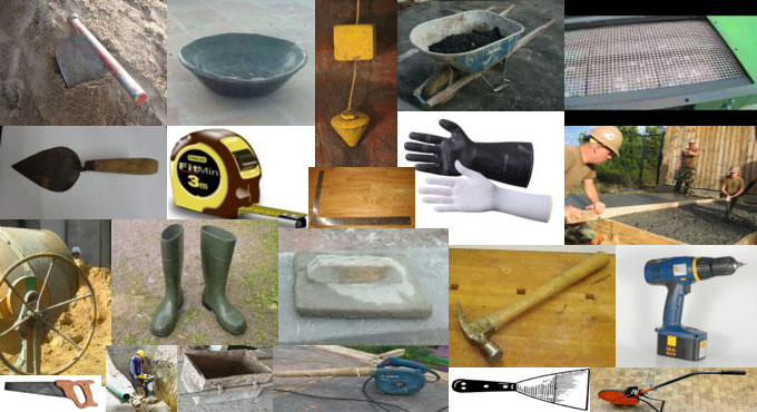
Hoe – It is effective for digging and arranging concrete, cement mortar in head pan. Hoe is also useful for excavating the soil but here the metal plate is set with acute angle to the wooden handle.

Head Pan – It is utilized to transmit materials. Head pan is built with iron to uprise the excavated soil or cement or concrete to the construction site etc. it is mostly found in construction sites.

Masonry trowel – The objective of this tool is to organize cement mortar. It refers to a hand trowel that is applied in brickwork or stonework for the purpose of leveling, dispersion and shaping mortar or concrete.

Measurement Tape – It is employed to examine the thickness, length, widths of masonry walls, foundation beds, excavated trenches etc.

Plumb Bob - It is applicable for verifying the vertical alignment of the structures. It comprises of a solid metal bob attached with the end of a thread. It can also be applied in surveying to level the instrument position.

Wheel Barrow – It is useful for carrying out cement mortar or any materials. Often, it is utilized to estimate the quantities of materials for site level concrete mixing.

Concrete Mixer – It is a machine that is used for blending the concrete perfectly with water, fine aggregate, coarse aggregate and cement at construction site.

Vibrator - It is utilized to vibrate the concrete when pouring is started. For the purpose of workability, water is added to concrete. To get rid of that, vibrators are applied.

Bump Cutter/Screed – The objective of this tool is to level fresh concrete surface particularly in slab concrete.

Wooden Float/wooden rendering float - This tool is useful for providing a flat finish to the plastered area.

Crow Bar - This tool is found in formwork to eliminate nails from boards. Crow bar is also applied for digging the ground and taking out the roots of trees in the ground, nails etc.

Framing Square - This tool is mostly found in Brickwork, Plastering to verify exact angle.

Line Level - This tool is required to verify horizontal level in brickwork, plastering , flooring and tile works.

Flat Pry Bar - This tool is found in shuttering and often utilized to modify the column formwork to align.

Digging bar - This tool is used to divide and unloose the compacted / hard surface area. Digging bar refers to a solid metal rod having pin shape at the bottom. It is also utilized to dig the hard surfaces of ground.

For more information, go through the following link www.civilology.com

Detail lists of useful construction tools

~~~~~~~~~~~~~~~~~~~~~~~~
Published By
Rajib Dey
www.constructioncost.co
~~~~~~~~~~~~~~~~~~~~~~~~

Wednesday, March 28, 2018

Specific Gravity & Water Absorption of Coarse Aggregate

This construction video tutorial is useful for concrete mix design. This video tutorial is based on specific gravity and water absorption of course aggregate.

Different types of apparatus like weighing balance, thermostatically controlled oven, glass vessel, enamel tray, air tight container, 10 mm IS sieve, sample are required for this purpose.

The following methods are used :-

Sieve the sample with the help of 10 mm sieve to eliminate thinner particles and then select 1 kg sample. Set the sample in a glass vessel and load the vessel partially with water.

Retain the sample for 24 hours in order that these are fully soaked.

After completion of 24 hours, load the vessel entirely and cover the vessel by disc to resist entrapping of air into vessel. Dehydrate the vessel from outside. Now measure the weight.

Weight of vessel with disc + water + sample (A) = 3372 gms.

Discharge the water of vessel. Now aggregates are set on a dry cloth unless it comes in SSD (surface saturated dry) condition. Now take the weight as C = 990 gms.

Now load the vessel fully with water. Cover the vessel with disc so that no air can enter into it. Now, again take the weight.

Weight of vessel together with disc and water (B) = 2574 gms.

Now, put the SSD sample in a tray made of enamel and retain it in oven at 1000C for 24 hours. Once 24 hours are completed, let the sample cool in air tight container.

Now, take the weight of the oven dry sample as D = 982 gms.

The following formula is used to determine the specific gravity :-

D/C-(A-B), here, A denotes weight of vessel with disc + water + sample = 3372 gms
B denotes weight of vessel with disc + water = 2754 gms


C denotes weight of SSD sample = 990 gms
D denotes weight of oven dry sample = 982 gms


To determine water absorption, use the following formula :-
C-D/D x 100 = 990 – 982/982 x 100 = 0.81%


To get more detail information, go through the following video tutorial.

Specific Gravity & Water Absorption of Coarse Aggregate

Read more

~~~~~~~~~~~~~~~~~~~~~~~~
Published By
Rajib Dey
www.constructioncost.co
~~~~~~~~~~~~~~~~~~~~~~~~

Tuesday, March 27, 2018

Some useful notes on steel structure

Sami Ullah, the eminent engineer, presents another useful video tutorial for civil engineering students. This video provides detail information on steel structures.

Standard bar splices (lapping length for the steel) for tension member applicable to all members :-


For nos #3, 4 and 5 bars splice length is = 12 inches
For no #6 bar splice length = 22 inches
For no #8 splice length = 40 inches
General notes:
All the positive (bottom) reinforcement is demonstrated as solid lines in the drawing.
All the negative (top) reinforcement as a dashed alias broken line in the drawing.
Clear cover for slab = 0.75 inches
Clear cover for beam = 1.5 inches
Clear cover for column = 1.5 inches
Clear cover for foundation = 2.5 inches
The applied concrete should contain a minimum 28 day’s cylinder crushing strength of 3000 psi.
Splice length of steel for M20 concrete :-
Slab = 60d
Column = 45d
Beam = 60d
Here, d denotes dia of steel that is utilized in a slab.
To get more details, watch the following video tutorial.
Video SourceSami Ullah

~~~~~~~~~~~~~~~~~~~~~~~~
Published By
Rajib Dey
www.constructioncost.co
~~~~~~~~~~~~~~~~~~~~~~~~

Monday, March 26, 2018

Some useful tips to work out the quantities of tiles for setting up tiles floor

If it is required to plan or set up your individual tile floor or just estimate the materials for budget purpose, you have to find out the quantities of tiles as per your need.

By using a measuring tape and some simple math, it is possible to calculate the quantities of tiles as well as total cost of the project.

For this purpose, you require the followings :-

• Paper
• Pen or pencil
• Measuring tape
• Calculator (optional)
The steps should be undertaken to determine the tiles quantities.

• Step 1

• Work out the length of one side of the room. For any wall project, calculate the length of the wall directing up and down.

• Step 2

• Work out the length of the other side of the room. For any wall project, calculate the length of the wall directing from left to right.

• Step 3

• Multiply the two measurements. Multiplying the length with the width will determine the square footage of the project area. As for instance, if the length of the room is 12 feet and width is 10 feet, then multiply 12 x 10. The square footage of this room will become 120 square feet.

• Step 4

• Translate the square footage to the amount of tile you need. Tile is generally found in boxes, and it is necessary to purchase the whole box. Divide the total square footage of the room with the total square footage of the tile in the box. Suppose, each box comprises of 10 square feet of tile. Therefore, for 120 square footage area, 10 will be 12 times in 120 and it is essential to purchase minimum 12 boxes.

• Step 5

• Calculate the average for your requirements. You should never purchase just the amount of tile you require, as you should require a little extra for cuts, waste, breaks, and mistakes. Multiply the square footage of the room by 10%, then include this amount to the total square of the room. This is the total amount of square footage that should have been purchase. As for example, 10 x 120 = 12, and 120 + 12 = 122. So, 122 square feet of tile will be required.

When the style or color is suspended and it is required to substitute a broken tile or two, you will require extras on hand for repairing purpose. For this purpose, you have to purchase extras. If extras are not purchased, then the entire floor should have been substituted.

 Some useful tips to work out the quantities of tiles for setting up tiles floor

Read more
~~~~~~~~~~~~~~~~~~~~~~~~
Published By
Rajib Dey
www.constructioncost.co
~~~~~~~~~~~~~~~~~~~~~~~~

Friday, March 23, 2018

Different types of abutment and their properties

Abutment stands for a structure. The ends of a bridge is supported with it.

Retaining Wall is considered as the most recognized abutment structure. Even though other types of Abutments can also be set up and used. The purpose of a retaining is to retain an earth embankment or water.

Abutment offers the following functionalities

Transmits the loads from Bridge Ends to the ground.

Resists any loads which are enforced on it directly.

Offers entry to the vehicular and pedestrian into the bridge.

For Retaining wall, bearing strength of abutment and sliding endurance of the foundation materials and overturning strength should be examined properly.

Types of Abutments: According to standard specifications, the abutments are categorized as follow :-

Stub abutments, Partial-depth abutments, Full-depth abutments, Integral abutments, Partial-Depth Abutment

How to choose perfect abutments: On the basis of the following factors, the most perfect abutments can be chosen :-

a. Construction and maintenance cost
b. Cut or fill earthwork situation
c. Traffic maintenance throughout construction
d. Construction period
e. Protection of construction workers
f. Accessibility and cost of backfill material
g. Superstructure depth
h. Size of abutment
i. Horizontal and vertical alignment alterations
j. Area of excavation
k. Attractiveness and conformity with adjoining structures
l. Prior knowledge with the type of abutment
m. Ease of use for assessment and maintenance.
n. Predicted life, loading condition, and acceptability of deformations.

Forces operative on Abutments: Earth pressures applied on an abutment are categorized with regards to the direction and the magnitude of the abutment movement.

1. At-rest Earth Pressure: It the wall is set firmly and becomes stagnant, the pressure applied by the soil on the wall is known as at-rest earth pressure.
2. Active Earth Pressure: When a wall is shifted from the backfill, the earth pressure is reduced. (active pressure).
3. Passive Earth Pressure: If it is shifted toward the backfill, the earth pressure is raised (passive pressure).
Different types of abutment and their properties

~~~~~~~~~~~~~~~~~~~~~~~~
Published By
Rajib Dey
www.constructioncost.co
~~~~~~~~~~~~~~~~~~~~~~~~

Thursday, March 22, 2018

How to work the volume of concrete in a retaining wall

This construction video will provide some useful tips on computing the volume of concrete for retaining wall.

Retaining wall is defined as a rigid wall that is designed and constructed to withstand lateral pressure of liquid, earth filling, sand or other coarse materials which it is holding back.

Suppose, a retaining wall is segregated into two sections, section A is taken as base slab and section B is taken as the stem of retaining wall.

Therefore, the volume of retaining wall is determined with the following formula :-

Volume of retaining wall = Volume of base slab + Volume of Stem

Volume of base slab = length x breadth x height

= 10 x 3 x 0.2 (after converting 200 mm to meter) = 6m3

As the stem is a trapezoid, the following formula is used to calculate it’s volume :-

Volume of stem = [{a+b)/2} x h] x l

After putting the values, we get :-

= [{(0.5 + 0.2)/2} x 3] x 10 = 21m3

Therefore, total volume of retaining wall = 6 + 21 = 27m3

Therefore, the volume of concrete for the retaining wall = 27m3

If the retaining wall is segregated into three parts like part A, part B and part C. Part A is taken as the base slab, part B is taken as the stem and part C is taken as the counterfort of the retaining wall.

Therefore, the volume of retaining wall = Volume of base slab + volume of stem + volume of counterfort

= Volume of A + Volume of B + Volume of C

To learn the remaining calculation process, go through the following video tutorial.
Video Source: Nice engineering


~~~~~~~~~~~~~~~~~~~~~~~~
Published By
Rajib Dey
www.constructioncost.co
~~~~~~~~~~~~~~~~~~~~~~~~

Wednesday, March 21, 2018

Brief overview of metal casting

Casting means development of hot liquid metals or several metals which are cooled after obtaining the constituents like clay, plaster and concrete mixed in. This method is also utilized in forming cars or planes.

Various types of castings are found in construction industries. Given below, the detail lists of them :-

Non-expendable mold casting - This type of casting is categorized as continuous, centrifugal, die, and permanent casting.

Continuous casting - It is utilized as a superior procedure of casting for high-volume, continuous production of metal sections with constant cross-section. Here, the liquefied metal is poured into a water-cooled and open-ended copper mold. It offers a layer of solid metal to be developed over the still-liquid centre.

Continuous casting is very economical and hence it is mostly recognized among construction professionals. The metals incessantly casted are aluminum, copper, and steel.

Centrifugal casting - This option is not influenced by both-pressure and gravity since its own force feed is constructed by means of utilizing a temporary sand mold in a spinning chamber. The completion time fluctuates with regards to the application itself. True-and-semi-centrifugal processing facilitates 30 to 50 pieces to be finished every hour.

Die-casting – It is most crucial of all the methods, Under this method, the melted metal is forced into cavities of mold in high pressure. These castings include non-ferrous metals, especially-alloys of aluminum, copper, and zinc.

Sand casting – It is considered as the most convenient and most recognized casting types. It entails very small size operations. Here, the bonding of sand occurs with the use of clays. The process can be initiated prior to recycling.

Plaster casting - It is also applied extensively and is closely equivalent as sand casting, excluding plaster.

If it is required to construct your own metal works, just consult with a brand or professional relating to equipment and safety tips.

Source: civilengineersite.com

Brief overview of metal casting

~~~~~~~~~~~~~~~~~~~~~~~~
Published By
Rajib Dey
www.constructioncost.co
~~~~~~~~~~~~~~~~~~~~~~~~

Tuesday, March 20, 2018

How to perform slump cone test for testing the workability of concrete

This construction video tutorial is based on slump cone test. It is one of the most recognized field tests on fresh concrete.

Slump test is undertaken to evaluate the functionality of fresh concrete as well as verify the water ratio and the consistency of concrete from batch to batch.

The instruments which are used in slump test comprise of a mould shaped like the frustum of a cone having the following dimensions :-

Bottom Diameter : 200 mm
Top Diameter : 100 mm
Height : 300 mm
Tamping rod of steel should contain diameter of 16 mm, 600 mm long and rounded at one end.


The following methods are used to work out slump :-

nternally and externally cleanse the inner surface of mould without applying any grease or oil.

Fill the mould with concrete in 4 layers.

Tamp each later with 25 strokes of the rod to get rid of bubbles and voids.

Allocate the strokes consistently over the whole cross-section of the mould.

The rod should infiltrate each bottom-line layer.

By applying a trowel, eliminate surplus concrete after the top layer.

Take away mould gradually and vertically.

The concrete will slump or slide.

Calculate the slump height in mm.

To maintain normal functionality, the slump should not be over 50 mm.

Cleanse the slump cone.

To get more detailed information, go through the following video tutorial.


~~~~~~~~~~~~~~~~~~~~~~~~
Published By
Rajib Dey
www.constructioncost.co
~~~~~~~~~~~~~~~~~~~~~

Monday, March 19, 2018

Civil Engineering: Conventional and Objective Type (2018-19 Session) – An exclusive e-book for civil engineering students

Civil Engineering: Conventional and Objective Type (2018-19 Session) is an exclusive e-book written by R.S.Khurmi and J.K. Gupta. The book is available in paperback format.

The book comprises of 724 pages as well as near about 4800 topic-wise solved and unsolved questions.

The book is considered as a very good resource for undergraduate students of Civil Engineering as they can use the book as reference guide for preparing them for different types of competitive examinations like GATE, UPSC, IAS and IES as well as university examinations.

The book covers the following topics :-
• Oscillations and Waves
• Electrostatics
• Magnetostatics and Electrodynamics
• Electromagnetic Waves
• Light
• Interference
• Diffraction
• Polarization
• Optical activity
• Optical fibres
• Architectural Acoustics
• Ultrasonics
• Electron Emission
• Electron Ballistics
• Electron Optics
• Elements of Thermodynamics
• Thermoelectricity
• Special Theory of Relativity
• Atomic Physics
• Quantum Mechanics
• Atomic Nucleus and Nuclear Energy
• Cosmic Rays and Elementary Particles
• Nuclear Instruments
• Lasers
• Holography
• Crystal Structures
• Crystal Defects
• Conductors
• Band Theory of Solids
• Semiconductors
• Semiconductor Diodes
• Bipolar Junction Transistor
• Dielectrics
• Magnetic Materials
• Superconductivity
• Modern Engineering Materials
• Non Destructive Testing
• Vacuum Technology
• Nanotechnology
• Geometrical Optics
One can purchase the book online from amazon by clicking on the following link www.amazon.in
Civil Engineering: Conventional and Objective Type (2018-19 Session) – An exclusive e-book for civil engineering students

~~~~~~~~~~~~~~~~~~~~~~~~
Published By
Rajib Dey
www.constructioncost.co
~~~~~~~~~~~~~~~~~~~~~~~~

Saturday, March 17, 2018

Some vital points required for construction bid formation

CAREFUL STUDY OF THE CONTRACT DOCUMENTS: The contract documents which are provided to the contractor or delivered for his inspection comprise of general contract conditions, drawings, specifications, bills of quantities etc.
These documents should have been examined cautiously to ensure whether there are any unusual conditions, specifications as well as any feature of the work which should be taken into consideration throughout pricing.
Sub-contractor’s work: Make relevant quarries about prices with sub-contractors and material suppliers for their relative segments of the job.
Site visit: It is vital to determine the conditions under which the work should have been accomplished and their effect on pricing.
a. Complexity to get entry to the site
b. Restricted space on the site for vehicle movements
c. Type of soil and density of water table
d. Accommodation for space for preserving materials on site
e. Accessibility of materials, their sources and existing market prices
f. Local resources of skilled and unskilled labor, current wages for workmen
g. Source and cost of water required for construction
h. Power and lighting source, and the cost of arranging, preserving and serving power connection to the site.
TIME FOR COMPLETION: The bidder then works out the time period for executing the work and the number and category of permanent staff suitable for the nature of the work for construction management. It facilitates to compute the establishment charges.
TEMPORARY WORKS: The value of any temporary works required to set up the construction and to dispose of on finishing like temporary office necessary for construction management purpose, lay up sheds for building materials, access road, water supply, depreciation of construction equipments, insurances, taxes, etc.
Article Sourcecivilengineersite.com

Some vital points required for construction bid formation
~~~~~~~~~~~~~~~~~~~~~~~~
Published By
Rajib Dey
www.constructioncost.co
~~~~~~~~~~~~~~~~~~~~~~~~

Friday, March 16, 2018

How to calculate hinged support, normal thrust and shear of a three hinged circular arch

This construction video tutorial is based structural analysis. You will learn how to make calculation of reaction at the support as well as normal thrust and shear for three hinged circular arch.


This video is presented by renowned engineer Mr. Parag Pal.
Three hinged system:
a. A three hinged system comprises of two plates, attached collectively with a hinge containing two hinged supports A and B resting on the ground.
b. When the plates 1 and 2 comprises of curved bars, the system is known as a three-hinged arch.
c. The distance 1 among the centers of the hinges at the support is known as the span of arch.
d. When distance f from the center of the crown hinge to the straight line going through the former two is defined as its rise.
The reactions of a three hinged arch will be completely established with four parameters, as for example, the amounts of reaction Ha, Hb, Va, and Vb.
So, a three hinged system is always statically determinate.
Benefits:
a. The bending moments and shears operative over cross sections of three hinged arches are significantly smaller as compared to the subsequent stresses in a simple beam covering the equivalent span and bearing the same load. So, three hinged arches are inexpensive relating to ordinary beams, specifically for large span structures.
b. Calculations are very simple as compared to other type of arches.
c. No bending moments are generated at the abutments and the crown since hinges cannot withstand moments.
d. Differential settlements of the supports do not impact stresses, since the pines or hinges allow the arch to assume the slightly different shape consequent upon settlement.
e. The pin joints allow the arch to modify itself to expansions and contractions because of alterations in temperature.
In this video, solution is given to the following problem: A three-hinged circular arch hinged at the springing and crown points contain a span of 40 m and a central rise of 8 m. It bears a consistently distributed load 20 kN/m over the left-half of the span collectively along with a concentrated load of 100 kN at the right quarter span point.
Determine the supports, normal thrust and shear at a section 10 m from left support.
To get the solution, go through the following video tutorial.

Read more

~~~~~~~~~~~~~~~~~~~~~~~~
Published By
Rajib Dey
www.constructioncost.co
~~~~~~~~~~~~~~~~~~~~~~~~

Thursday, March 15, 2018

Some vital plastering defects and remedies to resolve them

Besides, cracking, there may be other flaws with plastering. John Roxburgh who performs lecturer at The Concrete Institute’s School of Concrete Technology, highlights the following points for plastering defects as well as proper solutions for resolving them.

1. Debonding: Plaster, particularly very thick layers, is set to debond from the wall if the exterior skin compresses at a diverse rate except for the plaster touching with the wall. It will be the outcome of insufficient substrate formation.

Areas greater than regarding the size of a plate should have been eliminated and substituted with the following :-

• Cleaning filthy or greasy wall surfaces completely.
• Maintain the exact moisture content for the walls.
• Prior to plastering, apply a cement slurry or spatterdash coat.
• Apply bonding liquids and abide by the method suggested by the manufacturer.
2. Hardness Scarcity: There do not exist any specifications for the hardness or strength of plaster, but soft plaster happens due to the followings:
• Inadequate cement.
• The sand contains unnecessary quantities of dust (in excess of 15% by mass going through the 0,075mm sieve).
• The utilization of a mix with sub-standard water-retention properties.
• The inclusion of supplementary water too long after first mixing (a practice called as re-tempering).
Sometimes, It becomes necessary to provide a slightly lower plaster that occasionally demonstrates vital cracking or debonding, as compared to strong one.
3. Instant drying: Normally, extreme early moisture loss occurs due to the following:
• Evaporation may occur if plastering is done in sun and wind.
• Suction into the walls, when the masonry units are not moistened.
• Apply bad grade sand that does not contain fine material (below 5% by mass passing the 0,075mm sieve).
• Refrain from applying building lime or a masonry cement when there is no fine material in sand.
4. Grinning: Grinning means when the mortar joints are evidently seen through the plaster. It occurs due to the variation in suction among the masonry units and the mortar, along with extraction of mortar joints.
To get rid of grinning, use an undercoat or a spatterdash coat prior to plastering.
5. Expansion: It contains swelling, softening, layer cracking and spalling of the plaster. It happens because of proprietary gypsum-based products in the mix. Under moist conditions, the sulphate from the gypsum reacts with the Portland cement paste and develops compounds of increased volume which mess up the plaster.
Just eliminate and substitute the plaster to get rid of expansion-induced disruption because of gypsum in the mix.
6. Popping: Pop-outs stand for conical fragments that appear on the plaster surface. These happen because of pollutant particles in the mix, which, when react with the moisture in the mix, extend and produce cavities in the plaster.
As soon as the reason for the pop-out is eliminated, the hole is filled with a proprietary filler and painted over.
Article Sourcewww.buildinganddecor.co.za
Some vital plastering defects and remedies to resolve them

~~~~~~~~~~~~~~~~~~~~~~~~
Published By
Rajib Dey
www.constructioncost.co
~~~~~~~~~~~~~~~~~~~~~~~~

Wednesday, March 14, 2018

How to determine the length of a transition curve

In this construction video tutorial, you will learn how to determine the length of a transition curve by applying various methods like definite rate of superelevation, rate of change of radial acceleration and arbitrary gradient.

Definition of transition curve may be given as following :-

The transition curve stands for a horizontal curve with inconstant radius that is applied to attach straight line to circular curve. The radius of curve changes from infinite to certain fix value.

Normally, transition curve is arranged at both ends of the circular curve.

Occasionally, it is also arranged at end of compound curve. It is very effective for transportation engineer, highway engineering and surveyors.

Benefits of transition curve: If there is no transition curve, the risk for overturning of train or truck may occur. This vehicle can skid and leads to accidents on road.

Transition curve contributes to sluggish increase of curvature that facilitates a driver to increase the speed of vehicle. It also allows the vehicle to drive at greater speed in curve.

The following properties should be included in a curve to be qualified as a transition curve :-

• It's radius should have been infinite at origin on the tangent.
• Where the circular curve coincides at that curve, on that point radius must be equivalent with the radius of circular curve.
• There should not be any divergence among rate of increase of super elevation and the rate of increase of curvature.


The formula of definite rate of superelevation is L = nh/100 (meters)

Where, h denotes superelevation in centimetres and L denotes length of transition curve in meters.

The definite rate of superelevation should be assumed as 1 in n.

The formula of rate of change of radial acceleration is L = v3/ar (meters)

Where, v = speed/velocity of vehicle (m/sec)
a = rate of radial acceleration
L = length of transition curve in meters


The formula of arbitrary gradient is L = hv/a (meters)

Where, v = speed/velocity of vehicle (m/sec)

h = amount of superelevation
a = time rate in centimetres per second


To gather more details, go through the following video tutorial.
Read more

~~~~~~~~~~~~~~~~~~~~~~~~
Published By
Rajib Dey
www.constructioncost.co
~~~~~~~~~~~~~~~~~~~~~~~~

Tuesday, March 13, 2018

Benefits of vibro compaction for improving the conditions of ground

Particles of granular soil are reorganized by vibration in a manner so that greater density is maintained.

In non cohesive soils (granular soils), the optimal depth of surface compactor and vibratory roller is restricted to a few meters under ground level and large depths can be attained with deep compaction method having depth vibrators. This method is described as Vibro compaction.

The depth vibrator is curtailed into the ground under its own weight supported with water flushing from jets which are placed adjacent to the tip of the vibrator (i.e. bottom jets).It is found that penetration is very suitable when a high water flow rate is utilized, in place of high water pressure.

After achieving the optimal final depth, the bottom jets are closed and flushing sustained by water from jets positioned near the top of the vibrator. These jets lead water completely outside, facilitating the adjacent sand to run into the space around the vibrator. The vibrator is retained at the final depth unless either the power consumption of the vibrator attains pre-determined amperage or the pre-set time intervals are lapsed, generally+ 30–60sec, whomever is the sooner.

When the amperage/time criterion is fulfilled, the vibrator is elevated to a pre-determined height, generally 0.5–1.0m, and again is retained in position for the pre-set time or unless the amperage attains the target level, whichever is earlier.

The vibrator is then elevated for the next compaction step and this procedure goes on stepwise unless the vibrator attains the surface.

Due to Vibro compaction, the occurred settlement may vary from 5% to 15% of the compaction depth based on the original density and the required density. A schematic that demonstrates the step-by-step installation process of Vibro compaction is provided.

If Vibro compaction is utilized for bigger areas, it is usually executed by either a triangular or rectangular grid pattern having probe spacing in the range of 2m to 4m c/c.

The spacing is based on various factors, along with the soil type, backfill type, probe type and energy, and the level of improvement necessary.

For more information, go through the following video tutorial. 
www.onlinecivilforum.com


Benefits of vibro compaction for improving the conditions of ground

~~~~~~~~~~~~~~~~~~~~~~~~
Published By
Rajib Dey
www.constructioncost.co
~~~~~~~~~~~~~~~~~~~~~~~~