adsense analytic

Showing posts with label Steel Rebar. Show all posts

Monday, July 1, 2019

Details about Rebar Support and Chair Spacing

So you are involved in a construction project comprising of heavy steel rebar and you are wondering what different types of rebar support are available in the market and what could the best choice be for rebar chair for seamless spacing.
Reinforcement is placed in concrete at specific distance and orientation to provide sufficient area of steel at each section of the structural component. Therefore, the rebar will not be suitable, when the order of distance and orientation is not retained at site according to the design intent.
In large construction projects, 12 meter long dowels are provided in inclined positions and in multiple layers keeping distance of around 150 mm. Under such situations, Contractor should incur huge amount for the purpose of getting rebar supports and rebar chairs.
Collapsing of any of these supports may lead to destruction at the site. So, there should be proper rebar support in a construction project.
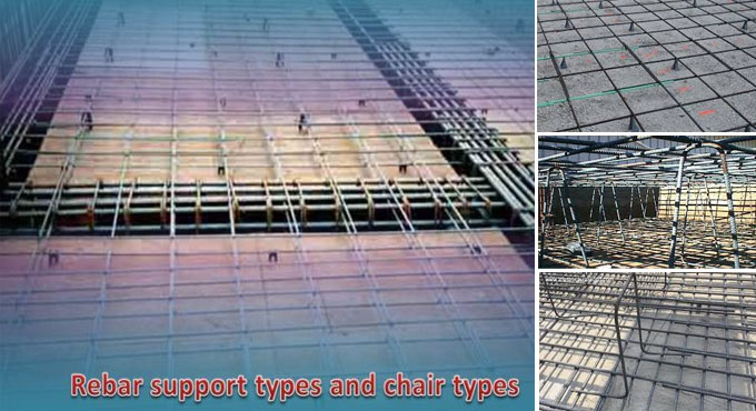
A rebar chair also known as rebar spacer stands for a rebar support device that tie the rebar in exact location and in required spacing before the concrete is poured. These supporting devices are treated as essential part of the permanent structure and implanted in the concrete.
Types of Rebar Support - The following types of rebar supports are commonly used:
1. Rebar Chair Support or Stools
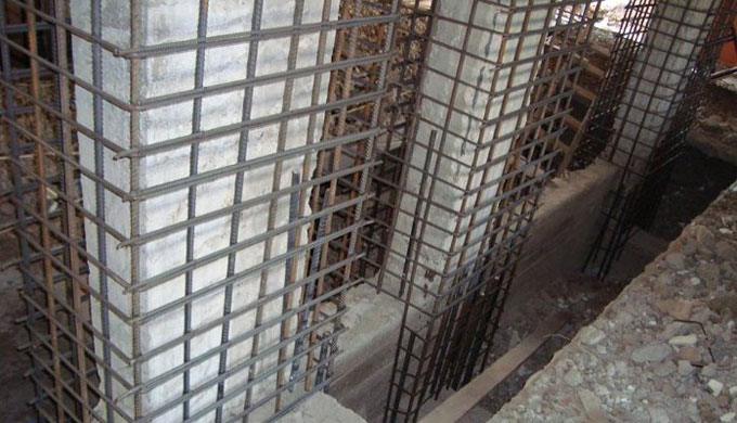
2. Rebar Spacer Support
The word Rebar Chair is generally applied for support system towards reinforced concrete slabs, floors, sidewalks or driveways; they uplift the rebar off the ground by securing its position and arranging the necessary cover from the ground. If the slab contains multi-layers of rebar, these chairs should comprise of slots for two or three layers as per the structural design.
Rebar spacers stand for those types of rebar supports which are found in reinforced concrete walls, columns, piers or piles etc. They fix the vertical and horizontal rebar in exact location with the center to center clearance among various layers of rebar as well as arrange the necessary cover from the edge of the formwork.
Rebar Support Variations: The flat bottom chairs are also available to avoid the chair tips from suspending the vapor barrier and retaining a more secure surface.
Steel chairs with plastic tips cab also be used. They are cost-effective and can be utilized when small spots of erosions are found on the surface. Stainless steel chairs also exist, but they are little expensive as compared to traditional chairs, and when plastic can’t be provided into the concrete or when the weight is heavy for the plastic chairs.
Rebar Support Problems: Often, chairs will be overturned, when necessary cover is in excess of 2.5 inches, since the height to width ratio is insufficient, to facilitate the workers from walking over.
Besides, when they are too far away, the rebar will bend in the middle because of its weight, and extra chairs will be needed for some areas or the chairs can actually rupture owning to extreme weight. Some steel chairs having a plastic tip might untie the plastic protection all through the installation process, providing a feasible area on which corrosion can occur and the concrete surface will be damaged.
Details about Rebar Support and Chair Spacing

~~~~~~~~~~~~~~~~~~~~~~~~
Published By
Rajib Dey
www.constructioncost.co
~~~~~~~~~~~~~~~~~~~~~~~~

Tuesday, March 27, 2018

Some useful notes on steel structure

Sami Ullah, the eminent engineer, presents another useful video tutorial for civil engineering students. This video provides detail information on steel structures.

Standard bar splices (lapping length for the steel) for tension member applicable to all members :-


For nos #3, 4 and 5 bars splice length is = 12 inches
For no #6 bar splice length = 22 inches
For no #8 splice length = 40 inches
General notes:
All the positive (bottom) reinforcement is demonstrated as solid lines in the drawing.
All the negative (top) reinforcement as a dashed alias broken line in the drawing.
Clear cover for slab = 0.75 inches
Clear cover for beam = 1.5 inches
Clear cover for column = 1.5 inches
Clear cover for foundation = 2.5 inches
The applied concrete should contain a minimum 28 day’s cylinder crushing strength of 3000 psi.
Splice length of steel for M20 concrete :-
Slab = 60d
Column = 45d
Beam = 60d
Here, d denotes dia of steel that is utilized in a slab.
To get more details, watch the following video tutorial.
Video SourceSami Ullah

~~~~~~~~~~~~~~~~~~~~~~~~
Published By
Rajib Dey
www.constructioncost.co
~~~~~~~~~~~~~~~~~~~~~~~~

Thursday, November 2, 2017

Some useful tips for making inspection of reinforcement in jobsite

Though the inspection of reinforcement involves lots of complexities and huge cost, but the problem should be properly resolved by appointing a standard consulting firm for accomplishing the inspection work.

The first step should be checking drawing. One must have adequate knowledge for analyzing a rebar drawing. The field engineers should have proper knowledge & capability to communicate with it in the jobsite.

To become an efficient rebar checker, practice for reading drawings on a regular basis. For this purpose one should gather proper knowledge with the steel rebar binding process. Given below, some useful tricks provided by some top peers who have lots of experience in this field :-

It is suggested to carry a measuring tape with yourself all the times for the purpose of examining the spacing and the splice or development length.

One should have clear conception on physical features of the construction component i.e. if some type of drainage pipe or electrical conduit should be set up or water stopper should be substituted or any other pipes / implanted item should be arranged.

Initially, the diameter of rebar should be examined properly through a vernier caliper. The other important things which should be examined thoroughly are rebar spacing, rebar development length, lap / splice length, alignment, no sag or buckling present in the bars, the couplers should be perfectly set and tightened, bars should be perfectly fixed, there should not be any rust on the bars, check for proper clear cover, no of bars should be computed properly and be similar with the drawings and should not be under or over 2 bars which are arranged there.

Always take suggestions from the contractor’s foreman or site engineer for the placement of the bars.
One should have sound knowledge with the steel quality tests like tensile strength check or torsion failure strength or coupler tension strength check etc. Make sure that the applied steel is taken from the verified lot and must not be a failed quality.
Though proper execution of design becomes very complicated because of inconsiderate field conditions and difficultly in installation / fixing of rebars, but always ensure the design of reinforcement is completely perfect as improper design can lead to failure of a building if fully neglected / violated.
Always keep in mind that the orientation of bars like main rebars should be under the distribution or temperature rebars. It can be verified from the drawings delivered to you.
Some useful tips for making inspection of reinforcement in jobsite

~~~~~~~~~~~~~~~~~~~~~~~~
Published By
Rajib Dey
www.constructioncost.co
~~~~~~~~~~~~~~~~~~~~~~~~