adsense analytic

Showing posts with label Reinforcement Steel. Show all posts

Thursday, April 11, 2019

Some vital guidelines to build up a raft foundation

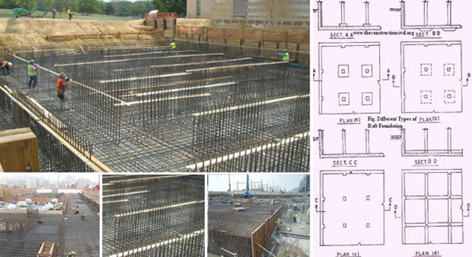
A raft foundation alias mat foundation refers to a continuous slab that stands on the soil that expands over the whole footprint of the building, thus provides strong support to the building as well as transmits its weight to the ground.
A raft foundation is mostly suitable when the soil becomes weak, since it allows to allocate the weight of the building over the whole area of the building, and not over shorter zones (like individual footings) or at individual points (like pile foundations). It minimizes the stress on the soil.
Stress is merely the weight divided with area. As for instance, when a building measures 5 x 5 weighs 50 tons, and contains a raft foundation, then the stress on the soil is weight / area = 50/25 = 2 tons per square meter.
When the similar building is supported by 4 individual footings with dimension 1 x 1m each, then the entire area of the foundation should be 4 m2, and the stress on the soil should be 50/16, that is around 12.5 tons per square meter. Therefore, if the entire area of the foundation is raised, the stress on the soil is significantly reduced, that means the weight per square meter.
A raft foundation is also effective for basements. Foundations are built up with excavation of soil with the purpose of retaining strong, compact, undisturbed natural soil that remains a few feet underneath ground level.
This soil contains more strength as compared to the loose soil at the surface. When a raft foundation is built up 10 feet under ground, and the concrete walls remain around the boundary to form a sound basement.
GUIDELINES TO BUILD UP A RAFT OR MAT FOUNDATION
Initially, excavate the ground to consistent, flat level to build up a raft foundation.
After that, place a waterproof plastic sheet over the earth, and pour a thin 3" layer of plain cement concrete (PCC) to form a rightly flat and level base for the foundation.
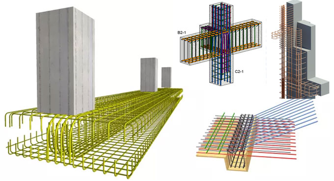
Then, a waterproofing layer is set up, and then reinforcement steel for the raft slab is secured in place. Once all the steel are arranged in exact location, concrete is poured to the required thickness that normally remains in the range of 200mm (8") to 300mm (12") thick for small buildings. The thickness will be increased when it is required to combat heavy loads.
To get more details, click on the link.
Some vital guidelines to build up a raft foundation

~~~~~~~~~~~~~~~~~~~~~~~~~~
Published By
Rajib Dey
www.constructioncost.co
~~~~~~~~~~~~~~~~~~~~~~~~~~

Monday, July 16, 2018

Bar Bending Schedule For Floor Slabs

Bar bending schedule is an important structural working document that rightly gives the disposition, bending shape, total length, and quantity of all the reinforcements that have been provided in a structural drawing.

It is often provided in a separate sheet (usually A4 paper) from the structural drawing.

The bar marks from structural detailing drawing are directly transferred to the bar bending schedule. We normally quantify reinforcements based on their total mass in tonnes or kilograms. For smaller projects, you can quantify based on the length needed.

Unit mass of rebars
The unit mass of the reinforcements is obtained from the density of steel. The density of steel provided for this purpose is 7850 kg/m3.
Suppose, there is a bar with 12mm dia;
The area is calculated by (πd2)/4 = (π × 122)/4 = 113.097mm2 = 0.0001131m2
Based on a unit length of the bar, it is established that the volume of a metre length of the bar is 0.0001131m3.
Density = Mass/Volume = 7850 kg/m3 = Mass/0.0001131
So, the unit mass of 12mm bar = 7850 × 0.0001131 = 0.888 kg/m
So, for any diameter of bar;
Basic weight = 0.00785 kg/mm2 per metre
Weight per metre = 0.006165 ϕ2 kg
Weight per mm2 at spacing s(mm) = 6.165ϕ2/s kg
Here;
ϕ denotes diameter of bar in millimetres
Bending Shapes
There exist some basic standard shapes with specific shape codes in the code of practice.
The length of reinforcement bars can be determined with the following relation;
Length of bar = Effective Length + Width of Support – Concrete cover (s) – Tolerances
The standard values of tolerances (deductions) are provided in the table below;
To get more details, go through the following link structville.com
Bar Bending Schedule For Floor Slabs

~~~~~~~~~~~~~~~~~~~~~~~~
Published By
Rajib Dey
www.constructioncost.co
~~~~~~~~~~~~~~~~~~~~~~~~

Tuesday, June 19, 2018

Some useful tips for reinforcement detailing

Given below, some useful tips for reinforcement detailing :-

Create drawings perfectly. Try to mark every bar and demonstrate its shape for transparency.

Cross section of retaining wall that falls quickly as soon as soil backfill is arranged since ¼” dia is used instead of 1 ¼” dia. Errors happen as exact rebar dia is covered with a dimension line.

If required, generate bar bending schedule.

Denote perfect clear cover, nominal cover or effective cover to reinforcement.

Settle detailed location of opening/hole and provide sufficient information for reinforcement around the openings.

Utilize the size of bars and spirals which are easily accessible. For a single structural member, there should limited numbers of various sizes of bars.

The grade of the steel should be mentioned properly in the drawing. Deformed bars should not contain hooks at their ends.

The enlarge details at corner, intersections of walls, beams and column joint should be demonstrated at identical situations. There should not be congestion of bars at points where members overlap and ensure that all reinforcements are placed perfectly.

For bundled bars, lapped splice of bundled bars should be formed by connecting one bar at once; such separate splices inside the bundle should be staggered.

Ensure that the hooked and bent up bars are arranged and there is sufficient protection for concrete.

Specify all expansion, construction and contraction joints on plans and provide details for such joints.

The position of construction joints should be at the point of minimum shear roughly at mid or adjacent to the mid points. It should be created vertically instead of a sloped manner.

Article Source: onlinecivilforum.com

Some useful tips for reinforcement detailing

~~~~~~~~~~~~~~~~~~~~~~~~
Published By
Rajib Dey
www.constructioncost.co
~~~~~~~~~~~~~~~~~~~~~~~~

Thursday, June 7, 2018

Various types of notations used in the construction of concrete culvert design

The following notations are used in the drawing of concrete culvert design.

With notation, it is possible to make clear communication among various project stakeholders. Notation helps in avoiding mistakes in any construction project.

A’ = The valid contact area of a footing, measuring unit is in square metres
A = A detailing dimension for culverts that contains skewed ends, measuring unit is in mm
B = Depth of the bottom slab of a box culvert, measuring unit is in mm
B = Gapping among adjoining bars with reference to detailing tables, measuring unit is in mm
C = A coefficient that is applied in finding out the quantities of reinforcing bar.
CANBAS = Canadian Bridge Analysis System
c’ = the valid cohesion among the base of the footing and the soil at the ULS, with reference to CHBDC. kPa
CHBDC = Canadian Highway Bridge Design Code, 2000 Edition
CGSB = Canadian General Standards Board
F = Width of footing for open footing culverts, measuring unit is in mm
F1 = A reinforcing bar spacing factor, measuring unit is in mm-1
HULS = maximum factored horizontal reaction at the level of the base of the footing at the ULS, kN
Lc = Culvert length that is calculated the longitudinal axis, measuring unit is in m
OCPA = Ontario Concrete Pipe Association

OMBAS = Ontario Modular Bridge Analysis System
OPSS = Ontario Provincial Standard Specifications
S = Culvert distance that is calculated perpendicular to the longitudinal axis of the culvert, measuring unit is in mm
SLS = Serviceability limit states, in accordance with CHBDC

T = Depth of top slab of culvert, mm tan φ’ effective friction coefficient for concrete cast against soil.
ULS = Ultimate limit states, with reference to CHBDC
V = Unfactored vertical reaction because of the dead load of cast-in-place concrete and soil fill, at the level of the base of the footing, kN
VSLS = Maximum vertical reaction at the level of the base of the footing at SLS, kN

VULS = Maximum factored vertical reaction at the level of the base of the footing at ULS, kN
W = Depth of wall of culvert, measuring unit is in mm
Γ = The extreme angle among the normal to the longitudinal axis and the end of the same culvert, degrees
φ’ = The valid angle of internal friction, with reference to CHBDC, measuring unit is in degrees
θ = Skew angle of culvert, degrees


Various types of notations used in the construction of concrete culvert design

Read more

~~~~~~~~~~~~~~~~~~~~~~~~
Published By
Rajib Dey
www.constructioncost.co
~~~~~~~~~~~~~~~~~~~~~~~~

Tuesday, February 27, 2018

Variation among Lap Length and Development Length (Anchorage)

The reinforcement bars are mainly arranged to transmit the load from member to member i.e. either to another rebar or to concrete.

To transmit the load from one member to another securely & efficiently, reinforcement bars should have been tightly attached at both ends to resist skidding of the bars.

Lap Length: Lap length stands for the length of the overlap of bar necessary for securely delivering stress from one bar to another. Lap length varies in case of tension and compression zones and primarily based on concrete and steel. When, it is required to lap bars with various dia, the length is dependent on smaller dia.

The rebars are available in specific length. If the rebar has to be expanded apart from that limit, then there should be adequate lap length to safely transfer the load.

Lap length varies on the basis of tension (at bottom of a beam) and compression zones (at top of beam) and various factors like grade of concrete, rebar size, concrete cover etc affect the lap length.

Development Length: Development length stands for the length of the bar essential to transmit stress from steel to concrete.

As per IS456, the computed tension or compression in any bar at any section should be developed on each side of the section with an accurate development or by end anchorage or with a combination thereof.

As per IS 456:2000, the computed tension or compression in any bar at any section should be formed on every side of the section with proper development length or with an end anchorage to resist skidding of the member from the support.

Such length should be arranged in a continuous beam, cantilever slabs and other critical joints (beam-column). It will be supplied as a bend where the restraining member is thin similar to an end beam as demonstrated under (Ld).

Article Source: www.civilology.com

Variation among Lap Length and Development Length (Anchorage)

~~~~~~~~~~~~~~~~~~~~~~~~
Published By
Rajib Dey
www.constructioncost.co
~~~~~~~~~~~~~~~~~~~~~~~~

Friday, May 12, 2017

How to compute quantity of steel in column footing with BBS

This construction video tutorial will teach you how to estimate the steel quantity in column footing with bar bending schedule.

Column Footing stands for an independent footing or foundation under a column or either equivalent member for delivering the concentrated load by means of uniformly loads to the soil underneath in order that the bearing capacity of the soil is not surpassed and differential settling does not take place. The footing may come in square, rectangular or circular in plan.

The footing may be constructed with brick masonry, stone, R.C.C., steel grill-age etc on the basis of the load to be transferred as well as the bearing capacity of soil. As a result of low bending strength, the footings built with brick, stone or plain concrete need extensive depth to bear heavy loads safely.


The depth of plain concrete footing is minimized significantly with the arrangement of reinforcements at its base to withstand tensile stresses. R.C.C. column footings may com in circular, rectangular or square in plan. The footing is reinforced both-ways using mild steel ribbed bars which are arranged at exact angles to one another at similar distances apart.


Read more

~~~~~~~~~~~~~~~~~~~~~~~~
Published By
Rajib Dey
www.constructioncost.co

~~~~~~~~~~~~~~~~~~~~~~~~