adsense analytic

Showing posts with label Concrete Design Wall. Show all posts

Thursday, June 7, 2018

Various types of notations used in the construction of concrete culvert design

The following notations are used in the drawing of concrete culvert design.

With notation, it is possible to make clear communication among various project stakeholders. Notation helps in avoiding mistakes in any construction project.

A’ = The valid contact area of a footing, measuring unit is in square metres
A = A detailing dimension for culverts that contains skewed ends, measuring unit is in mm
B = Depth of the bottom slab of a box culvert, measuring unit is in mm
B = Gapping among adjoining bars with reference to detailing tables, measuring unit is in mm
C = A coefficient that is applied in finding out the quantities of reinforcing bar.
CANBAS = Canadian Bridge Analysis System
c’ = the valid cohesion among the base of the footing and the soil at the ULS, with reference to CHBDC. kPa
CHBDC = Canadian Highway Bridge Design Code, 2000 Edition
CGSB = Canadian General Standards Board
F = Width of footing for open footing culverts, measuring unit is in mm
F1 = A reinforcing bar spacing factor, measuring unit is in mm-1
HULS = maximum factored horizontal reaction at the level of the base of the footing at the ULS, kN
Lc = Culvert length that is calculated the longitudinal axis, measuring unit is in m
OCPA = Ontario Concrete Pipe Association

OMBAS = Ontario Modular Bridge Analysis System
OPSS = Ontario Provincial Standard Specifications
S = Culvert distance that is calculated perpendicular to the longitudinal axis of the culvert, measuring unit is in mm
SLS = Serviceability limit states, in accordance with CHBDC

T = Depth of top slab of culvert, mm tan φ’ effective friction coefficient for concrete cast against soil.
ULS = Ultimate limit states, with reference to CHBDC
V = Unfactored vertical reaction because of the dead load of cast-in-place concrete and soil fill, at the level of the base of the footing, kN
VSLS = Maximum vertical reaction at the level of the base of the footing at SLS, kN

VULS = Maximum factored vertical reaction at the level of the base of the footing at ULS, kN
W = Depth of wall of culvert, measuring unit is in mm
Γ = The extreme angle among the normal to the longitudinal axis and the end of the same culvert, degrees
φ’ = The valid angle of internal friction, with reference to CHBDC, measuring unit is in degrees
θ = Skew angle of culvert, degrees
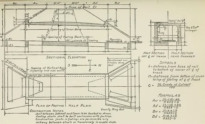

Various types of notations used in the construction of concrete culvert design

Read more

~~~~~~~~~~~~~~~~~~~~~~~~
Published By
Rajib Dey
www.constructioncost.co
~~~~~~~~~~~~~~~~~~~~~~~~

Friday, May 4, 2018

Structural Design of ASDIP Concrete

ASDIP Concrete is a set of modules which are fully devoted for the design of concrete members like beams, columns and walls depended on the newest ACI 318 specifications.

These specifications can explain the time wasting calculations in any type of structural engineering office; while this ASDIP Concrete 3.1.7v is developed by ASDIP Structural Software and can perform well with Windows. This is a trial version and the file size of the downloaded version is about 4.85 MB.


Here is the list of things which are found under this ASDIP Concrete:

Modules of ASDIP Concrete: This concrete is a unified, merged system that has a combination of flexibility of a fill-in-the-blanks format with the power of Windows Forms and both of them can easily develop either an optimal design or a fast investigation. ASDIP Concrete uses a screen with tabbed pages to enter the users’ data directly onto the forms and allow seeing the results instantly which helps to control the design process, to get the detailed results and the graphics easily.
User Interface: The software uses pull-down menus, dialog boxes and in-field editing as the primary user interface, all these components help to manage and control the difficult design algorithms easily and transparently to the end user in a simple way. It also approves the input data to stop wrong format and users can automatically develop their design with the text-with-values output messages which are updated with every change.
Project Manager: It is a very important thing in the ASDIP Concrete System which takes care of both the calculations and files management from where anyone can create, copy, delete or print calculations, create and save projects and arrange the work.
Reports: The concrete creates high quality previously formatted reports with particular information of any design and optimize the design with the graphical interface, then print preview the results and finally print the report.
Trial Limitations:
• Report- Print disabled
• File- Save Disabled
• 15 day assessment period


ASDIP Concrete has the design of following types of concrete elements:


• Concrete Columns: The design of a concrete column under the action of axial loads and bending moments; while this module can calculates the enlarged moments for slimness of ASCE 7 load combinations and creates the column strength interaction diagram.
• Concrete Beams: The design of a concrete multi-span regular beam under the action of uniform and concreted loads while this module specifically calculate the bending and crop strength for various types of beams and load combinations per ASCE 7.
• Bearing Walls: The design of a concrete wall under the action of vertical and out-of-plane literal loads; the module calculates the magnified moments for slimness of ASCE 7 load combinations and creates the wall strength interaction plan.
Here is some similar software of ASDIP Concrete:
ASDIP Foundation: It is a set of modules certainly dedicated to the design of concrete footings depended on the newest IBC/ACI 318 specifications that simplify calculations of the wasted time in any structural engineering office.
ASDIP Retain: It is a set of modules dedicated fully to the design of retaining walls depended on the new IBC/ACI 318 specifications to simplify the time consuming calculation in any structural engineering office.
ASDIP Steel: It is a set of modules dedicated fully to the design of structural steel members depended on the new AISC 360 for simplifying the time taking calculations in any structural engineering office.
ASDIP: It is a 13-module structural ser with a board of design solutions for new structural engineers.
Advance Concrete: It is totally designed for engineers and structural draftsmen for total and easy to use software fully integrated into AutoCAD.
ASTRUTTIE: It is a strut-tie model design software for concrete members with disturbed stress regions.


Download Free 15 days Trial: asdipsoft.com/asdip-concrete
~~~~~~~~~~~~~~~~~~~~~~~~
Published By
Rajib Dey
www.constructioncost.co
~~~~~~~~~~~~~~~~~~~~~~~~

Tuesday, October 17, 2017

How to settle density of various masonry walls in buildings

On the basis of loads and other factors, the density of masonry walls in a building is designed. Given below the details of perfect thickness of masonry walls necessary at the design phase :-

As for instance, it is suggested to utilize invariable masonry wall thickness among lateral supports. The lateral support for masonry is arranged with cross walls, pilasters, and structural frame members.

Concerning deviation of masonry in vertical direction, the distance among floors, structural frames and roofs should be taken into consideration if the density of masonry wall is different.
Masonry wall thickness modifies among floor and roof as well as various floors that is generally imposed to attain thermal, sound and fire requirements.
If the density of masonry wall is modified, it is suggested to expand the thicker wall to the lower support level.
Building code requirements and specifications for masonry structure (ACI 530-11) affirms that, when the density of masonry wall is developed hollow masonry units is modified, then it is necessary to arrange a layer or various layers of solid masonry units or entirely grouted hollow masonry units among the thicker masonry wall and the thinner masonry wall.
The objective of arranging solid masonry course among thicker and thinner masonry wall should be transmitting loads perfectly from the above wall (thin wall) to the wall underneath (thick wall).
There are various constraints and limitations which should be taken into consideration for masonry walls apart from the case where the walls are designed for reinforcements on the basis of the engineering principles.
The constraint related to masonry thickness for various masonry walls types are explained in detail.
Thickness Requirements for Load Bearing Masonry Wall: The density of load bearing masonry wall should have been minimum 304.8 mm (1 ft.) dense for maximum wall height of 10.668m (35 ft.).
Besides, the density of masonry wall should be raised by 101.6 mm (4in.) for each consecutive 10.668m (35 ft.) height or fractions of this height calculated from the top of the masonry wall.
There are different cases in which the above conditions are not applicable for load bearing masonry walls which range from stiffened masonry wall, top storey masonry wall, residential masonry wall, masonry wall of penthouses and roof structures, plain concrete and grouted brick masonry wall, hollow masonry wall, faced masonry wall, nonbearing masonry wall.
How to settle density of various masonry walls in buildings

Read Continue

~~~~~~~~~~~~~~~~~~~~~~~~
Published By
Rajib Dey
www.constructioncost.co
~~~~~~~~~~~~~~~~~~~~~~~~