adsense analytic

Showing posts with label Method. Show all posts

Saturday, March 14, 2020

Advantages and Disadvantages of On-site and Off-site Construction

The needs and restrictions at your construction project may make you choose between one of the two main methods of construction: on-site and off-site. Both are widely used in today’s construction industry, depending upon the requirements at the site and according to design.

What is On-Site Construction?
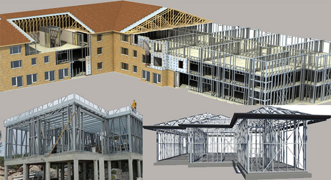
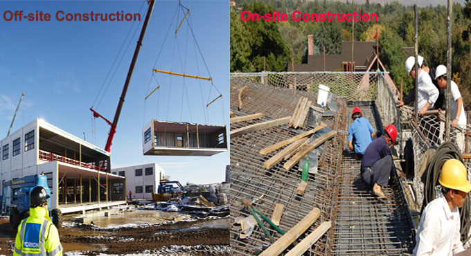
On-site construction is the more traditional method. Here, structures are assembled from raw materials at the site itself, hence the name. The method has to be carried out sequentially and materials needs to be stored and used at the site.


What is Off-Site Construction?
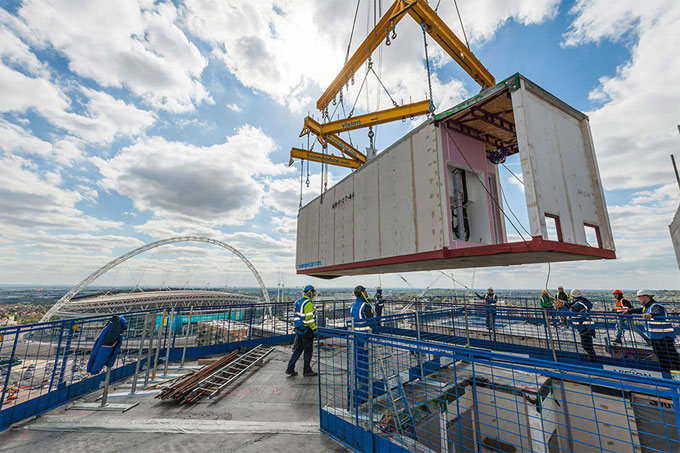
With modern technologies, off-site method of construction has become possible. In this, parts or blocks of the structure are constructed in a designated factory or yard in standardized process. Then, these pre-built blocks are carried to the project site where they are assembled together to form the structure.


Both of the above methods have their own advantages and disadvantages, which make them suitable to different scenarios. Let’s discuss them below.

On-Site Construction

Advantages:

1. Customized Design: Since there is no restriction on what shape of objects are available of construction, there are limitless customization options in this manner. In fact most non-standard designs have to rely upon the on-site method just for this.
2. Alteration: After the construction you can easily modify the structure with this method. It doesn’t require you to depend upon third-party construction factories to add or change a room in your house that has been constructed in the traditional method.
3. Space-friendly: Transporting precast blocks in tight urban areas can get simply impossible. More often, it’s prohibitively expensive. In these scenarios you have no choice but to construct everything on-site.
Advantages and Disadvantages of On-site and Off-site Construction

~~~~~~~~~~~~~~~~~~~~~~~~~~
Published By
Rajib Dey
www.constructioncost.co

~~~~~~~~~~~~~~~~~~~~~~~~~~

Monday, February 10, 2020

Using Light Gauge Steel Frames in Construction

There is a new construction method on the market, and it is quite cool. Called the Light Gauge Steel Frame Construction, it is successfully replacing the standard wood frame construction method. This innovative method is being widely accepted in many building designs and construction aspects.
The Light Gauge Steel Frames offer several advantages. Some of them are design flexibility, strength, sustainability, buildability, etc. This makes Light Gauge Steel Frames easier to build and much safer too. Not only that, it is also faster to build. Word to the wise, though - the light steel frame is susceptible to fire, so fire protection coating needs to be provided.
Based on ASTM standard A1003, Light Gauge Steel Frames are manufactured from structural steel sheets. These sheets are formed into ‘C’ ‘Z’ and ‘S’ shapes. This makes the structure strong and able to support heavy loads. It is also called cold formed steel. This is because of the process by which it is manufactured.
This added strength and flexibility leads Light Gauge Steel Frames to support increased spans. They can be shaped into custom openings. Moreover, they can support many different types of external facade treatments. This sheer versatility is making the Light Gauge Steel Frames very popular among modern constructors.
One thing to be noted about Light Gauge Steel Frames is they are much more susceptible to corrosion effects than standard wooden frames. For this reason, they have to be provided with zinc, aluminum or combo coatings to make them corrosion-resistant over long periods.
Using Light Gauge Steel Frames in Construction
~~~~~~~~~~~~~~~~~~~~~~~~~~
Published By
Rajib Dey
www.constructioncost.co
~~~~~~~~~~~~~~~~~~~~~~~~~~

Friday, December 13, 2019

Five Reasons Why Off-site Modular Construction is the New Favorite

What is Off-site Modular Construction
Up until the last decade, we have always known construction business is to be conducted on project site. However, with the advent of technology, a new method of building has come up. This is called Off-site Modular Construction, and it is shaking the construction industry at the roots.
In this process, portions of a building are constructed in remote factories or fields that are specifically set up for that purpose. They are built using the same design and materials - but since they are being built in a factory for that express purpose, the construction takes about half the time. These “modules” are then carried off to the project site and are assembled there to reflect the original design of the entire project.
Growth in Modular Construction Business
There has been an increased demand for off-site modular construction, ever since the construction industry has rebounded up since 2013. Experts project that the market has progressed by 26% between 2014 to 2017.
An estimate is that the projected growth for the period 2018 to 2020 is by 4% every year. Such promising verticals can be associated with the resurgence in sectors such as education, offices, and retail. It is also a gift from with increased market for locality accommodation on infrastructure projects.
Architects, developers, and constructors are all gradually becoming aware of the plethora of benefits offered by technological innovations associated with the modular construction industry. From hotels, retail, offices, public buildings, apartment blocs to simple homes - all sorts of construction projects can be assembled with offsite modular structures.
This method of building is a favorable alternative to regular on-site construction, and it is durable and cost-effective. The main reason for that is the offsite modular building offers great quality and flexibility. It is also faster to finish the project with fewer expenses. Also, when it comes to counting the environmental impact and guaranteeing sustainability, there is no match for off-site construction methods.
Five Reasons Why Off-site Modular Construction is the New Favorite

~~~~~~~~~~~~~~~~~~~~~~~~~~
Published By
Rajib Dey
www.constructioncost.co
~~~~~~~~~~~~~~~~~~~~~~~~~~

Monday, August 5, 2019

Factor of safety for soil bearing capacity

Factors of safety for bearing capacity refers to a value that is based on the basis of the type of soil, method of exploration, level of uncertainty in soil, significance of structure and outcomes of failure, and probability of design load proceeding.
So, it creates adequate space to adapt uncertainties and potential over loading throughout the duration of the structure and its foundation through the cutback of ultimate bearing capacity of soil to permissible bearing capacity.
The permissible bearing capacity is measured by dividing ultimate bearing capacity with factor of safety. Normally, a factor of safety of (3) is presumed for bearing capacity calculations, if not mentioned for bearing capacity problems.
Bearing capacity means the strength of soil to bear the pressure securely that is provided on the soil from any engineered structure devoid of experience a shear failure with accompanying large settlements. Applying a bearing pressure that is secured with regards to failure does not guarantee that settlement of the foundation will remain inside tolerable ranges.
So, settlement analysis should normally be accomplished since most structures are sensitive to extreme settlement.
In the following table, you will get the standard factor of safety for bearing capacity calculation in different conditions. These factors of safeties are conservative and normally limit settlement to suitable values, but economy may be abandoned in some cases.
Factor of safety chosen for design is based on the extent of information obtainable on subsoil characteristics and their variability. A detailed and wide-ranging subsoil investigation may allow use of smaller factor of safety.

Factor of safety for soil bearing capacity

~~~~~~~~~~~~~~~~~~~~~~~~
Published By
Rajib Dey
www.constructioncost.co
~~~~~~~~~~~~~~~~~~~~~~~~

Saturday, July 13, 2019

Inspection & Testing Method of concrete

This civil engineering article focuses on the test method required for evaluating the concrete work.
Concrete construction activities should be done on the basis of the job site specifications, methods and drawings. Concrete inspection and testing should be executed by experienced personnel to ensure that requirements of the specifications, methods and drawings are satisfied.
Tests of concrete is conducted to make sure that the compliance to specifications should be performed by a certified Concrete Field Testing Technician.
If not mentioned anywhere else in the specifications and/or drawings, at least six concrete cubes should be developed and treated as a set. If not mentioned anywhere else, the cubes will be tested in the following ways :-
2 cubes at 7 days
2 at 28 days
2 held in reserve
The results obtained from the test, should be noted on a spreadsheet and in a way conformable to QC procedure: Statistical Techniques.
Unless stated otherwise in plan specifications or drawings, one set of cube should be created for each 150 cubic yards of concrete laid as defined in building codes. Minimum one set of cubes should be formed on each day concrete is laid irrespective of the quantity of concrete.
Application of QC procedures: Process Control as a guide, Contractor should fix a meeting with the subcontractor before pouring the first concrete. This meeting will be conducted so that the subcontractor can narrate his/her plans for the concrete pour along with all the areas scheduled in this section of the procedure.
Batch Plant Inspection: Contractor retains the power to examine any and all concrete batch plants which will deliver concrete to the construction site. A “walk through” inspection should be carried out before the production of concrete is started.
If it is required, examinations can be done throughout concrete production. Given below, the major inspection items for every type of batch plant inspection:
Preliminary Inspection
• Check that aggregates are loaded in exact bins
• Examine that aggregates are not polluted
• Examine that scales and measuring devices contain current calibration stickers and seem to function perfectly
• Examine that the plant contains a current local authority approval certification
• Examine that concrete trucks remain in proper working condition
• Examine that entire operation of the plant seems to be professional, systematic, relatively clean, well maintained, etc.
• Examine that batch plant operators should have adequate knowledge (verify their certificates or certifications)
• Examine that batch tickets provide crucial information (amount of hold back water, list of ingredients, batch times, size of load, indication of mix ordered, etc.)
• Examine that the plant and delivery equipment can form homogeneous concrete as per the requirements of ASTM C-94
• Make sure that the plant and delivery equipment satisfy the capacity requirements of the job
Throughout Concrete Production (if necessary):
• Examine that correct mix has been loaded into the batch plant computer
• Examine that equipment is working properly (admixture dispensers, scales, moisture indicators, etc.)
• Examine that truck counters have been reset to zero once the mixing water has been added to the mix
• Examine that water used to “wash down” the concrete truck prior to leaving the plant area does not enter the concrete mix
• Examine that the amount of hold back water is stated on the batch ticket
• Make sure that the concrete coming out from the plant will satisfy the specifications for temperature, air content and slump (testing at the plant should be conducted if required)
Concrete Mix Design: All proposed concrete mixes should be provided to Consultants via main contractor for verification and approval before application. The projected mixes delivered for use shall comprise of a concrete strength break history as stated in ASTM and shall include suitable test results and/or certificates of conformance on all constituents which will be applied in the certain concrete mixes.
Inspection & Testing Method of concrete

~~~~~~~~~~~~~~~~~~~~~~~~
Published By
Rajib Dey
www.constructioncost.co
~~~~~~~~~~~~~~~~~~~~~~~~

Tuesday, July 2, 2019

Benefits of I-beams in construction

Hot-rolled steel beam having I-shaped cross section, and tapered flanges closer than wide flanged beam is known as I-beam.
I Beam contains one vertical plane and two horizontal planes or flanges which develop 'I' or 'H' structure. The vertical plane withstands the shear stress , whereas horizontal planes withstand the bending movement. I Beam is majorly utilized in construction industry like construction of manufacturing plants, multi-story buildings etc.
I-beam is frequently applied as important support trusses, or the primary framework, in buildings. Steel I beams retain structure’s integrity with persistent strength and support. The extreme power of I beams minimizes the requirement for several support structures and as a result huge time and money is saved. The stability of the structure is improved considerably.
Some vital jargons of I-Beam:
1. Flange thickness: Top and bottom horizontal plate-like segments of an I-beam are known as flange. The density of the flanges is defined as the flange thickness.
2. Flange width: The width of the flanges is known as flange width.
3. Beam depth: The height among the top and bottom surface of the steel I beam is termed as beam depth.
4. Web thickness: The vertical segment of steel I beam is known as web, and the thickness of the web is termed as web thickness.
5. Fillet radius: The curved section, where the changeover among the web and flange occurs is known as a fillet. The radius of the fillet is defined as the fillet radius.
A properly sized I Beam can be chosen on the basis of the following criterion :-
The entire method of choosing the proper size of the I beam is dependent on the basic mechanical design calculations as given below:
1. The first input necessary belongs to the steel I beam load specifications or loading details on the steel I beam.
2. Draw bending moment diagram for the specified loads and get the value of maximum bending moments (suppose M) that the steel I beam is likely to experience.
3. Select an exact size of steel I beam from a standard I beam table.
4. Determine the area moment of inertia (suppose I) of the selected steel I beam.
5. Obtain the beam depth (suppose d) of the selected steel I beam.
6. The stress developed (f) in the beam can be measured with the formula given below :
f/(d/2)=M/ I
f denotes the bending stress.
M denotes the moment at the neutral axis.
y denotes the perpendicular distance to the neutral axis.
I denotes the area moment of inertia about the neutral axis x.
7. Compare the calculated value of the bending stress with the yield stress of the steel with the purpose of verifying the safety factor of your design.
The structural design will be perfect when the size of the I-beam is accurate. The method described above is dependent on static I beam load specifications. In case where dynamic loads are concerned, it is necessary to apply FEA tools like ANSYS, Pro Mechanica, etc.
Benefits of I-beams in construction

~~~~~~~~~~~~~~~~~~~~~~~~
Published By
Rajib Dey
www.constructioncost.co
~~~~~~~~~~~~~~~~~~~~~~~~

Friday, June 28, 2019

Details about Ultrasonic Pulse Velocity

This test is conducted for the purpose of evaluating the concrete quality with ultrasonic pulse velocity method with adherence to IS: 13311 (Part 1) – 1992. The underlying principle of this test is –
Under this method, testing is done by sending an ultrasonic pulse through the concrete and time of movement is calculated. Relatively, greater velocity exists if the quality of concrete is good with respect to density, consistency, homogeneity etc.
The following method is applied to ascertain the strength of hardened concrete with Ultrasonic Pulse Velocity :-
i) Making it ready for use: Prior to changing to the ‘V’ meter, the transducers should be attached to the sockets leveled as “TRAN” and ” REC”.
The ‘V’ meter is activated with either: a) the internal battery, b) an external battery or c) the A.C line.
ii) Set reference: A reference bar is arranged to examine the instrument zero. The pulse time for the bar is inscribed on it. Prior to set it on the opposite ends of the bar, provide a coat of grease to the transducer faces. Fine-tune the ‘SET REF’ control unless the transit time of reference bar is captured on the instrument read-out.
iii) Range selection: For greater precision, it is suggested that the 0.1 microsecond range should be chosen for path length upto 400mm.
iv) Pulse velocity: After detecting the exact test points on the material to be tested, thorough measurement of the path length ‘L’ should be done. Provide couplant to the surfaces of the transducers and press it firmly onto the surface of the material.
It is suggested not to shift the transducers at the time of taking a reading since noise signals and errors in measurements may occur. Keep on retaining the transducers onto the surface of the material unless a reliable reading is shown on the display that is the time in microsecond for the ultrasonic pulse to pass through the distance ‘L’. The mean value of the display readings should be captured while the units digit follows among two values.
Pulse velocity=(Path length/Travel time)
v) Partition of transducer leads: It is recommended to avoid the two transducer leads from getting in touch with each other at the time of taking the transit time measurements.
If it is not performed, the receiver lead will pick-up unnecessary signals from the transmitter lead and it leads to an wrong display of the transit time.
Interpretation of Results
The quality of concrete with regard to consistency, occurrence or nonexistence of internal faults, cracks and segregation, etc, indication of the level of workmanship provided, can thus be examined with the following guidelines which are changed for defining the quality of concrete in structures with regard to the ultrasonic pulse velocity.
Details about Ultrasonic Pulse Velocity

~~~~~~~~~~~~~~~~~~~~~~~~
Published By
Rajib Dey
www.constructioncost.co
~~~~~~~~~~~~~~~~~~~~~~~~

Tuesday, June 25, 2019

Methods of concrete cube test

In concrete compression test, generally the concrete cube samples with dimensions 150mmx150mmx150mm are utilized. But, in place of 150mmx150mmx150mm concrete cube samples, 100mmx100mmx100mm concrete cube samples are applied for the test.

Fundamentally, the force produced through a concrete compression machine is a definite value. For the use of normal concrete strength, suppose under 50MPa, the stress provided by a 150mmx150mmx150mm cube is adequate for the machine to smash the concrete sample.

However, when the intended concrete strength is 100MPa, under the equivalent force (about2,000kN) delivered by the machine, the stress under a 150mmx150mmx150mm cube is inadequate to crush the concrete cube.

So, 100mmx100mmx100mm concrete cubes are used in place of 150mmx150mmx150mm cubes to raise the used stress to crush the concrete cubes. For normal concrete strength, the cube size of 150mmx150mmx150mm is already sufficient for the crushing strength of the machine.

Cube Test:

Instrument And Material.

Concrete cube mould with size 150mm or 100mm is applied for aggregate size of not more than 40mm and 25mm. Cube mould for test should be formed into steel or cast iron containing smooth inner surface. Each mould should contain steel plate to support and avoid leakage.

Compacting steel rod should be used with 16mm diameter and 600mm length.

The test should be conducted by compression test machine.

Method: Mould and base plate should be cleansed and employed with oil so that the concrete can’t fix to the side of the cube. Base plate is affixed to the mould with bolt and nut.
The cube should be filled with concrete in three layers.

Each layer should be consolidated for 25 times. This process should be accomplished systematically and compaction should be finished equally to all the surfaces of the concrete. Compaction is also done with machine.

The surface of concrete should be leveled to retain the equivalent level with the upper side of the mould.

Cubes which are produced at construction site should be wrapped with plastic cover for a period of 24 hours prior to remove the moulds.

After remoulded, the concrete cubes should be drowned in water for curing.
Compression strength test should be conducted for concrete at age 7, 14, and 28 days through compression test machine.

Result: The Strength value of each cube should be noted and compared with the targeted strength value. The reason for conducting the concrete test on 7 th day and the 14 th day is to anticipate whether the concrete could attain the targeted 28 th day strength. Normally, concrete can obtain 70% strength on the 7 th day.


Methods of concrete cube test

~~~~~~~~~~~~~~~~~~~~~~~~
Published By
Rajib Dey
www.constructioncost.co
~~~~~~~~~~~~~~~~~~~~~~~~

Friday, April 5, 2019

Some crucial tips to check the quality of Fe 500D TMT bars

To make your house stronger, it’s vital to use standard quality of the TMT bars which build up the foundation of your constructions. Fe 500D rods are considered as the most safe and quality bars in the market to safeguard your homes against natural disasters whereas providing the flexibility and greater strength for your house.

Given below, some useful tips to verify the quality of the Fe 500D rods obtainable in the market.

1. Manufacturing Brand: Collect proper information for the manufacturers of the TMT bars to get a fair idea concerning their specific production cycle, quality tests they maintain for the exacting quantities of sulphur, phosphorus and carbon in the Fe 500D grade, and the number of years they are in the market. It becomes easier to rely on a brand after understanding their method and manufacturing guidelines and how strictly they abide by the quality standards set out. So, it is recommended to purchase from the dealers who are affiliated with such trusted brands.

2. Quality check reports: Top brands maintain quality as well as detailed reports from top laboratories to reveal their dedication to retain the perfect quality of their products. So, such brands provide logical reports on their raw materials with their dealers which are accessible for you to examine and understand. With these trustworthy reports on the exacting factors of raw-material quantity, consistent quality of the Fe 500D rods, process compliance for the greater rods, etc, you are more intimated about the products to be purchased which form the basic foundation of your homes and other constructions.

For the Fe 500D variant, the quantities of sulphur, phosphorus, and carbon are essential for the quality of the rods and they should not go beyond the following amounts in the reports, according to the BIS prescriptions:

Carbon level: 0.25
Phosphorus level: 0.045
Sulphur level: 0.045
Phosphorus and Sulphur combined levels : 0.080


3. Symbol of Certification: Each industry is verified for quality standards and the brands and companies who stringently abide by the guidelines are awarded with a symbol of trust through the relatable tags and marks. For the Steel industry, the standard BIS mark demonstrates the superior quality in the products and processes of the manufacturing industry. This mark is found for each product provided by such a company. Search for such certification marks to make sure that the quality products are purchased from your dealers.

4. Trusted Dealer: Dealers or sales representatives associated with quality brands can be trusted to provide quality products for your requirement. If purchase is made from sensible dealers who are liable for gathering all crucial reports for the raw-materials, processes, etc whereas conducting their own tests and research to produce quality products. Check all the reviews and comments about the dealers from other builders and customers who have already purchased the products from them earlier to take an up to date decision.

By undertaking all these steps, make sure that the products to be purchased are not only give value for money but also impart the long-term protection of the Fe 500D TMT rods promise. Fe 500D bars that satisfy all the required guidelines are accredited with the respected BIS mark.

Some crucial tips to check the quality of Fe 500D TMT bars

Read Continue

~~~~~~~~~~~~~~~~~~~~~~~~~~
Published By
Rajib Dey
www.constructioncost.co
~~~~~~~~~~~~~~~~~~~~~~~~~~