adsense analytic

Showing posts with label retaining walls. Show all posts

Friday, February 14, 2020

What are Shear Keys and How to Use Them

A building and structure has to bear not only vertical loads, but also lateral loads. This can occur due to many design or natural reasons. To counteract this lateral load, Shear Keys are used. Let us see today what exactly are shear keys and how can you use them in your construction.
A building can face a lot of lateral load due to many reasons. Some of these include earthquake loads, sliding forces, water pressure, wind pressure etc. This often occurs with bridges, retaining walls, basements, extremely tall buildings, precast buildings and culverts, masonry walls where seismic activity is stronger, and steel columns and piers.
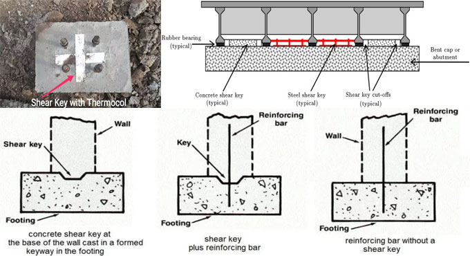
Shear keys can be constructed by concrete in precast buildings, and of steel in steel structures. Sometimes, steel reinforcements are made to play the part of shear keys as well. They improve the lateral stability of a building.
Placement of Shear Keys: Where the shear keys will be placed differs a lot depending upon the structure they need to support. Let us discuss them below.
Bridges: In small to medium bridge structures, shear keys are placed in the abutments of the bridge. This provides lateral transverse support to the structure above during sidewise movement.
During an earthquake or similar strong lateral force application, the shear keys act as a sacrifice. Therefore, the strong seismic forces are prevented from entering the abutment piles.
They act better when they are placed on the outer side of the bridge. However, this makes them difficult to inspect or repair.
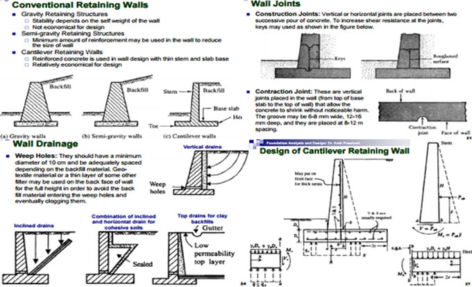
Retaining Walls: You should place shear keys at the base of retaining walls, just beneath the stem. This prevents sliding of the base during strong lateral force application.
The shear keys placed beneath the wall must be nearly twice in width than their depth for the best performance. Generally, they are 508mm by 381 mm, respectively.
What are Shear Keys and How to Use Them
~~~~~~~~~~~~~~~~~~~~~~~~~~
Published By
Rajib Dey
www.constructioncost.co
~~~~~~~~~~~~~~~~~~~~~~~~~~

Wednesday, June 12, 2019

Some vital instructions to make your boundary walls stronger

Substandard foundations, poor design, scarcity of expansion joints and piers (support pillars) generally lead to cracks in masonry boundary walls.

If a subsisting wall is inclined, unsteady or contains severe cracks, then proper remedies should be taken immediately.

Given below, some vital guidelines while setting up a new boundary wall:

1. The design of the wall: Besides, adhering to local by-laws concerning height restrictions and set-backs on street corners, proper engineering principles should also be applied to the design of any freestanding wall.

Both the thickness of the wall and the spacing of piers control the maximum height of the wall over ground level.

2. Foundations: While creating the design of the foundations, soil conditions and slopes should be considered. Steel reinforcement of the foundations and of the wall itself are vital components. A general rule of thumb is that the foundation should be broader and deeper so that the support of the wall becomes more stable.

3. Retaining walls: When the boundary wall functions as a retaining wall and is susceptible to water and soil thrust, then the foundation footing should be expanded more beneath the upper side of the wall to make sure that the weight of the chosen soil further firm ups the foundation structure.

4. Adequate expansion joints and piers: If expansion joints are not set up perfectly without adequate piers, the walls can be cracked easily.

If there are cavities in the piers of freestanding walls (along with hollow units), they should be filled with concrete instantly.

5. Drainage: If the boundary wall is located on a slope, then sufficient weep holes should be installed to dispose of accumulated storm water.

When the wall also functions as a retaining wall, there should proper arrangement of sub-soil drainage. NHBRC (Part 3. 3:24) indicates that weep holes should be set up in all retaining walls at a height not greater than 300mm over the lower ground level at centres not surpassing1.5 metres. Weep holes should be created with a 50mm plastic pipe covered on the non-exposed end with a geofabric.

6. Damp: Boundary walls are generally freestanding as these walls do not usually build section of a structure (like a house), where the connected walls are self-bracing. Since the freestanding walls are not supported by a structure of other walls, boundary walls are normally constructed exclusive of a damp proof course (DPC), plastic membrane so as to make the bond stronger among the freestanding wall and its foundation.

A DPC can rupture the bond among wall and foundation that leads to instability. Without DPC, mounting damp is frequently found on plastered and painted boundary walls. To get rid of this issue, the harder (less porous) bricks should be used for the lower courses (first 150mm) and make sure that the plaster does not expand to the level of the soil, else the plaster will function as a wick and allow water going from the ground to wick upwards.


Some vital instructions to make your boundary walls stronger

~~~~~~~~~~~~~~~~~~~~~~~~
Published By
Rajib Dey
www.constructioncost.co
~~~~~~~~~~~~~~~~~~~~~~~~

Saturday, September 1, 2018

Concept of retaining wall designing

Retaining Wall: If it is required to provide support to an excavated area or a lower area of minimum 1 or 1.2 meters or more from a lifted section of the soil, a retaining wall should be set up there. This type of structure is suitable to withstand the lateral pressure resulting from the soil.

The retaining walls are generally constructed in the basement part of a building structure. While applying as integral to basement walls, they are frequently utilized as a support for floor diaphragm and a return wall that build them too rigid for active soil pressure to form necessary higher design loads and a dissimilar design approach.

The design of retaining wall is based on the following mode of failures:

Retaining Wall Mode of Failures

1. Overturning: The retaining wall under overturning failure easily collapses in bending.

2. Sliding: Retaining wall that collapses because of sliding often contain non-cohesive soils. The walls shift outer with a passive failure of soil ahead of foundation and active failure of soil back the wall. Many times a key is necessary under the foundation to stop sliding.

3. Bearing Check: Bearing check should be done because of the failure when the soil remains under the toe of the foundation and a forward rotation of the wall.

4. Overstress on any part of the Retaining Wall happens because of either bending or shear.

5. General Stability. It is a obstruction on slope failure, overall stability, and base stability.

Concept of forces in Retaining Walls: Exclusive of the self-weight, weight of soil and weight caused by the water it carries, the lateral soil pressure on the walls also requires to take into account.

The allocation of pressure P is similar to the area under the pressure distribution figure, and its line of action moves through the centroid of the pressure. While calculating earth pressure on walls, three common conditions of loading are usually taken into account.

2. Surcharge: A surcharge belongs to a Horizontal surface of fill that bears a uniformly distributed surplus load as a result of an adjoining neighbor or road traffic.

The pressure due to surcharge measured by transiting its load equivalent, an imaginary height of soil h’ over the top of the wall is stated as h=s/ɣ.

To get more detail, go through the following link thestructuralworld.com

Definition and categorisation of Pre-Stressed Concrete


~~~~~~~~~~~~~~~~~~~~~~~~
Published By
Rajib Dey
www.constructioncost.co
~~~~~~~~~~~~~~~~~~~~~~~~

Saturday, November 18, 2017

How to design reinforced & unreinforced concrete and masonry gravity retaining walls as per Euro & BS codes

MasterKey Retaining Walls Design provides the most extensive program that can be used for creating the design of both reinforced and unreinforced concrete and masonry gravity retaining walls as per Eurocode 7, BS 8002, BS 8110, CP2 IS 325 and BS 5628 Part1 and Part2. Highways design by adhering to BD 30/87 & BD37/01 is also comprised.

The users can easily use MasterKey Retaining Walls with a short learning curve.


With it’s collaborative nature, it is possible to instantly view the effects of inserting loads, piers, ties and props, rectifying reinforcement as well as the wall geometry or soil properties. MasterKey Retaining Walls offers you complete control over the design method, allowing you to improve the efficiency of the wall.
• Design Codes: British, Irish & Eurocode design
• Concrete retaining wall design
• Masonry retaining wall design
• Cavity, bed-joint and pocket reinforcement in masonry walls
• Design to Eurocode 7, BS 8002 or CP2
• Design to Highways BD 30/87 & BD 37/01
• Stiffened and unstiffened walls including buttressed and counterfort walls
• Layered soil modelling
• Water table and horizontal surge force
• Cohesive and granular soils
• Sloped or stepped front and back faces
• Upstand above top of soil
• At rest earth pressure
• Multiple props, ties and spring supports
• Line loads on wall, base and embankment
• Partial distributed surcharges
• Exports DXF details
• Exports details to MasterRC for AutoCAD
• Schedules using the MasterRC Scheduler
In order to download a full functioning 30-days trial version, click on the following link masterseries.com

~~~~~~~~~~~~~~~~~~~~~~~~~
Published By
Rajib Dey
www.constructioncost.co
~~~~~~~~~~~~~~~~~~~~~~~~~

Thursday, March 23, 2017

Different types of Loads and Forces functioning on Retaining Wall

Retaining wall design will contain any or all of loads and forces which are briefly described in the following sections:
1. Lateral earth pressure
2. Surcharge loads
3. Axial loads
4. Wind on projecting stem
5. Impact forces
6. Seismic earth pressure
7. Seismic wall self-weight forces
1. Lateral Earth Pressure Functioning on Retaining Wall
The primary objective of developing a retaining wall is to hold the soil. For this reason, soil lateral earth pressure is a vital factor in the design. Among various theories, sliding soil wedge theory is mostly recognized for measuring the lateral earth pressure.
The wedge theory implies that a triangular wedge of soil will fall down if retaining wall is disconnected unexpectedly and the wall has to withstand this wedge soil. From the Figure 1, we can view free body lateral forces performing on retaining walls.
Different types of Loads and Forces functioning on Retaining Wall
Coulomb and Rankine equations belong to most vital formulas which are used to compute lateral earth pressure:
The Coulomb method of Lateral Earth Pressure Calculation
This equation considers backfill slope, friction angle at wall face, rupture plan angle, and internal friction angle etc.
Different types of Loads and Forces functioning on Retaining Wall
Where:
Ka : coefficient of active pressure
Angle of internal friction
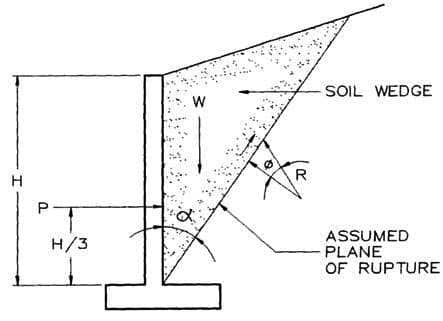
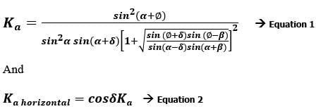
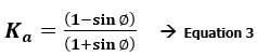
: Angle of internal friction
Angle of backfill slope: Angle of backfill slope
Angle of friction among soil and wall: Angle of friction among soil and wall (2?3Angle of internal friction to 1?2Angle of internal friction is supposed)
Slope angle of the wall: Slope angle of the wall that is calculated from horizontal (same as 90 degree for vertical wall)
Besides, concerning flat level backfill soil, observing zero friction at soil-wall interface, and soil-sidewall is vertical, the coulomb equation is contracted to the following:
Different types of Loads and Forces functioning on Retaining Wall
To read the complete article, go through the following link.
theconstructor.org
~~~~~~~~~~~~~~~~~~~~~~~~
Published By
Rajib Dey
www.constructioncost.co
~~~~~~~~~~~~~~~~~~~~~~~~