adsense analytic

Showing posts with label Road Construction. Show all posts

Wednesday, December 26, 2018

Variations among Wet, Moist, and Damp Subgrade

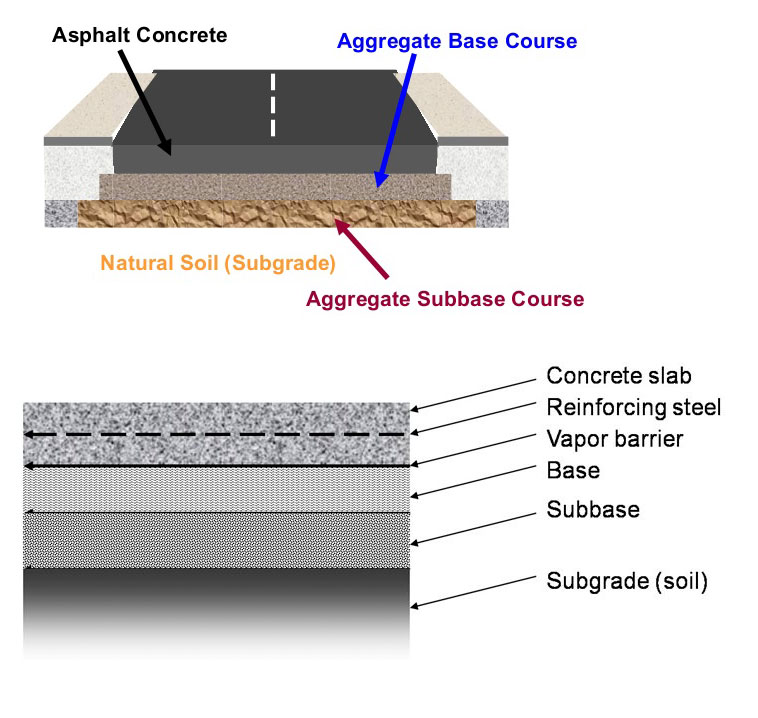
Subgrade is taken as the most vital element of the pavement structure as it functions as a foundation for other pavement elements which are developed upon it and resist detrimental influences of weather and various traffic loads.

The performance of subgrades is significantly impacted with unstable water content. Hence, it is essential to examine the behaviour of subgrade under several conditions. Under this condition, wet, moist, and damp subgrade are identified on the basis of the water quantity in the subgrade components.

The concerned engineers should have clear conceptions on the variations among wet, moist, and damp condition and how the strength of pavement structure is influenced by them. The bearing strength, shrinkage, and swelling of subgrade are mostly affected by the moisture content. Given below, the detail information about the variations among wet, moist, and damp subgrade.

Wet Subgrade

  1. As per ACI 116R-90, wet condition happens when the material comprises of apparent free moisture.
  2. It is the indication of maximum level of moisture.
  3. Wet subgrade is majorly damaged under loads.
  4. Wet subgrade tolerates severe swelling and shrinkage and due to this pavement deforms and cracks.
  5. Wet subgrade is not recommended for pavement construction. Therefore, so it should be upgraded with proper method.
  6. When the roads are built up on such subgrade devoid of correct advancement, then future maintenance work is necessary.

Moist subgrade

  1. As per ACI 116R-90, if the material is mildly coated with moisture, the moist condition occurs.
  2. There is mild moisture among wet and dump.
  3. Bearing strength performance is superior as compared to wet subgrade but lower than damp subgrade.
  4. Swelling and shrinkage of moist subgrade and flaws of pavement above occurs to some extent among damp and wet subgrade.
  5. It is suitable for pavement construction but a slight advancement is required.
  6. Less costly improvement is applied to get rid of future maintenance.
Damp subgrade

  1. As per ACI 116R-90, damp condition happens if the material is marginally dump but not gets dry to the touch Specifies lowest level of moisture.
  2. Damp subgrade functions well with regard to load bearing strength as compared to wet and moist subgrade.
  3. It is not affected with swelling and shrinkage significantly, and therefore the damage is not adequate to the pavement.
  4. It is ideal for pavement construction.
  5. It does not need any improvement and future maintenance is inexpensive.
To get more detail, go through the following link theconstructor.org

Variations among Wet, Moist, and Damp Subgrade

~~~~~~~~~~~~~~~~~~~~~~~~
Published By
Rajib Dey
www.constructioncost.co
~~~~~~~~~~~~~~~~~~~~~~~~

Thursday, October 4, 2018

Details of Sand Compaction Piles

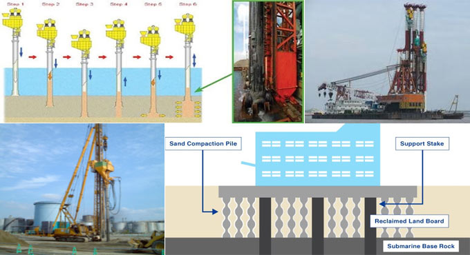
Sand compaction piles provide lots of benefits like enhancing the durability of ground, controlling liquefaction, minimizing settlement and equivalent applications. Under this system, a hollow steel pipe is pushed into the ground. The bottom is ceased with a collapsible plate down to the necessary depth and then pipe is stuffed with sand. The pipe is detached when the air pressure is driven opposing the sand inside it.

The bottom plate opens throughout removal and the sand backfills the vacuums formed previously at the time of pushing the pipe. The sand backfill resists the soil that encircles the compaction pipe from falling while the pipe is withdrawn. All through this process, the soil is solidified.

Based on the system provided, two types of sand compaction piles exist. One is vibratory system having vibro-hammer and another is a non-vibratory system having forced lifting or driving device.

The vibro-hammer that is utilized in this method can create problem with vibration and noise to the encompassing environment. So, it is not recommended to apply this method in the urban areas or at areas adjacent to existing structures.

To get rid of these issues, a system with a non-vibratory Sand compaction pile method should be employed that does not need vibration on the driving device to infiltrate into the ground. The equipment comprises of a sand compaction pile driving device that is applied as a base machine and a forced lifting or driving device containing a rotary drive motor to revolve the casing pipe.

Non-vibratory Sand compaction method:

• Arrange the casing pipe to the planned location.
• With the use of the forced lifting or driving device, set up the casing pipe into the ground at the time of rotating.
• The sand is supplied through upper hopper as soon as the pipe attains the necessary depth.
• Casing pipe is pulled up and as a result the sand is pressed out to the void with compressed air.
• The casing is then removed together with the compaction of the pressed out sand pile to expand it.
• The method is reiterated unless the sand piles are created to the ground surface.


Design of sand compaction piles is based on the following factors :-

• Strength of the sand column
• Piles and soil are responsible for equivalent vertical deformation


Pros and cons of sand compaction piles: The main benefit of these sand piles is that the sand used is inexpensive as compared to other similar ground improvement methods like stone columns.

The construction process of the sand columns is very quick. Once, the hole is formed, it’s completely supported by casing throughout construction that restrains the chance of collapsing the structure.

Sand compaction piles contains a low stiffness with regards to other methods. So, the greater quantity of weak soil should be replaced. These piles do not contain adequately high permeability to function since effective vertical drains all through earthquakes.

Sand compaction piles are useful for making pervious embankment foundations stronger against liquefaction or impervious foundations against durability issues during an earthquake.

Details of Sand Compaction Piles

Read more

~~~~~~~~~~~~~~~~~~~~~~~~
Published By
Rajib Dey
www.constructioncost.co
~~~~~~~~~~~~~~~~~~~~~~~~

Monday, May 7, 2018

Various types of Design Loads on Bridges, Highway & Rail Bridge

While going to deign any bridge, the tasks like computation of Design Loads and loading bridge model are very important. Given below, some crucial loads which should be taken into consideration at the time of creating the design of a bridge.

Dead Load - “Gravity loading because of structural parts of bridge”
Dead load comprises of permanent gravity forces because of structural Elements. It is basically measured as the product of volume and material density. Normally, self-weight is employed in the analysis model with the self-weight option of the analysis software. This makes the calculation step simple.
Superimposed Dead Load - “Dead Gravity loading because of non-structural parts of bridge”
Superimposed dead loads stand for gravity loads that include other permanent items ranging from parapets and road surfacing and other non-structural and architectural attachments to the bridge. Such items last long but should have been modified during the lifetime of the structure. It has similarity with self-weight and it is measured as the product of volume and material density.
The most crucial item of superimposed dead load belongs to the road pavement or surfacing. It is not atypical for road pavements to become gradually thicker over a number of years since every new surfacing is just placed on top of the one before it. Therefore, specifically high load factor is employed to road pavement.
Imposed traffic Loading - “Because of road or rail vehicles”
Imposed traffic loads contain those forces which are produced with road or rail vehicles on the bridge. Bridge traffic can be vehicular, rail or pedestrian/cycle or genuinely any combination of these. The type and strength of the design vehicle alters on the basis of the design code. As for instance, HL-93 is used in AASHTO design code.
Bridge traffic loading is frequently monitored by trucks whose weights significantly surpass the maximum legal. Bridge traffic loading is used with the notional lanes which do not depend on the actual lanes. Eurocode normal loading comprises of invariable loading and a pair of four wheels in a single lane.
To examine the dynamic effects of traffic, the vehicular loads are multiplied with an impact factor frequently.
Pedestrian and cycle track - “Gravity loading because of non-vehicular traffic”
Bridge codes normally indicate a basic intensity for pedestrian loading. Again intensity is based on the design code, it is 5 kN/m2 in the Eurocode and the British standard and 4 kN/m2 in the American code.
To get more detail information, go through the following link. engineeringcivil.org


~~~~~~~~~~~~~~~~~~~~~~~~
Published By
Rajib Dey
www.constructioncost.co
~~~~~~~~~~~~~~~~~~~~~~~~

Wednesday, November 8, 2017

Guidelines for site layout or job layout at construction site

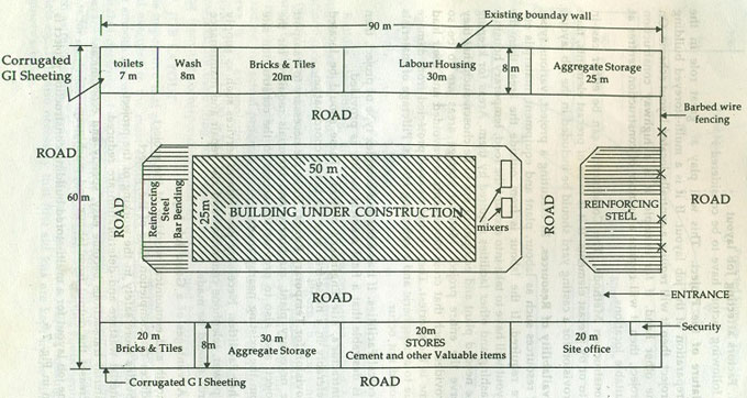
Site layout refers to the plan of the construction site. It provides the area as well as the proper position for arranging the necessary resources in the construction work.

It specifies the place for offices, godowns, workshops, accommodation etc. It also illustrates the present relationship of the site with its surrounding with regards to communication, approaches and existing facilities.


Given below the importance of a systematic and technically organized site layout :-
1. Obtain an uninterrupted supply of materials in adequate amount.
2. Get a smooth access to material and test out its wastage and degradation.
3. Reduce the number of plants as well as the movement of heavy equipment.
4. Prevent confusion and minimize accidents.
5. Keep a systematic viewpoint for easy inspection of the materials.
The layout that fulfills most of these conditions enhances efficiency along with productivity. Such a layout is recognized as optimum layout. The site layout is mainly based on the following factors.
1. Position of the site, 2. Arrangement of space, 3. Access to the site, 4. Material volume, 5. Type of applicable equipment, 6. Ground conditions.
Fundamentals of jobs layout: The following fundamentals should be maintained for job layout.
1. If possible, there should be two openings in the site, one for entry and the other for exist to allow flow of traffic. For the existence of only one gate, then it is preferred to arrange a cross-over near the gate.
2. The general office should be situated adjacent to the main gate to stay away from confusion at construction site.
3. The godown should be situated just at the back of the general office so that the delivery of the material is accumulated in it. It also allows a tighter supervision of the stores.
4. Temporary roads should have been built up around the operation area. It makes the flow of material as well movement of equipment better. In reality, if such roads are essential to be built up in the project, it is suggested to build them initially in order that these can be utilized throughout the construction accurately.
5. The workshops for joiner, fitter, electrician etc should be determined and placed by balancing the easy and short access routes..
6. Staff accommodation should be far from noise. It should be centralized in one area to facilitate communication and trim down the cost of facilities and services.
7. The existing services should be used as far as possible.
Guidelines for site layout or job layout at construction site


~~~~~~~~~~~~~~~~~~~~~~~~~
Published By
Rajib Dey
www.constructioncost.co
~~~~~~~~~~~~~~~~~~~~~~~~~