adsense analytic

Showing posts with label engineer. Show all posts

Monday, August 12, 2019

Calculation of buckling for pinned column

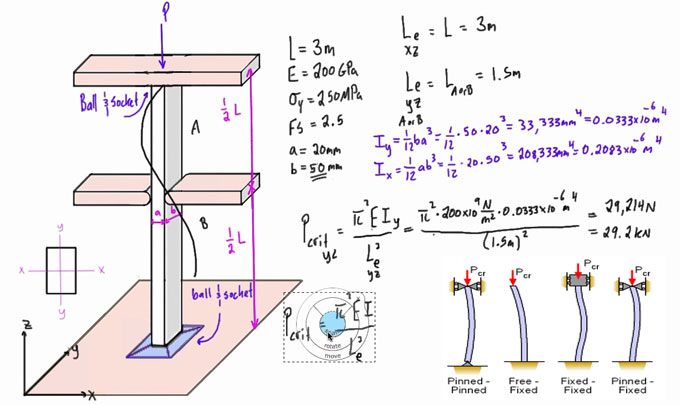
For the ideal pinned column, the critical buckling load is computed with Euler's formula:
                                                                                             Calculation of buckling for pinned column
Here:
E stands for Modulus of elasticity of the material
I stands for Minimum moment of inertia
L stands for Unsupported length of the column.
It should be remembered that irrespective of the end condition, the critical load is based not only on the material strength, but also on the flexural rigidity, EI. Buckling resistance is raised by enhancing the moment of inertia.
If a column buckles, it retains its deflected shape once the critical load is enforced. In most applications, the critical load is normally considered as the maximum load tolerable by the column. Theoretically, any buckling mode is feasible, but the column will ordinarily deflect into the first mode. A column will buckle when the load P attains a critical level, known as the critical load, Pcr.
For columns containing several types of support, Euler's formula may is useful when the distance L is substituted with the distance among the zero moment points. See "Effective Length Constant Table" below.
This length is known as the effective length Le and is demonstrated with the following equation:
Calculation of buckling for pinned column
The slenderness ratio is a vital parameter in the classification of compression members, and is demonstrated with the following equation:
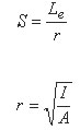
Calculation of buckling for pinned column
Here:
r stands for Radius of gyration
I stands for Moment of inertia
A stands for Area cross section
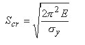
If the slenderness ratio remains (greater than) critical slenderness ratio, then the column is considered as a long column and the Euler buckling formula will be as follow :-
If slenderness ratio remains less than the critical slenderness ratio, the column is considered as a short column.
Calculation of buckling for pinned column
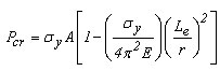
In short columns, failure may happen by compression devoid of major buckling and at stresses surpassing the proportional limit. For this condition, Johnson's formula will be used :
Calculation of buckling for pinned column
For columns which collapse following the onset of inelastic behavior, the constant of proportionality should be utilized in spite of the modulus of elasticity (Engesser formula). The constant of proportionality, Et, refers to the slope of the stress-strain diagram beyond the proportional limit, known as the tangent modulus. Note within the linearly elastic range, E = Et.
To calculate column buckling, use the following online calculator engineersedge.com
Calculation of buckling for pinned column

~~~~~~~~~~~~~~~~~~~~~~~~
Published By
Rajib Dey
www.constructioncost.co
~~~~~~~~~~~~~~~~~~~~~~~~

Thursday, May 16, 2019

Types of reinforcement or mesh in several footings (foundations)

Different types of Reinforcement in footings or types of mesh used in foundation:-

Several types of reinforcement exist in footings. The reinforcement should be provided in footings for tension requirements. Normally, the percentage of reinforcement in footings should remain among 0.5% to 0.8%. Based on the load analysis, the structural engineer design the type of Mesh in footings. Given below, the details about he types of mesh (reinforcement) implemented at several types of footings or foundations.

Usually, four different types of reinforcement in footings or foundations are found :–

1. Plain Mesh: This type of Mesh is normally implemented at plain or isolated or combined footings. It is specifically useful for low-rise buildings. Prior to use plain mesh to high rise buildings, the load should be analyzed in accordance with this mesh and determine either the type of mesh is balanced with the load or not.

Under this type, bars are arranged as a grid. It may contain bars with various diameter and spacing in either direction. The spacing may or may not vary in both directions.

2. Mesh with hooks (Hook Mesh): It is suitable for both low rise and high rise buildings. The footing is reinforced as grid and the bars are arranged with hook at the ends of the mesh. The perfect anchorage of the reinforcement can be obtained by bending the bars ends. Normally, the standard length of hook is 10D where D stands for the diameter of the bar.

3. Footing Mesh up to the depth of Footing: It has similarity with Plain footing. Under this type of footing, the bars are bent at ends up to a height of footing. The concrete cover of 1″ to 4″ should be arranged in all the sides of footing.

4. Raft Mesh: This type of Mesh is ideal for raft footing. Raft footing is suitable when the bearing strength of soil is very low. Under this type, mesh is segregated into two parts like top mesh and bottom Mesh.

Initially, the bottom mesh is arranged on covering blocks, ends of a bottom mesh are bent at an angle of 90 degree up to a height of 50D where D stands for Dia of Bar. After that top mesh is attached with the bottom mesh in opposite direction. Besides, the top mesh equivalent to bottom mesh is bent with 90 degrees but an additional bar of 50D is not arranged since it is already equipped on bottom mesh.

The 50D extra bar is arranged either on bottom or top mesh.

Single ring or double rings are attached with top mesh and bottom mesh to retain the proper framework. The rings allow the steel reinforcement not to distort in any direction. Least diameter of bars used for rings should be 6 mm.

In single ring raft mesh, rings are arranged in only one direction either horizontal or vertical, while in double ring system, the rings are arranged in both the direction.

The following points should be taken into consideration :-

1. Concrete cover differs from 1" to 4" depending on the size of the footing.
2. Hook length in Hook mesh is always 9D, where D stands for Dia of bar.
3. Additional bar is arranged either on top or bottom mesh and additional bar length is 50D.


Types of reinforcement or mesh in several footings (foundations)

Read more
~~~~~~~~~~~~~~~~~~~~~~~~
Published By
Rajib Dey
www.constructioncost.co
~~~~~~~~~~~~~~~~~~~~~~~~

Saturday, May 11, 2019

How to perform audit of old structures

There exist several types of public buildings with over 30 years lifespan. The stability of these buildings is decreased significantly owing to decay in materials.

On the basis of the yearly tests conducted on each public building, the weaker buildings having age over 30 years should be detected and the Assistant Executive Engineer level Officer of the related department should dispatch the list to the superior officer of the level.

Then, an inspection at the level of superintending Engineer/EE should be performed for all such building and an extensive structural audit should be carried out.

The related department should hand over the structural audit to an accredited Institution / agency and the details of which are provided below:

Usually, the Structural Audit should be performed with the following steps:

Step 1: The Architectural and Structural plans of the building are important. There should be detailed structural calculations along with assumptions for the structural design.

Step 2: When the Architectural plans and Structural plans do not exist, the similar should be arranged on the basis of site observations.

Step 3: A building should be examined thoroughly as follow :-

1. Any settlement in the building.
2. Cracks found in columns, beams and slabs.
3. Pictures of concrete disintegration and exposed steel reinforcements are useful.
4. Slight tapping with a hammer can disclose decay in concrete and wooden beams.


5. Erosion in reinforcement.
6. Status of Balconies – sagging, deflection, cracks.
7. Status of Architectural features.
8. Cracks in walls specifying swelling in R.C.C members or identification of erosion.
9. Leakages from terrace & Toilet blocks.
10. Leakages & dampness in walls which lead to cracks and corrosion.
11. Status of repairs & last repaired date.
12. What section of the structure was repaired?
13. Who was the Agency?
14. How much was incurred for repairs?
15. Are sanctioned Building plans available?


Step 4: Formulation of Audit Report:
Depending on the inspection on building, the Audit Report should be arranged.


Step 5: Tests Suggested:
It is vital that different types of tests are performed in the old buildings to get an idea about spreading of corrosion, distress and loss of strength in concrete & steel.


Step 6: Point out the major areas and repair them accordingly.

How to perform audit of old structures

Read more
~~~~~~~~~~~~~~~~~~~~~~~~
Published By
Rajib Dey
www.constructioncost.co
~~~~~~~~~~~~~~~~~~~~~~~~

Wednesday, October 19, 2016

Concrete Footings – Some useful guidelines

Usually, it should be examined when the footings are arranged for concreting i.e. reinforcement is completely engrossed but it is recommended to examine it in two phase i.e.

01. Initially verify formwork prior to arrange reinforcement. This is very useful because finding out & rectifying formwork defect is very difficult once the reinforcement is organized in position.

02. Checking reinforcement – Therefore, it is suggested to initially verify the formwork prior to place or tie reinforcement.

01. Centering and shuttering / Formwork:

While starting the shuttering & centering / formwork for footing , abide by the following points.

  • Verify the center lines / margin from boundary etc. from reference column/bench mark pillar, boundary distance from roads and obviously orientation regarding North.
  • Make sure that the foundation is laid at a designed depth according to drawing.
  • Size of formwork box should be according to drawing and it should be formed with correct materials.
  • The formwork should have been dry and be refined cautiously prior to use mould release agent. The similar type of release agent should have been applied through on identical formwork materials.
  • The surface of formwork should have been uniform and delicately coated with mould release agent.
  • The mould release agent should not be contacted with reinforcement or the solidified concrete.
  • The height of shuttering must be similar with the height of pedestal and joint should have been closed to avoid any leakage of cement pulp.
  • Footing box should have been supported correctly in order that the placing of footing box should be unchanged throughout concreting.
  • Centre of the footing is stamped with the nail on planks or footing box.
  • Foundations shuttering should be strong in dry or even rainy situations or even when ground water exist.
  • Prior to tying reinforcement, get the shuttering sanctioned by Engineer-in-charge or supervisor.
  • Ensure that there is no earth collection on C.C. prior to tying reinforcement.
  • If foundation depth increases, make sure that the excavated earth does not slide or drop unless it is refilled. Accomplish perfect shoring and shuttering. Make sure that suitable ladder etc to enter the pit and for coming out. Besides, examine the safety of labor’s working.
To read the complete article, go through the following link gharpedia.com

Concrete Footings – Some useful guidelines

~~~~~~~~~~~~~~~~~~~~~
Published By
Rajib Dey
~~~~~~~~~~~~~~~~~~~~~

Friday, May 6, 2016

GRIDFORM™ Is An Advanced Concrete Reinforcing System For Vehicular Bridge Decks

GRIDFORM™ refers to a superior concrete-reinforcing system supported with prefabricated fiber reinforced polymer (FRP) double-layer grating and fundamental stay-in-place (SIP) form specifically designed for vehicular bridge decks.
This reinforcement system comprises of FRP plates glued to the bottom grating of FRP double-layer grating panels which produce a bidirectional, lightweight panel of the grid construction to be used with corrosion-free concrete bridge decks.
The lightweight GRIDFORM™ panel measures only 4.7 pounds per square foot. It is fabricated in shop with very big units which are restricted only by shipping constraints to around 50 ft. by 8 ft.
In the jobsite, the GRIDFORM™ is elevated through a single pick of a crane and directly set in the girders of the bridge. The GRIDFORM™ panel is pre-engineered and completed so that it can be affixed quickly to the bridge girders and relevant concrete placement and forming. The GRIDFORM™ bridge deck lasts long as compared to the steel reinforced concrete bridge decks as FRP delivers a corrosion-free reinforcement system for the concrete.
GRIDFORM™ Design Guide
The GRIDFORM™ Design Guide offers proper guidelines to structural engineers to define if GRIDFORM™ can be substituted for steel rebar as the internal reinforcement system for reinforced concrete bridge decks. Any engineering firm or installation contractor can utilize GRIDFORM™ by adhering to Strongwell's Terms and Conditions.
The GRIDFORM™ Design Guide is based on Microsoft® Excel® version 2003 or 2007.
GRIDFORM™ Is An Advanced Concrete Reinforcing System For Vehicular Bridge Decks
~~~~~~~~~~~~~~~~~~~~~
Published By
Rajib Dey
~~~~~~~~~~~~~~~~~~~~~

Thursday, December 17, 2015

SAFI Bridge is a useful construction program to Analyze & design 2D and 3D bridge models

The SAFI Bridge program is very useful for engineers to study, validate, assess, generate and design large and complicated 2D and 3D bridge models having different types and sizes on the basis of standard or non-standard moving loads. With this construction program, the engineers can validate and design steel, composite, reinforced concrete, bridges together with pre-stressed bridge girders.

The SAFI bridge analysis component of the program is based on the autonomous and customary code and it contains incomparable graphical user interface.

The SAFI Bridge program contains the following features :-

• The program accomplishes numerous simultaneous or non simultaneous standard and non standard moving  loads analysis with plain and complicated procedures.
• The program consists of a wide-ranging library containing more than 25 standard trucks and a moving load    editor for user defined trucks and trains.
• The moving loads can be transmitted to selected elements of the model.
• Impact factors are assigned for a whole truck load or following a per axle basis along with lane loads. Axles can    be expanded on the basis of some bridge design codes like the CAN/CSA S6-06 code

• Lateral distribution factors toward moment, shear and deflection are substantiated.
• Envelopes of response are procured with the integration of moving loads, lane loads and non moving loads.
• Incremental analysis is performed considering staged constructions.
• Load factors are established automatically by the program while analyzing a subsisting bridge.
• The advanced query engine is applied to determine the relevant forces and utmost values at any point of the      structure

• SAFI Bridge facilitates the query analysis results and associated results at any point of the structure
SAFI Bridge can assess and design steel, composite, reinforced concrete, bridges together with pre-stressed bridge girders.

Download SAFI Bridge Sheet for visit to site

SAFI Bridge

~~~~~~~~~~~~~~~~~~~~
Published By
Rajib Dey
~~~~~~~~~~~~~~~~~~~~

Tuesday, November 10, 2015

Make precious design calculation with RC-spreadsheets package version 4B.2

RC-spreadsheets package version 4 are designed by adhering to both Eurocode 2 and BS 8110-1:1997. The most updated version alias 4B.2 contains enhancements regarding to punching shear, column design and pilecap design as well as resolving bug.

The advanced engineer will be greatly benefitted by obtaining the transparent and precise design calculations.

The post-graduates and newbie engineers can easily gather knowledge on concrete design and familiar with analyzing 'what if' scenarios.

The individual user can solve their queries by pursuing through the cells to recognize the logic applied.


~~~~~~~~~~~~~~~~~~~~~~
Published By
Rajib Dey
~~~~~~~~~~~~~~~~~~~~~~

Monday, August 24, 2015

How to get rid of concrete crack by using construction joints

Construction joint, expansion joint, contraction joints and isolation joints are the four types of joints generally found in Concrete Construction. They prevent the concrete from cracking. To get the optimum result, the exact position should be clearly identified before placing the construction joints in a concrete slab. Additionally, there are several types of joints in Concrete Structure, as stated below.

Materials for joints in water retaining structures and water tight structures:

  • Materials for joints in water preserving structures and water resistant structures for sewage and wastewater treatment will safeguard the construction from ethereal and close microbiological attack as well as gasoline, diesel oil, dilute acids and alkalis like hazardous materials.
  • Materials for joints in water preserving structures for drinkable and fresh water will adhere to the obligations of BS 6920.

Joint filler: Joint filler should be solid, elastic, single-thickness, non-decaying filler. Full depth of joint filers is designed to protect the joined ends. Joint filler for joints should be waterproof in water preserving structures and water repellent structures.

Bitumen solution: Bitumen composite for joints in water preserving structures and water-repellent structures will adhere to BS 3416. Bitumen composite for surfaces alongside which drinkable or fresh water will be preserved or transmitted, should adhere to BS 3416, type II.

Joint sealant: Joint sealant provides an effective and durable solution in concrete construction.

Joint sealant will maintain a grade to cope with the environmental conditions of Hong Kong and work perfectly over a temperature range of 0°C to 60°C. Joint sealant will remain grey for exposed joints.

Joint sealant except cold-applied bitumen rubber sealant will contain the following:-

  • A gun grade intended for horizontal joints, vertical joints and for disposed joints and having length 15 mm wide or less.
  • A pouring grade for horizontal joints having span over 15 mm.

Polysulphide-based sealant refers to a cold-applied two-part sealant that adheres to BS 4254. Polysulphide-based sealant meant for expansion joints in water preserving structures and water-resistant structures must contain a minimum 20% transverse butt-joint movement.

  • Polyurethane-based sealant refers to a cold-applied two-part sealant that adheres to the performance requirements of BS 4254.
  • Hot-applied bitumen rubber sealant shall compliant with BS 2499, type N1.
  • Cold-applied bitumen rubber sealant will be similar as proprietary type.
  • In table 1 given below, the description of Joint sealant for joints in water preserving structures and water resistant structures is provided.
  • The joint sealant manufacturer approves Primers and caulking material, to be applied with joint sealant, should be proprietary type.
  • Different types of joint sealant and primers which are combined with each other, will be congruent in nature.

Bond breaker tape: The Joint sealant manufacturer and the Engineer recommended and approved the Bond breaker tape like a proprietor type. The Bond breaker tape refers to a polyethylene film containing adhesive on one side and remains to be the complete width of the notch.

Bearing strip for sliding joints: The engineer recommended the Bearing strip for sliding joints that encompasses two plastic strips of a proprietary kind. These two plastic strips will protect from all weather conditions as well as chemicals to which the construction will be dependent devoid of weakening the reaction, sturdiness or utility of the strips.

Once it is set up, no maintenance work is required. The strips can combat with a vertical load of atleast three hundred kN/m2 and contain a most stable friction of 0.3 under a persistent cutting off force.

Water stops or Water stoppers: Water stops will range from natural or plastic rubber or extruded polyvinyl chloride and shall consist of the properties of density, hardness, lastingness, water absorption. Water stops, as well as intersections, educers and junctions, shall be of a proprietary type as recommended by the Engineer.

Construction joints are formed with the use of the specified materials. It will ensure that a better perception of material and proper choosing of water proofing material for various water retaining structures consisting of a durable waterproof system.

How to get rid of concrete crack by using construction joints

~~~~~~~~~~~~~~~~~~~~~~
Published By
Rajib Dey
~~~~~~~~~~~~~~~~~~~~~~

Tuesday, August 11, 2015

How to use RCsolver software program to make the design of 2-way reinforced concrete slab

Dimitrios Mamoglou, the renowned engineer and software developer, has presented an exclusive video for construction constructor & construction estimator. This video shows how to design a two way reinforced concrete slab through RCsolver software program by following Eurocode 2 specifications.

RCsolver is the kind of software that is used to create the design and computation of reinforced concrete structural members. It makes all the calculations defined in the Eurocodes and ACI 318-11 toward the tensile and shear reinforcement of the structural members.

RCsolver helps the users to have a 3D digital view of the members and the reinforcement rebars. It is combined with Eurocode 2 and 8 specifications, together with the national annexes specifications concerning a great amount of European countries. The latest version of RCsolver consists of the ACI 318-11 specifications focusing concrete member design.

Eurocode 2 and EC2 are both short forms for BS EN 1992, Eurocode 2: Design of concrete structures. There exist four parts to BS EN 1992 but while referring to Eurocode 2 a good number of people suggest BS EN 1992-1-1 general rules and rules for buildings.

For more information, visitwww.eurocode2.info

15-day free trial version is available for users.


2-way reinforced concrete slab

~~~~~~~~~~~~~~~~~~~
Published By
Rajib Dey
www.quantity-takeoff.com
~~~~~~~~~~~~~~~~~~~

Friday, January 2, 2015

Concrete Calculator for construction

Concrete calculator is a device of estimation. This handy estimatorwould simple needs measurement of feet and inches of length, width and depth of slab to entre for final measurement.

The outcome is so simply. The measurement will be in square feet, cubic feet and cubic yard of any specific project.

Now if the user of this calculatorenters the:
  • Amount of waste
  • Cost per yard of concrete
  • Total cubic yard of concrete
Then the entirety cost will be shown in the text box. A user can differentiate concrete amount and material cost. They can add or minus on the total of it. You can put the percentage of waste product (optional) and press the input to get the result.

If the user wishes to enter other measurement, they have to click the clear button box. This will clear the previous data and users can enter the new one.

Concrete calculator is one of the important aspects of the construction project. It is important to fit the structural strength of the building. Concrete comes premixed in the concrete truck does not mean that the concrete is forever good.

Hole of any measurement with length, breath and depth needs concrete to fill up. The strength of concrete is also very important. Concrete uses the strength, which is 2000 psi (pounds per square inch) concrete.

Now days the buildings are pouring 3000 psi and 4000 psi concrete, depending on the size and complexity of the project.

Some of the bigger homes are designed by an architect and might require a structuralengineer. The structural engineer might require mix designs from the concrete company for his approval.

The requirement of slump is very necessary. There is a concept that the lower the slump the greater the strength but the harder the concrete is to work. The higher the slump the lesser strength & nbsp.

The engineer must know his/her limit to use the concrete. 3000 psi with a three to five inch slump is the limit to stay. The higher slump can jeopardize the situation.

Temperature of the concrete is a factor in summer and winter. Time spend in the truct is also a factor to concern. Foundation of concrete is not an easy thing, small-tint-little mistake could result big money loss.

Concrete Calculator for construction

~~~~~~~~~~~~~~~~~~~
Published By
Rajib Dey
~~~~~~~~~~~~~~~~~~~