adsense analytic

Showing posts with label Steel Bars. Show all posts

Saturday, January 11, 2020

Thumb Rules to Follow While Designing Columns

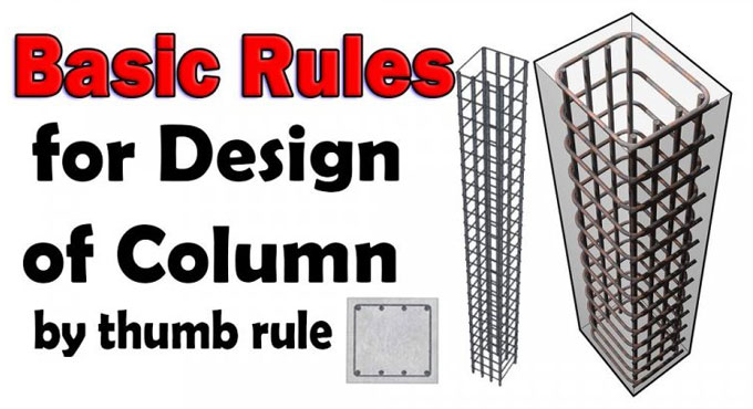
Columns are essential support structures that are almost inevitably used in any construction projects. From ancient times, columns have been an indispensable part of erecting buildings, them being one of the most important load-bearing members. Obviously, one needs to be careful while designing such important structures.
As per the construction sciences and technologies, there are many rules applicable to specific columnar structures. However, there are some few basic rules of column designing that all engineers can keep in mind while designing most types of columns and similar vertical supports.
Today, we will discuss these important thumb rules of column design in this article. Needless to say, columns need to be designed keeping in mind the total amount of forces acting on the structure. But also, keeping these basic guidelines in mind can prevent architects and engineers from making silly mistakes.
Rule 1: Essentially, the size of the columns would depend upon the total amount of forces acting on the column. In short you can consider this as the total load on a column. This will make or break the column, so you need to be ensuring that your columns design can withhold this entire load and anything else that may come later.
That is, the total load on a column may be not only the weight of the structure that it bears, but also the movable materials that structure will bear. For example, while designing a multi-storied godown, you will need to care about not only the weight of the floor and the walls and the roof, but more also, the weight of the goods that are going to be stored on that floor. This can get pretty great in case of solid materials.
Thumb Rules to Follow While Designing Columns
~~~~~~~~~~~~~~~~~~~~~~~~~~
Published By
Rajib Dey
www.constructioncost.co
~~~~~~~~~~~~~~~~~~~~~~~~~~

Wednesday, June 19, 2019

ACI 318-14 approved design guidelines of isolated footing

Isolated alias single footing is utilized to provide support to single RCC columns. It is cost-effective and suitable when the columns are placed at comparatively long distances, loads operating on footings are less and the safe bearing strength of the soil usually remains high.

Isolated footing is categorized as pad footing and sloped footing.

The isolated footing is arranged underneath the column to disperse the loads securely to the bed soil.

The design of isolated footing is made for the following purposes :-

Area of footing

Thickness of footing

Reinforcement details of footing with a satisfactory moment and shear force review.
The design of isolated footing is made on the basis of the guidelines set by ACI 318-14.

1. The compressive strength of concrete should satisfy the needs for both strength and stability. As per ACI 318-14, least concrete compressive strength should be 17MPa for normal applications.

2. With adherence to ACI 314-14 section 20.2.1.1, the deformed type steel bars should be used.

3. Factored forces and moments provided at the base of columns are transmitted to the foundation with reinforcement, dowels, anchor bolts, or mechanical connectors.

4. There should be least reinforcement even if the concrete bearing strength is not crossed.

5. Adequate anchorage should be arranged for tension reinforcement if reinforcement stress is not directly relative to the moment like in sloped, stepped or tapered foundation.

6. There should be sufficient anchorage length of both flexural and dowel reinforcement to get rid of bond failure of the dowels in the footing and to resist failure of the lap splices among the dowels and the column bars.

7. As per ACI 318-14 section 13.3, depth of footing over reinforcement should not remain under 150 mm.

8. The depth of the footing should be in such a manner that the shear strength of the concrete remains equivalent or surpasses the critical shear forces (one-way shear and punching shear) developed with factored loads.

9. In sloped, stepped, or tapered foundation, location and depth steps and angle of slope should satisfy design requirements at each section.

10. Concrete cover of 75 mm is necessary when the concrete is cast against soil.

11. With adherence to ACI Code specifications, base area of footing is set from unfactored forces and moments transferred by footing to soil and the permissible soil pressure evaluated through principles of soil mechanics. To get the necessary base area of the footing, the column service loads are divided with permissible net soil pressure of the soil. The net factored soil pressure is equivalent to factored load column loads by the selected footing area.

Read more

ACI 318-14 approved design guidelines of isolated footing

~~~~~~~~~~~~~~~~~~~~~~~~
Published By
Rajib Dey
www.constructioncost.co
~~~~~~~~~~~~~~~~~~~~~~~~

Monday, June 10, 2019

Details of stress-strain curve in steel bars

The objective of stress-strain curve is to define the behavior of steel bars under loads. To develop the curve, the steel specimens are examined. A steel specimen is progressively drawn through a testing machine unless it breaks, and then stress and respective strains are recorded. The stresses are then outlined along the vertical axis, and because of these stresses, respective strains are outlined along the horizontal axis.

Several mark points exist on the stress-strain curve which demonstrate different stages for steel specimen to move through before occurrence of fracture. It is very important to recognize the stress-strain curve for getting the ability to understand the response of steel bars when exposed to loads.

When the steel specimen is exposed to load, it functions like an elastic material to indicate that the stresses and strains are proportional. When the load is raised, the specimen begins to lose its proportionality and ultimately collapses or yields. When the load is raised beyond the yield point, the steel bar undergoes stress hardening and gets the strength to resist larger stress, after it attains the fracture point.

Stress-strain Curve of Steel Bars: When the steel specimen is exposed to load, it passes through different stages ranging from elastic stage, yield point, and fracture.

Limit of Proportionality: This stage is demonstrated on the stress-strain curve from the initial point until point “A”. In this region, the stress remains low and fails to produce permanent strain. The stress and strain are relative to each other, as a result when the stress is eliminated, the steel bar would recapture its original shape.

Elastic Limit: It is situated among point “A” and “B” on the curve. When the stress on steel specimen is again raised, it will produce elastic strain. The stress and strain are not relative to each other.

Yield Point: It is the most vital point on the stress-strain curve from the design perspective. This point is indicated by letter B on the curve and treated as the failure point in the design of reinforced concrete structure. Therefore, when the steel bar attains the yield point in the reinforced concrete element, it will be treated as a failed member.

The yield point is the origin of steel plastic deformation. The stress and strain are not relative. The point B is defined as the upper yield point while the point C is the lower yield point.

Ultimate Strength: When the stress is again raised beyond yield point, strain hardening occurs that is demonstrated from point C to D, beyond which necking commences. Throughout strain hardening, the material is subjected to changes in its atomic and crystalline structure that leads to greater resistance of the material to further deformation. The maximum ordinate in the stress-strain diagram i.e. point D belongs to the ultimate strength or tensile strength.

Rupture Strength: Rupture strength stands for the strength of the material at rupture. It is also called the breaking strength. It refers to the point “E” on the stress-strain diagram.

Read more

Details of stress-strain curve in steel bars
~~~~~~~~~~~~~~~~~~~~~~~~
Published By
Rajib Dey
www.constructioncost.co
~~~~~~~~~~~~~~~~~~~~~~~~

Monday, March 4, 2019

Types of steel bars for construction

Generally, the following four types of steel bars are utilized in concrete structure : Types of Steel Reinforcement used in Concrete Structures -
1. Hot Rolled Deformed Bars: It is extensively used in regular RCC structures. Hot rolling is performed in the mills by providing deformations on the surface i.e. ribs with the purpose of developing bond with concrete.
The stress - strain curve presents a separate yield point accompanied with a plastic stage in which strain is raised without raising the stress. It is succeeded by a strain hardening stage. It comprises of typical tensile yield strength of 60,000 psi.
2. Mild Steel Plain bars: These belong to plain bars and do not contain ribs on them. These are suitable for small projects where cost is a vital factor. Since the plain bars can’t be secured properly with concrete therefore hooks are arranged at the ends. In this type of steel, stress - strain curve also presents a separate yield point accompanied with a plastic stage in which strain is raised without raising the stress. It is succeeded by a strain hardening stage. Normal tensile yield strength is 40,000 psi.
3. Cold Worked Steel Reinforcement: Cold worked reinforcement is provided if hot rolled steel bar encounters process of cold working. Cold working is done by twisting or drawing the bars at room temperature. It properly reduces the Plastic Stage in the Stress-Strain curve, even though it provides more control on the size and tolerances of bars. As there is no plastic stage, ductility becomes lower as compared to Hot Rolled bars. It is mostly effective for the projects where low tolerances and straightness are vital factors.
The stress – strain curve does not present a separate yield point since the plastic stage is completely discarded. Yield point is obtained by drawing a line parallel to the Tangent Modulus at 0.2% strain. Yield stress stands for the point where this line overlaps the stress – strain curve.
It is defined as 0.2% proof stress. If yield stress is obtained at 0.1% strain it is defined as 0.1% proof stress. Normal tensile yield strength is 60,000 psi.
4. Prestressing Steel: Prestressing steel is applied in the form of bars or tendons which are constructed with several strands. The application of tendons / strands is very common since these can be easily placed in different profiles. Prestressing strands are built up with various wires (usually with 2, 3 or 7 wire strands). Normal seven wire strand comprises of six wires spun around the seventh wire with marginally a greater diameter, consequently a helical strand is created.
These wires are cold drawn and contain very high tensile ultimate strength (normally 250,000 - 270,000 psi). Due to extreme tensile strength, the concrete is prestressed properly even after experiencing short term and long term losses. These are applied as prestressed concrete in bridges or prestressed slabs in buildings. Prestressing steel also comes as non-bonded strands encased in PVC sheath. It is applied in Post-Tensioning of members. Prestressing strands can also be applied as Low Relaxation Strands which show low relaxation losses after prestressing. These are normally applied in prestressing members with large distances./p>
Because of cold drawing method, plastic stage in this type of steel is removed. Thus stress – strain curve does not present a separate yield point. Yield point is obtained at 0.1% or 0.2% proof stress. The design of prestressed concrete is not based on yield stress rather it relies on the ultimate strength; therefore the property of interest in this type of steel is the ultimate strength.
Types of steel bars for construction

~~~~~~~~~~~~~~~~~~~~~~~~~~
Published By
Rajib Dey
www.constructioncost.co
~~~~~~~~~~~~~~~~~~~~~~~~~~