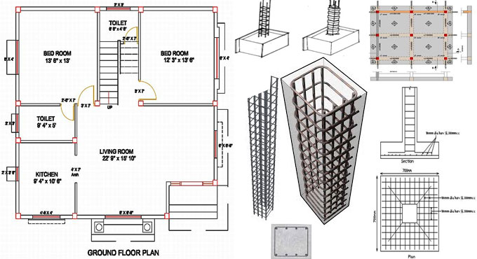
RCC or reinforced concrete structures comprise of various building elements like Footings, Columns, Beams, Slabs, Staircase etc.
These elements are reinforced with steel to increase the strength of the structure. Staircase is considered as one such vital element in a RCC structure.
Given below, the details on several types of staircases and how the design is created for the dog-legged reinforced cement concrete staircase.
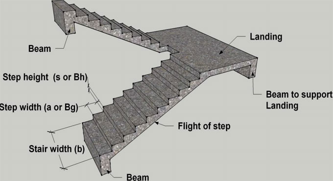
Stairs: There are lots of steps in a stair which are organized in a series to provide entry to various floors of a building. As a stair is the only medium for making communication among different floors of a building, the position of the stair should be perfect.
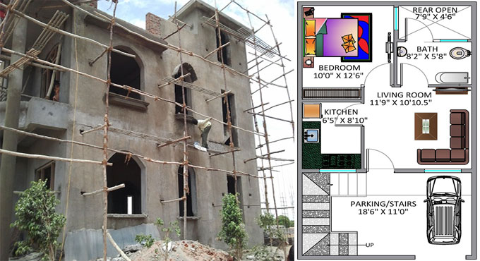
In a residential building, the staircase should remain adjacent to the main entrance.
In a public building, the stairs should be constructed from the main entrance itself and situated centrally, to give rapid entry to the main apartments.
There should be adequate lighting and suitable ventilation for all staircases.
Different types of Staircases - a. Straight stairs, b. Dog-legged stairs, c. Open newel stair and d. Geometrical stair
RCC Dog-legged Staircase design: In this type of staircase, the subsequent flights mount in opposite directions. The two flights in plan are not detached with a well. A landing is arranged in accordance with the level at which the direction of the flight varies.
Method for Dog-legged Staircase design: Depending on the direction along which a stair slab extents, the stairs are categorized into the following two types.
1. Stairs extending to the horizontal direction
2. Stairs extending to the vertical direction