adsense analytic

Showing posts with label #water cement ratio. Show all posts

Thursday, September 3, 2020

Details guidelines on RCC Staircase Design

 RCC or reinforced concrete structures comprise of various building elements like Footings, Columns, Beams, Slabs, Staircase etc.

These elements are reinforced with steel to increase the strength of the structure. Staircase is considered as one such vital element in a RCC structure.

Given below, the details on several types of staircases and how the design is created for the dog-legged reinforced cement concrete staircase.

Stairs: There are lots of steps in a stair which are organized in a series to provide entry to various floors of a building. As a stair is the only medium for making communication among different floors of a building, the position of the stair should be perfect.

In a residential building, the staircase should remain adjacent to the main entrance.

In a public building, the stairs should be constructed from the main entrance itself and situated centrally, to give rapid entry to the main apartments.

There should be adequate lighting and suitable ventilation for all staircases.

Different types of Staircases - a. Straight stairs, b. Dog-legged stairs, c. Open newel stair and d. Geometrical stair

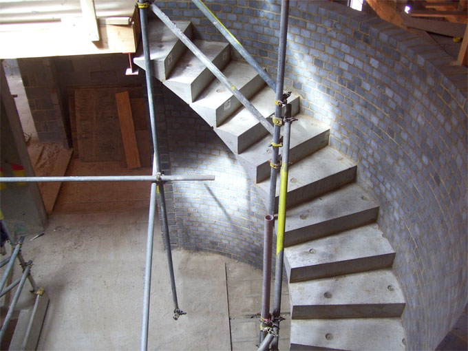
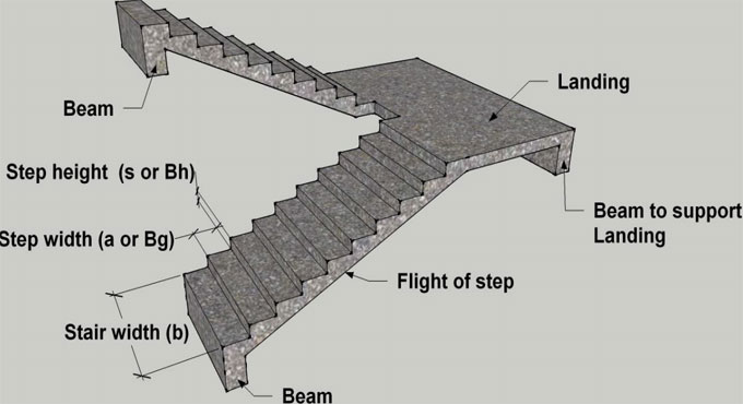
RCC Dog-legged Staircase design: In this type of staircase, the subsequent flights mount in opposite directions. The two flights in plan are not detached with a well. A landing is arranged in accordance with the level at which the direction of the flight varies.

Method for Dog-legged Staircase design: Depending on the direction along which a stair slab extents, the stairs are categorized into the following two types.

1. Stairs extending to the horizontal direction
2. Stairs extending to the vertical direction
Details guidelines on RCC Staircase Design

~~~~~~~~~~~~~~~~~~~~~~~~
Published By
Rajib Dey
www.constructioncost.co
~~~~~~~~~~~~~~~~~~~~~~~~

Tuesday, September 1, 2020

Some important thumb rules for making the layout of any Column

 Guidelines to be followed for making A column layout is created on the basis of the following directions :-

The design of columns should be made with regard to the total forces operating on the structure. In order to avoid errors, there are some important thumb rules which should be followed by every Civil engineer and Architect.

The following three thumb rules should be followed:

1. Size of the Columns
2. Spaces among Columns
3. Alignment of columns

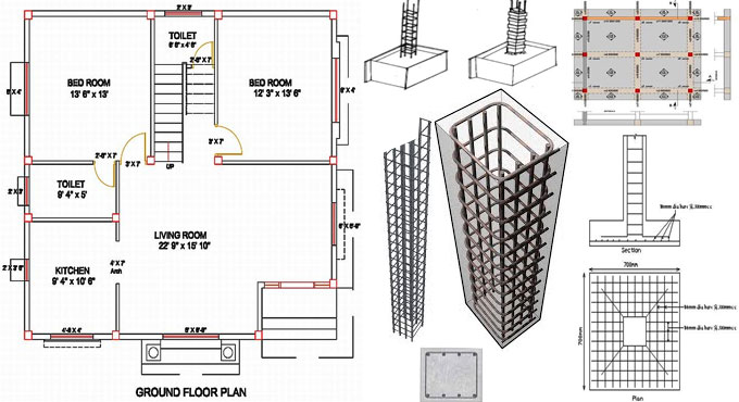
Minimum Size of RCC columns: The size of the columns is based on the total loads operating on the columns which range from axial loads and lateral loads. Large beam spans cause bending moment in the beams as well as in columns which are drawn by the stresses in the beams.

To apply this general thumb rule, presume a structure of G+1 floors high, with standard 6? walls. Least size of an RCC column should not be under 9? x 12? (225mm x 300mm) with 4 bars of 12 MM Fe415 Steel.

The dimension of the column should be 9? x 12? (225 mm x 300mm) with 6 bars of 12 MM Fe500 steel. It is recommended to utilize M20 grade concrete for the structure (ratio 1 part Cement : 1.5 parts Sand : 3 parts Aggregate with 0.5 parts water by volume). It is also suggested to utilize 8 MM stirrups at a span of 150 MM center to center all through the length of column.

This setup of 9? x 12? RCC columns is secured for G+1 Floors.

Spaces (distance) among two columns: To install the above column, a distance of up to 5 meters should be maintained. It is suggested to apply beams of size 9? X 12? (225 MM x 300MM) having a slab thickness of 5? (125 MM) cast in M20 concrete for spans up to 5m. Some other factors like secondary and tertiary spans, point loads and wall loads which should also be taken into consideration. The thumb rules can be useful when the structure is simple.

Some important thumb rules for making the layout of any Column

~~~~~~~~~~~~~~~~~~~~~~~~
Published By
Rajib Dey
www.constructioncost.co
~~~~~~~~~~~~~~~~~~~~~~~~

Friday, August 28, 2020

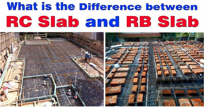
Basic differences among RC slab and RB slab

 RC Slab: RC Slab stands for a horizontal structural component of steel reinforced concrete. Generally, the thickness of RC slab varies from 100mm to 500mm. RC Slabs are frequently applied as floorings, ceilings etc. Slabs are supported on two sides only or contain beams on all four sides.

RC slabs are erected with formwork, that is generally created with wooden planks, boards, plastic & steel. In recent times, prefabricated RC slabs are also utilized. RC Slab is also termed as Reinforced Concrete Slab that arranges reinforcement for retaining the strength of the structure. Straight bar and alternative cranked bars are also applied as reinforcement in the RC slabs.

RB slabs: RB slab stands for a reinforced brick slab that is suitable for floorings and ceilings. RB slab is erected with steel reinforcement arranging spacing with the bricks. The construction cost of RB slab is less with regard to RC slab.

An RC slab alias Reinforced Cement slab is found in buildings and in bridge construction. The reinforcement is provided with steel bars which are arranged with some distances according to design and based on the load the slab has to undergo.

An RB slab alias Reinforced Brick slab is ideal for roofs in buildings. It is less costly as compared to RC slabs. The reinforcement is provided with steel bars which are arranged with some distances according to design and based on the load the slab has to undergo.

The distance among the bars is occupied by bricks which are arranged on its edge. The depth of the slab remains 4.5 in. The bars are provided among the bricks in both directions. The cement-sand mortar along with least possible water quantity is used to fill up the distance among the bars.

Basic differences among RC slab and RB slab

~~~~~~~~~~~~~~~~~~~~~~~~
Published By
Rajib Dey
www.constructioncost.co
~~~~~~~~~~~~~~~~~~~~~~~~

Thursday, August 27, 2020

The role of Site Engineer & Project Engineer in a construction project

 Site engineers and project engineers frequently work in tandem on a job performing various things. Both play important role for major projects with equally significant liabilities.

Comparing Site Engineers to Project Engineers: Both the site engineers and project engineers take diverse liabilities for accomplishment for different types of construction projects.

Site engineers have sound technical skills which can be applied for specific engineering aspects of the project. Project engineers supervise the general operation of the project. They acquire the resource orders, deal with clients, and coordinate with designers and other engineers.

Given below, the basis differences among site engineers and project engineers :-

Liabilities of Site Engineers vs. Project Engineers

Site engineers perform according to a designer's plans, engineer's specifications and city codes to execute their jobs. Conversely, the project engineers perform very intimately with management and planners in an consultative manner to produce blueprints that fulfill the objectives of the clients as well as city and state codes.

Site Engineers: The site engineers may possess an office somewhere, but in several occasions they are active at the job site ensuring specific jobs are accomplished perfectly and with adherence to code.

These engineers examine that a building's wiring is completed properly, the plumbing will not leak, or the walls will not fall. They also have to rationalize modifications to orders, redrawing alternate plans and settling technical problems instantly and within the budget.

Given below, the liabilities of a site engineer:

The role of Site Engineer & Project Engineer in a construction project

~~~~~~~~~~~~~~~~~~~~~~~~
Published By
Rajib Dey
www.constructioncost.co
~~~~~~~~~~~~~~~~~~~~~~~~

Tuesday, August 25, 2020

Details guidelines on RCC Staircase Design

 RCC or reinforced concrete structures comprise of various building elements like Footings, Columns, Beams, Slabs, Staircase etc.

These elements are reinforced with steel to increase the strength of the structure. Staircase is considered as one such vital element in a RCC structure.

Given below, the details on several types of staircases and how the design is created for the dog-legged reinforced cement concrete staircase.

Stairs: There are lots of steps in a stair which are organized in a series to provide entry to various floors of a building. As a stair is the only medium for making communication among different floors of a building, the position of the stair should be perfect.

In a residential building, the staircase should remain adjacent to the main entrance.

In a public building, the stairs should be constructed from the main entrance itself and situated centrally, to give rapid entry to the main apartments.

There should be adequate lighting and suitable ventilation for all staircases.

Different types of Staircases - a. Straight stairs, b. Dog-legged stairs, c. Open newel stair and d. Geometrical stair.

RCC Dog-legged Staircase design: In this type of staircase, the subsequent flights mount in opposite directions. The two flights in plan are not detached with a well. A landing is arranged in accordance with the level at which the direction of the flight varies.

Method for Dog-legged Staircase design: Depending on the direction along which a stair slab extents, the stairs are categorized into the following two types.

Details guidelines on RCC Staircase Design

~~~~~~~~~~~~~~~~~~~~~~~~
Published By
Rajib Dey
www.constructioncost.co
~~~~~~~~~~~~~~~~~~~~~~~~

Monday, August 24, 2020

Types, applications and benefits of aggregates

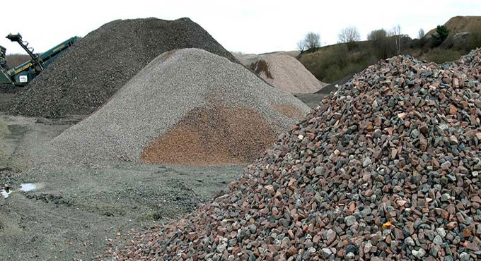
 Aggregates are the vital components in concrete. They are granular materials obtained from the natural rocks, crushed stones as well as natural gravels and sands. The aggregates are amalgamated with a binding material in fixed ratios to form concrete.

Aggregates normally capture about 70% to 80% of the concrete volume and they significantly affect the different properties like strength, hardness and stability of the concrete. Aggregates function as fillers or volume increasing components.

Applications of aggregates:

1. They are used as an underlying material for foundations and pavements.

2. They are used as constituents in portland cement concrete & asphalt concrete.

Properties of Aggregate: Aggregate should contain the properties given below -

1. It should be chemically static that means they should not respond to cement or any other aggregate or admixture.

2. It should contain adequate hardness to avoid scratching and erosion in the hardened state.

3. It should contain adequate toughness to sustain impact and vibratory loads.

4. It should be physically strong to carry compressive and normal tensile loads in ordinary mixture.

5. It should not contain impurities, inorganic or organic in nature for which the quality of concrete will be affected significantly.

6. It should have capabilities to produce usable plastic mixture after getting mixed with cement and water.

Types, applications and benefits of aggregates

~~~~~~~~~~~~~~~~~~~~~~~~
Published By
Rajib Dey
www.constructioncost.co
~~~~~~~~~~~~~~~~~~~~~~~~

Saturday, August 22, 2020

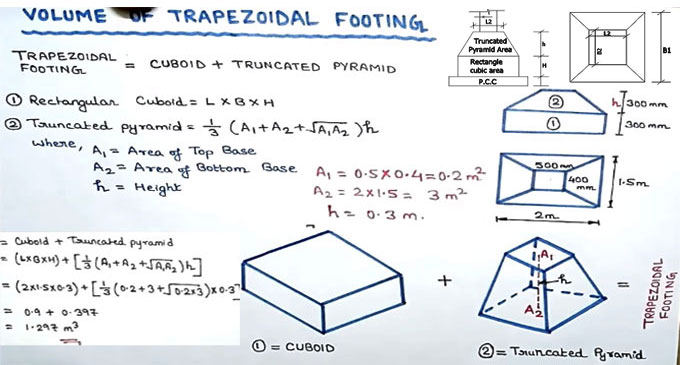
Step-by-step guidelines to calculate the volume of a trapezoidal footing

 Isolated footings alias pad or spread footings are mostly found in shallow foundations with the intention of conveying and distribution of concentrated loads resulting from columns or pillars. Isolated footings either comprise of reinforced or non-reinforced material. For the non-reinforced footing, the height of the footing should be larger to maintain the required spreading of load.

To apply Isolated footings, there should not be fluctuating settlements under the whole building.

Necessity of materials for Isolated Footing : The following materials will be utilized for building up a isolated footing - Shutter Material, MS Rod, Binding Wire, Cover Block and Chair, Concrete.

Shutter Material for Isolated Footing: In isolated footing, generally wooden shutter materials are utilized. Often, steel shutter materials can also be applied.

This type of footing is utilized under the following conditions : Columns are not arranged narrowly. Fewer loads enforce on footings. The safe bearing strength of the soil is usually extreme.

In this construction video tutorial, one will learn how to make calculation for finding out the volume of Trapezoidal Footing at construction site.

Trapezoidal footing is formed by combining cuboid & truncated pyramid. Cuboid may be rectangular or square in shape. A special case of footings is the trapezoidal footing that may be utilized to bear two columns of unbalanced loads when distance outside the column of the massive load is restricted.

A trapezoidal footing is applied in such a manner that the center of gravity of the footing is located under the outcome of the loads. In that order, the distribution of contact pressure will be consistent.

Step-by-step guidelines to calculate the volume of a trapezoidal footing

~~~~~~~~~~~~~~~~~~~~~~~~
Published By
Rajib Dey
www.constructioncost.co
~~~~~~~~~~~~~~~~~~~~~~~~

Friday, August 21, 2020

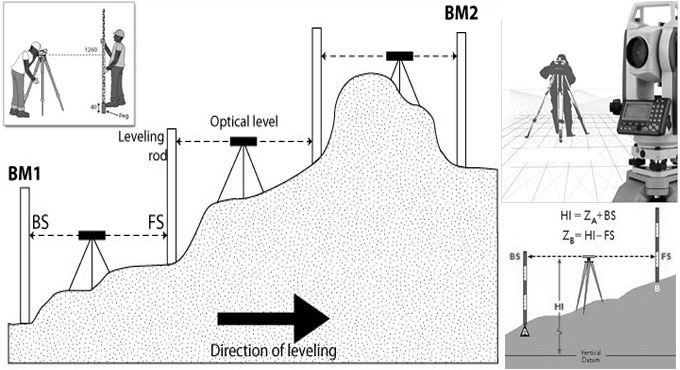
Types of Leveling Methods in Surveying

 Leveling is the most generally utilized technique for getting the elevations of ground points comparative with a reference datum and is normally done as a different system to those utilized in fixing planimetric position. The fundamental idea of leveling includes the estimation of vertical separation comparative with a horizontal line of sight. Consequently, it requires a graduated staff for the vertical estimations and an instrument that gives a horizontal line of sight.

The different types of Leveling in ground survey are:

a. Precise or Geodetic Leveling
b. Ordinary or Simple Leveling

Techniques for Leveling

Techniques for leveling might be immediate, for example:

1. Simple Leveling
2. Differential Leveling
3. Profile Leveling
4. Cross Sectioning

5. Reciprocal Leveling
6. Precise leveling
7. Check Leveling
8. Fly Leveling

Or then again might be aberrant, e.g.

1. Trigonometric Leveling
2. Barometric Leveling
3. Hypsometry

Types of Leveling Methods in Surveying

~~~~~~~~~~~~~~~~~~~~~~~~
Published By
Rajib Dey
www.constructioncost.co
~~~~~~~~~~~~~~~~~~~~~~~~

Thursday, August 20, 2020

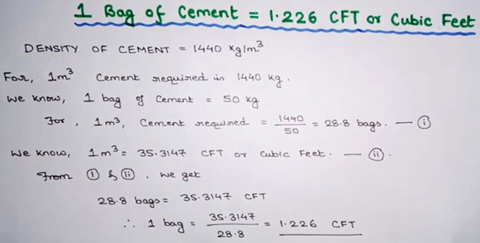
How to estimate cement bags in 1 cubic meter

 Suppose the proportion of nominal mix is 1:2:4 (one part cement, 2 part sand and 4 part aggregate)

Wastage of cement is taken as 2%
Output of mix is provided as 67%.

For 1 cum output, the requirement of dry mix is 1/0.67 = 1.49 say 1.50 cum.
After including the wastage (2%), the output will be (1.50 + 0.02) = 1.52 cum.
Volume of cement = (cement/cement+sand+aggregate) × Total material

= (1/1+2+4) × 1.52
=0.2171 cum
The density of cement is 1440 kg/cum and
Weight of 1 bag cement = 50 kg.

So, volume of 1 bag cement = 50/1440
=0.0347 cum.
No. of cement bags essential in 1 cubic meter = 0.2171/0.0347
= 6.25 bags.
The above formula can be utilized for measuring cement for other nominal mixes.

To get more details, watch the following video tutorial.

How to estimate cement bags in 1 cubic meter

~~~~~~~~~~~~~~~~~~~~~~~~
Published By
Rajib Dey
www.constructioncost.co
~~~~~~~~~~~~~~~~~~~~~~~~

Wednesday, August 19, 2020

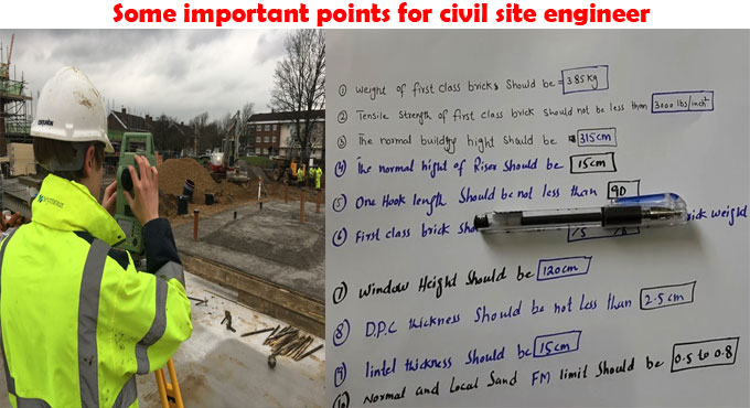
Some important points for civil site engineer

 Civil engineer accomplishes several tasks at construction site. Given below, some points, tips and tricks essential for a civil engineer for doing rapid calculations and providing instant solutions to construction site problems.

Given below, some general points which civil site engineers should focus on to simplify the construction work whereas retaining the quality of construction.

Lapping should not be provided for the bars with diameters in excess of 36 mm.

Highest spacing for chair should be 1.00 m (or) 1 No per 1m2.
For dowels rod, lowest 12 mm diameter should be applied.

For Chairs, bars with minimum diameter of 12 mm should be utilized.
Longitudinal reinforcement should remain not below 0.8% and in excess of 6% of gross C/S.
Least bars for square column is 4 No’s and 6 No’s for circular column.
Main bars in the slabs should not be under 8 mm (HYSD) or 10 mm (Plain bars) and the distributors should not be under 8 mm and not in excess of 1/8 of slab thickness.

Least thickness of slab should be 125 mm.
Dimension tolerance for cubes should be + 2 mm.
Free fall of concrete is permissible maximum to 1.50m.
Lap slices should not be applied for bar greater than 36 mm.
Water absorption of bricks should not be in excess of 15 %.
PH value of the water should not be under 6.

Some important points for civil site engineer

~~~~~~~~~~~~~~~~~~~~~~~~
Published By
Rajib Dey
www.constructioncost.co
~~~~~~~~~~~~~~~~~~~~~~~~

Tuesday, August 18, 2020

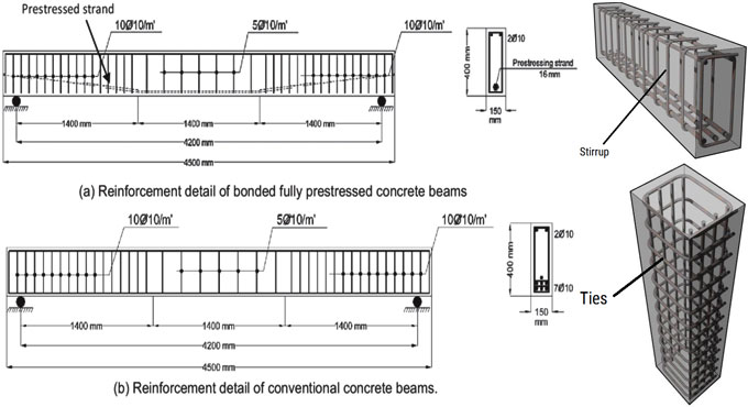
Stirrups in a Concrete Beam

 As engineers, we plan fortified concrete members and frequently we are approached to watch the steel reinforcement in field before the concrete is set. We must ensure the concrete establishments, beams, segments, and so forth are fabricated the manner in which they were structured. During our perceptions we regularly find that steel beam stirrups, utilized in fortified concrete plan, are not introduced accurately and it isn't in every case clear to the installer why they are significant.

Truly, beam stirrups had been utilized sparingly in private development. In any case, as of late concrete beam sizes have gotten shallower and ranges have expanded. We would say, this has been the aftereffect of structural plan and building tenant prerequisites. The expanded expense of establishment components, for example, bored docks, has additionally been a factor. Expanding concrete beam ranges, to lessen the requirement for extra wharfs, has brought about the requirement for the utilization of steel stirrups.

Usage of Stirrups

Concrete beams shift inside and out. The more profound the beam, the more shear limit. At the point when the profundity isn't satisfactory, steel stirrups must be added to expand the shear limit of the beam. These stirrups are normally one bit of steel that is twisted into a rectangular shape. Regularly little distance across steel is utilized, for example, #3 and #4 rebar. The stirrup normally folds over the base and top bars of the beams.

A planner ought to determine the size, dispersing and area along the length of the beam where the stirrups are required. We like to indicate the stirrup measurements in our areas, with the goal that the stirrup can be made before establishment. Stirrups will be required at zones of high shear, for example, bearing focuses and beneath huge point loads.

The installer ought to be mindful so as to manufacture the stirrup from one bit of steel and sufficiently cover each end (contact the Structural Engineer or allude to the ACI code for varieties). Again and again, the stirrup isn't pre-manufactured and the installer attempts make the stirrup in the field, after the flat bars are as of now set up.

This is normally self-evident, in light of the fact that the stirrup is built from two pieces with insufficient lap join. It is a lot simpler and effective to introduce a stirrup simultaneously the even reinforcement is being introduced. Continuously contact the Structural Engineer with any inquiries concerning size, shape, separating and establishment of stirrups preceding assessment. This will help forestall a minute ago changes, while the concrete truck is pausing.

Stirrups are closed circle bars tied at normal stretches in beam reinforcement to hold the bars in position. Sidelong ties are utilized to hold the situation of the reinforcement in a segment without upsetting the concrete space.

Stirrups in a Concrete Beam

~~~~~~~~~~~~~~~~~~~~~~~~
Published By
Rajib Dey
www.constructioncost.co
~~~~~~~~~~~~~~~~~~~~~~~~

Monday, August 17, 2020

Some useful tips to work out the length of the bent bars

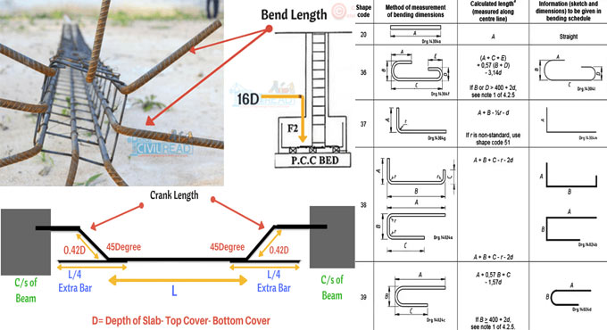
 While fabricating reinforcing bars with bends, the straight bar is primarily cut to a length that is under the sum of the specified dimensions of the bent bar.

The variation among the detailed length and the cut length belongs to the “bend curvature deduction” and called as various names like gain, creep, and gyp. Usually, the fabricators and programmers get the bend curvature deduction from a bend deduction table.

In the following table 1, the deductions for 45- and 90-degree bends of common bar sizes are provided.

Figure 1 illustrates a No. 8 (No. 25) bar with a standard hook and sides estimating 1 ft 4 in. and 4 ft (400 and 1220 mm). The detailed length of this bar is obtained by summing up the two sides, or 5 ft 4 in. (1620 mm). From Table 1, the deduction for a 90-degree bend on a No. 8 (No. 25) bar is 2-1/2 in. (65 mm). So, in such a case, the cut length of the bar should be 5 ft 1-1/2 in. (1555 mm).

The usual standard for working out the cut length of a bar is along the actual centerline of the bar, that is equivalent to the neutral axis of the bar cross section before bending. The cut length of a bent bar is less than the sum of the finished dimensions due to the following reasons :-

with a easy-to-follow mathematical calculation.

If the exterior fibers of the bar are elongated easily, the inner fibers of the bar are constrained by friction against the bending mandrel, so, the neutral axis shifts inward approaching the mandrel. It is critical to measure this component. The inconsistency arises from computing the lengths on the basis of the actual centerline is not very important.

Some useful tips to work out the length of the bent bars

~~~~~~~~~~~~~~~~~~~~~~~~
Published By
Rajib Dey
www.constructioncost.co
~~~~~~~~~~~~~~~~~~~~~~~~

Thursday, August 13, 2020

Some useful tips to measure loads on column, beam and slab

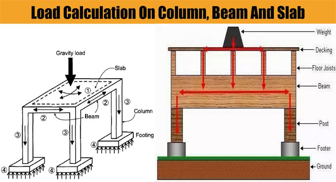
 In order to work out the total load on columns, Beam and Slab, there should be clear ideas on the types of loads enforcing on the column.

Different Loads operating on Column:

1) Column Self Weight X Number of floors
2) Beams Self Weight per running meter
3) Load of walls per running meter
4) Total load on Slab (Dead load + Live load + Self weight)

Apart from above loading, the columns are also susceptible to bending moments which should be taken into consideration in the final design.

For Colomn: The Self weight of Concrete remains approx 2400 kg/m3, that is similar to 240 kN and self weight of steel is approx 8000 kg/m3.

Therefore, if we consider a column size of 230 mm x 600 mm with 1% steel and 3 meters standard height, the self weight of column is approx 1000 kg per floor that is equivalent to 10 kN.

At the time of making calculation, self weight of columns is taken as 10 to 15 kN per floor.

For Beam: Similar method is also used for making calculations of beam. Suppose, each meter of beam contains dimensions of 230 mm x 450 mm without slab thickness. Therefore, the self weight should be approx 2.5 kN per running meter.

For Walls: The Density of bricks differs among 1500 to 2000 kg per cubic meter. For a brick wall with thickness 6 inch, height 3 meter a length 1 meter. The load / running meter should be equivalent to 0.150 x 1 x 3 x 2000 = 900 kg, that is identical to 9 kN/meter. This method is useful for working out the load of brick per running meter for any brick type.

Some useful tips to measure loads on column, beam and slab

~~~~~~~~~~~~~~~~~~~~~~~~~~
Published By
Rajib Dey
www.constructioncost.co
~~~~~~~~~~~~~~~~~~~~~~~~~~

Wednesday, August 12, 2020

How to Test the Consistency of Cement

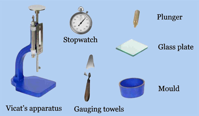
 Definition: The standard consistency of cement paste is the level of water required, where the plunger infiltrates into the cement paste of about 5mm to 7mm from the base of the shape and in the other word consistency of cement is the base measure of water required to start a synthetic response among water and cement to frame a paste.

A Minimum quantity of water required to initiate the chemical reaction between water and cement to form a paste is known as consistency of cement. The cement consistency which will allow the Vicat plunger to penetrate to 5-7 mm point from the bottom of Vicat mould is known as standard consistency. For reference purposes, the standard consistency of a Portland cement fluctuates between 25–35%.

Significance: We as a whole realize that the strength of concrete relies upon the quality Cement. To get the necessary cement strength, we need to include the perfect measure of water. Water underneath standard security won't start the concoction response among water and cement, which will build the strength of cement.

Water less than the standard consistency would not initiate the chemical reaction between water and cement resulting in the strength of cement. Water more than the consistency results in excess water and strength reduction. That’s why it is important to know the standard consistency of cement material. On the other hand, overabundance of water over steadiness brings about abundance moisture and loss of strength. In this manner it is essential to know the standard consistency of cement.

Different tests on cement:

1. Fineness test of Cement by dry sieving method with 90 micron strainer
2. Adequacy test of cement by Le Chatelier

Reasons for the Test: We know that the cement we used on our site is mostly affected by the following

1. Weather Conditions.
2. Excessive combination of Silica. One of the cement ingredients which determines the initial and final setting time of cement paste.
3. The fineness of cement.
4. Manufacturing Defects.

By Standardising the consistency of cement, we know how much water is required to produce an effective cement which will eventually produce good quality concrete. Standard Consistency of an ordinary Portland cement varies between 25-35%. That means we need 25% of water in volume to make a standard consistency of cement.

For Example, If we need to calculate the amount of water required for a 200 g of cement which has 30% consistency means then we need 200*30% = 60g water to prepare a standard consistency. This is what we are going to find in this test.

How to Test the Consistency of Cement

~~~~~~~~~~~~~~~~~~~~~~~~~~
Published By
Rajib Dey
www.constructioncost.co
~~~~~~~~~~~~~~~~~~~~~~~~~~

Monday, August 10, 2020

Types of Pointing in Brick Masonry Construction

 Pointing is the craft of consummation the issue joints inside the uncovered brick work with a satisfactory cement or lime mortar, to shield the joints from climate impacts, to upgrade the presence of building structure. The joints on the essence of any stone work are generally filled, though the divider is being raised.

Pointing is finished with the accompanying mortar blends:

1. Lime mortar 1: 2 blend (1 lime: 2 sand)
2. Cement mortar 1: 3 blend (1 cement: 3 sand)

Technique for Pointing: All the mortar joints in the brick work are raked out to a profundity of 10-15mm with the assistance of pointings tool. Residue and free mortar are completely cleaned. The joints and the surface are washed with clean water and saved wet for at times.

The mortar is taken in a little dish and the old mortar is squeezed into the joints and loaded up with little trowels to reach the joints. Joints are disposed of flushed, sunk, or raised relying upon necessities, expelling overabundance mortar. The completed work is restored for 3-4 days in instances of lime mortar and for 10 days when cement mortar is utilized.

Types of Pointing: Pointing is characterized by wrapping up. The kind of pointings is choice dependent on the sort of brick work, the idea of the structure and the ideal impact of finish.

Beaded pointing: This kind of pointings gives a generally excellent appearance however is hard to keep up. The raked joints are loaded up with a mortar and completed flush with the essence of the property after which are beaded by a steel thruway with a sunken edge in the middle of the joints.

Flush pointing: In any pointings, joints are raked and they are finished flush with the essence of the block workmanship. The sides are accurately cut. It is the most effortless kind of pointings, which is broadly utilized in brick work. This pointing doesn't give a great look, however it is very strong and it doesn't empower dust, earth to hold up over it.

Recessed pointing: In this sort of pointings, the mortar is kept vertical however inside the outside of the divider with the assistance of reasonable hardware. This sort of pointings is reasonable to withstand crafted by blocks of better surface and better quality mortar.

Rubbed or grooved pointings: In this sort of pointings, the raked joints are topped off flush with face or the moan and crescent indents are framed by an uncommon tool. This kind of pointings is regularly utilized, it improves the appearance of the cry.

Types of Pointing in Brick Masonry Construction

~~~~~~~~~~~~~~~~~~~~~~~~~~
Published By
Rajib Dey
www.constructioncost.co
~~~~~~~~~~~~~~~~~~~~~~~~~~

Wednesday, May 29, 2019

Calculation of water cement ratio in concrete

Definition Of Water Cement Ratio - Water Cement Ratio indicates the ratio among the weight of water to the weight of cement applied in concrete mix.
Generally water cement ratio remains under 0.4 to 0.6 according to IS Code 10262 (2009) for nominal mix (M10, M15 …. M25).
The strength of concrete is directly influenced by water cement ratio. When, the water cement ratio is perfect, the strength of concrete is raised otherwise the strength will be reduced.
Role of Water in Concrete: Concrete belongs to a macro content. It comprises of micro elements like cement, sand, fine aggregate & Coarse aggregate. To produce high strength concrete to resist necessary compressive strength, the ratio of admixture should be perfect to mix these materials.
The water can accelerate this chemical process with the addition of 23%-25% of the cement volume. Besides, it creates 15% of water cement paste defined as gel to fill up the voids in the concrete.
Impacts of excessive water in concrete: 23% of water is required to begin the chemical process on cement.
Inclusion of extra water than this permissible water cement limit will actually influence the strength.
If the process is going on to add water for enhancing the workability then the concrete contains various fluid materials where the aggregates will set. As soon as the water is vaporized it produces several voids in concrete and as a result the concrete strength is reduced.
Workability Of Concrete: Workability signifies the capacity of concrete to manage, transmit and place devoid of any segregation. The concrete becomes effective if it can be simply operated, placed and transmitted devoid of any segregation to be arranged in the job site.
Computation of Water Cement Ratio: Actually, water cement ratio is chosen from different workability test depending on the structural members, concrete strength, transportation, selection of aggregation etc.
Computation of Water Quantity for Concrete: The W/C Ratio differs from 0.4 to 0.7 on the basis of exposure conditions.
If it is required to measure the water quantity for concrete, initially determine the cement content for the volume.
Suppose, the desired cement volume is 50kg.
Required amount of water = W/C Ratio X Cement Volume
So, required amount of water = 0.5 X 50 kg = 25 litres / 50 kg cement bag.
For Design mix, the W/C ratio is based on the workability, strength requirements.
~~~~~~~~~~~~~~~~~~~~~~~~
Published By
Rajib Dey
www.constructioncost.co
~~~~~~~~~~~~~~~~~~~~~~~~