adsense analytic

Tuesday, August 27, 2019

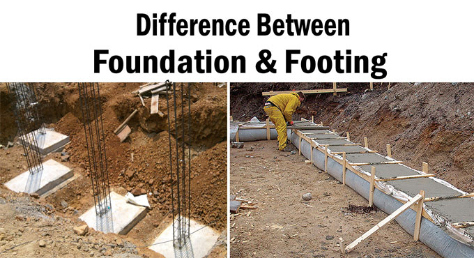
Basic differences among foundation & footing

Foundation: It is the portion of a building that is built up underneath the ground level and keeps direct contact with sub-strata. It transfers the complete load of the building to the subsoil in which it stands in such a manner that settlement of the soil is not collapsed in shear.
Footing: It is the bottom most part of a vertical structure (column, wall) that finally transmits the weight from walls and columns to the soil or bedrock.
Footing is mainly the segment of foundation of any modern structure.
Variation among footing and foundation
Given below, the basic variations among Footing and Foundation:
1
The footing is a formation that is in touch with the ground.
Foundation belongs to a structure that transfers its gravity loads to earth from superstructure.
2
Footing is analogized with the feet of the leg.
Foundation is compared with legs.
3
The footing refers to a type of shallow foundation.
Foundation is both shallow and deep.
4
Footing comprises of slab, rebar which are made of brickwork, masonry or concrete.
Foundation types comprise piles, caissons, footings, piers, the lateral supports, and anchors.
5
Footing reinforces support to a separate column.
Foundation stands for an extensive support since it provides support to a group of footings as a whole building.
6
A number of footings rest on a foundation.
Foundation is the support that sustains different types of loadings.
7
A footing remains under the foundation wall.
Foundations stand for the basement walls.
8
Footing directly transfers loads to the soil.
Foundation is directly related with the soil and passes it on the ground.
9
All footings are foundations.
Not all foundations are footings.
Basic differences among foundation & footing

~~~~~~~~~~~~~~~~~~~~~~~~~~
Published By
Rajib Dey
www.constructioncost.co
~~~~~~~~~~~~~~~~~~~~~~~~~~

Monday, August 26, 2019

Uses of prestressed concrete in civil engineering

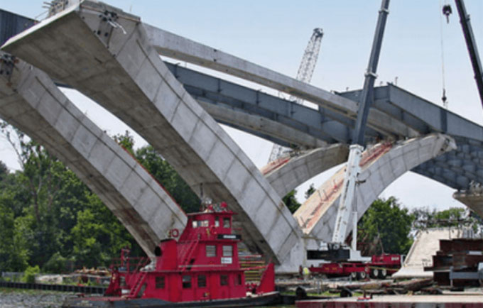
Prestressed concrete is suitable for different types of structural systems which range from pre-tensioned and post-tensioned structures, both cast-in-place and precast, and other pre-stressed components along with normally reinforced concrete.
Pre-stressed and precast concrete is divided in following four major categories:
• Standardized Elements
• Fixed Cross Section Elements
• Fully Engineered Elements
• Precast Nonprestressed Elements
Standardized Precast Prestressed Elements
Pretensioned concrete beams and slabs are normally built up in recyclable steel forms in a precast plant. Though a humble amount of custom formwork is utilized at precast plants, but when standardized components are utilized, the quality becomes better and the costs are decreased.
They comprises of standard sections like single-T and double-T beams, box girders, hollowcore slabs, inverted T-beams, and bridge girders. With the capital investment, it is possible to build up and equip a precast plant with the concrete mixing equipment, forms, stressing beds, curing systems, and heavy lifting equipment.
To increase ROI, the forms and stressing facilities should be applied continually. By improving the production process, the precast pieces can be fabricated on a routine and regular basis.
The cost efficiencies of this type of fabrication allow the architects and engineers to choose the sections for an extensive range of applications and ensure accessibility and competitive cost. Hollowcore planks, single-T, and double-T beams are applied as floor elements in building construction.
Fixed Cross Section Elements
The design engineer takes the responsibility to find out the pre-stressing forces and tendon locations in fixed cross section situations. Two common fixed section design conditions belong to post-tensioned beams and slabs for developing or parking garage construction, and girders for bridge construction.
Other uses of fixed section components range from structures like water tanks and post-tensioned slabs on-ground.
Fully Engineered Elements
For fully engineered elements, there should be constant detailed engineering all through design and construction. Instances of fully engineered structures are segmental bridges, specialty transit structures, tanks, towers, stadiums, floating facilities, and unusual building construction. The design of these structures is based on significant engineering effort as well as on-site inspection.
The intricacy of these structures requires the basic understanding of structural behavior, loads, prestressing effects, and material behavior. Collaboration of efforts among engineers, precast plants, and general contractors is essential.
Precast Nonprestressed Elements
The significant variation in grouping is that pretensioned elements need significant plant capitalization and stressing beds. Precast pieces are fabricated on the jobsite or in a facility devoid of stressing beds and other equipment related to a plant operation. Tilt-up walls are good instances of on-site precasting.
If a small amount of prestressing is necessary for delivery, erection or final loads, it is arranged in the form of single-strand post-tensioned tendons. The instances of precast nonprestressed elements are architectural precast panels and tilt-up construction. Architectural precast panels are utilized either as structural elements or the exterior finish of buildings.
Uses of prestressed concrete in civil engineering
~~~~~~~~~~~~~~~~~~~~~~~~~~
Published By
Rajib Dey
www.constructioncost.co
~~~~~~~~~~~~~~~~~~~~~~~~~~
Some useful guidelines for RCC slab design

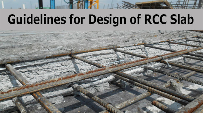
In this exclusive civil engineering tutorial, you will get some useful guidelines for designing any RCC slab.
A) Effective span of slab – It should be least of the two
1) L = clear span + d (effective depth)
2) L = Center to center spacing among the support
B) Depth of slab: The depth of slab is influenced by bending moment and deflection criterion. The trail depth is achieved with the following :-
Effective depth d = Span/((L/d) Basic x modification factor)
To get modification factor, the percentage of steel for slab is taken from 0.2 to 0.5.
The effective depth d of two slabs is also taken as cl.24.1,IS 456 on the condition that short span is 3.5m and loading class is <3.5KN/m2.
Categories of supports: Fe-250 – L/35, Fe-415 – L/28
Continuous support: Fe-250 – L/40, Fe-415 – L/32
The following thumb rules are commonly applied :-
One way slab d = (L/22) to (L/28). Two way simply supported slab d = (L/20) to (L/30). Two way restrained slab d = (L/30) to (L/32)
Load On Slab: The load on slab contains dead load, floor finish and live load. The loads are measured according to unit area (load/m2).
Dead Load = D x 25 kN/m2 (Here D denotes thickness of slab in m). Floor finish (taken as) = 1 to 2 kN/m2. Live load (taken as) = 3 to 5 kN/m2 (based on the occupancy of the building)
Nominal Cover
For mild exposure – 20 mm
For moderate exposure – 30 mm
When the diameter of bar does not go beyond 12 mm or cover is decreased by 5 mm. For main reinforcement up to 12 mm diameter bar and for mild exposure, the nominal cover is 15 mm.
Least reinforcement: The reinforcement in either direction in slab should not remain under :-
0.15% of the total cross sectional area for Fe-250 steel. 0.12% of the total cross sectional area for Fe-415 & Fe-500 steel
Distance of bar: The maximum distance of bars should not surpass. Main steel – 3d or 300 mm which is lower. Distribution steel – 5d or 450 mm whichever is lesser
Here, d denotes the effective depth of slab. The least clear spacing of bars should not be under 75 mm (desirably 100 mm). Highest diameter of bar. The highest diameter of bar should not go over D/8, here D denotes the total thickness of slab.
Some useful guidelines for RCC slab design

~~~~~~~~~~~~~~~~~~~~~~~~~~
Published By
Rajib Dey
www.constructioncost.co
~~~~~~~~~~~~~~~~~~~~~~~~~~
Saturday, August 24, 2019

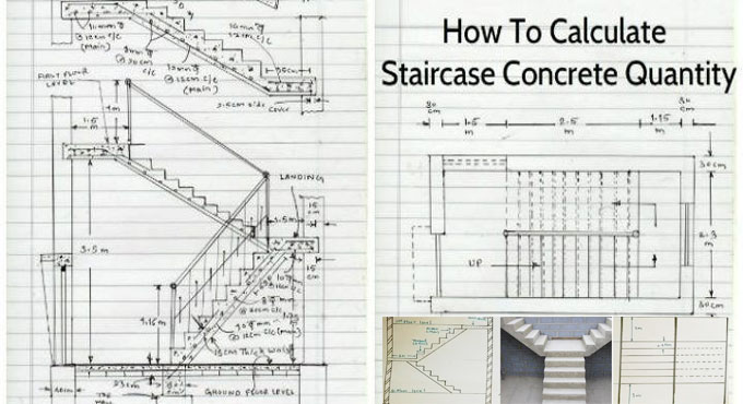
Calculation Method of Concrete Quantity for a Staircase

In order to work out the quantity of a staircase, it is required to determine the concrete volume for the followings :-
• Steps and waist slab of 1st flight
• Steps and waist slab of 2nd flight, and
• Landing
Concrete volume for 1st flight of the staircase: The calculation is done based on the following dimensions :-
Riser = 6 inches
Tread = 10 inches
Length of a step = 4 feet
Number of steps = 9
The thickness of the waist slab = 6 inches
Concrete volume for the waist slab: To get the concrete volume for the waist slab, the inclined length of the waist slab be measured first. Inclined length of waist slab can be measured from the architectural plan.
The horizontal length of a waist slab is determined by,
=number of steps x tread
= 9 x 10”
= 7′-6”
The height of the landing top from floor is,
= number of riser x height of riser
= 10 x 6″ [number of riser = number of steps = 1]
= 5 feet
Therefore, the inclined length of the waist slab should be as follow :-
=√{(horizontal length)2 + (Height)2}
= (7’-6”)2 + (5’)2
= 9’ (round up)
Therefore, the concrete volume for the waist slab should be calculated with the following formula :-
= inclined length of waist slab x width of waist slab (width of a step) x thickness of waist slab
= 9’ x 4’ x 6”
= 18 cubic feet
Concrete volume for steps: Since steps come as triangular shape, so the volume of a step should be as follow :-
= ½ x tread x riser x length of a step
= ½ x 10” x 6” x 4
= 0.84 cubic feet
As there are 9 numbers of steps in a flight, therefore, the concrete volume for the steps of the first flight should be as follow :-
= 9 x 0.84
= 7.56 cubic feet
Therefore, the entire concrete volume for the 1st flight of the staircase should be computed as follow :-
= Waist slab concrete + steps concrete
= 18 + 7.56
= 25.56 cubic feet
Concrete volume for 2nd flight of the staircase: In case the 1st flight and 2nd flight are equivalent in drawing, the concrete volume will be similar. That is,
= 25.56 cubic feet
Concrete volume for the stair landing: The calculation is done on the basis of the following dimension :-
Length of landing = 8’-6”
Width of landing = 4’-6”
The thickness of landing = 6”
Therefore, the concrete volume for the landing will be as follow :-
= 8’-6” x 4’-6” x 6”
= 19.12 cubic feet
Therefore, the total concrete volume for the staircase should be as follow :-
= 1st flight concrete + 2nd flight concrete + landing concrete
= 25.56 + 25.56 + 19.12
= 70.24 cubic feet
Calculation Method of Concrete Quantity for a Staircase
~~~~~~~~~~~~~~~~~~~~~~~~~~
Published By
Rajib Dey
www.constructioncost.co
~~~~~~~~~~~~~~~~~~~~~~~~~~
Friday, August 23, 2019

Details about structural and non structural defects in buildings

Concrete has diversified nature. It casts in place by including or excluding reinforcement. It is also precast or pre-stressed to attain necessary strength. For this purpose, there should be adequate knowledge on the behavior and constituents based on which the concrete is produced.
There should not be any type of laxity in any of its phase like placement, design & maintenance as these can create deterioration and resist concrete to accomplish its proposed functions. Given below, some vital factors which can weaken the quality of concrete:
1. Accidental loading
2. Chemical reaction like sulfate attack, alkali carbonate reactions, alkali silica reactions etc
3. Erosion of steel reinforcement
4. Inferior construction detailing
5. Erosion
6. Freezing and Thawing
7. Shrinkage
8. Settlement
9. Fire and weathering
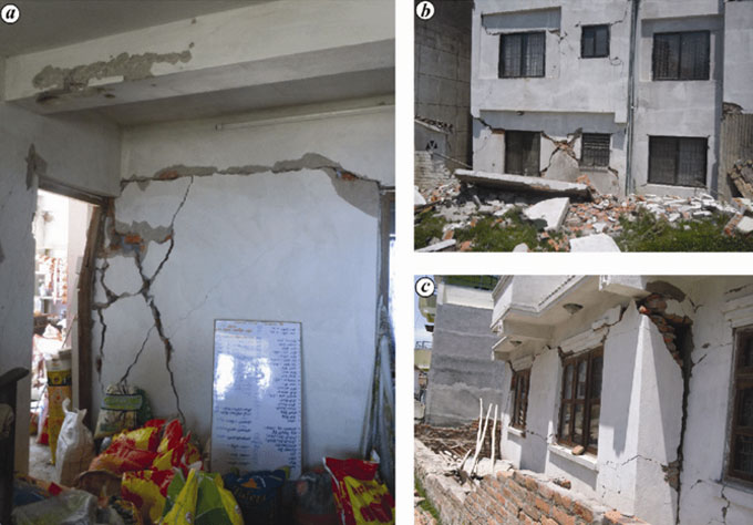
Flaws in Building Design: Due to deficient structural design, the concrete is uncovered to flexural and shearing stresses and as a result spalling and cracking of concrete are developed. Any sudden modification in cross section of any member can result in raising the stress concentration in that member that leads to cracking of concrete.
Deflection is considered as one of the significant part in structural design. If there exist any issue in its consideration throughout design, that can produce cracking of concrete. Insufficient arrangement of drainage and expansion joints throughout the design also leads to deterioration and spalling of concrete.
Flaws During Construction: Flaws throughout building construction vary from inappropriate mixing, placing and curing of concrete. Detachment of shoring & formwork can also produces cracks in concrete.
When extra water is provided in concrete to enhance the workability of concrete, the water cement ratio is raised significantly and it can reduce the strength of concrete. Inappropriate alignment of formwork produces corrosion in concrete.
Structural Defects in Building Construction - The following structural defects are found in buildings:
1. Cracks in foundation (substructure)
2. Cracks in floors and slabs (superstructure)
3. Cracks in Walls (superstructure)
These above defects are occurred due to the following factors:
1. Inappropriate soil analysis
2. Inappropriate site selection
3. Application of defective materials
4. Inferior work
These structural issues can be resolved with perfect design and planning.
Non Structural Defects in Building Construction - The following non structural defects are common in buildings:
1. Defects in brick work
2. Dampness in old structures
3. Defects in plaster works
So, it is found that minimum design and construction defects lead to minor cracking or spalling which can weaken the concrete and result in collapsing of the structure. To get rid of these issues, proper care and attention should be taken in designing, detailing and construction of concrete structure.
Details about structural and non structural defects in buildings
~~~~~~~~~~~~~~~~~~~~~~~~
Published By
Rajib Dey
www.constructioncost.co
~~~~~~~~~~~~~~~~~~~~~~~~

Commonly used Indian Standard Codes (IS codes) for civil engineers

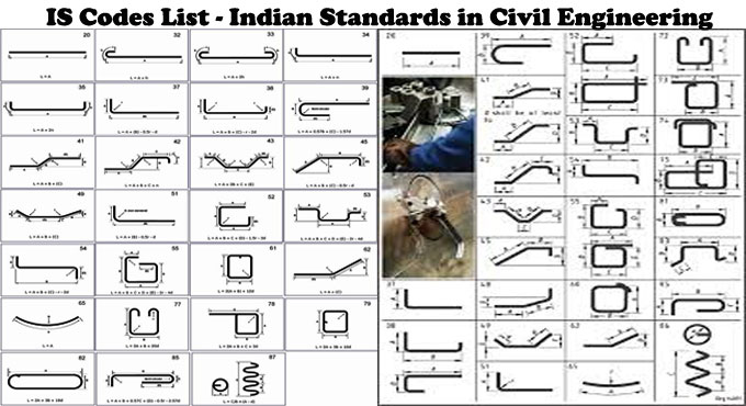
IS stands for Indian standard. Each country possesses their own code book identical to that India contains IS code book for RCC, steel structure. The IS codes includes numerous standards and methodology for construction, raw material used, structural analaysis and other provisions.
It comprises of some data based on which a civil engineer design the structure. It contains some pre defined formulae and data.
Civil engineers who perform construction activities of big projects generally should be well versed with a wide array of IS codes since such projects require different types of construction materials in several structures like buildings, roads, steel structures, all sorts of foundations etc.
Given below, detailed lists of some IS codes which are extensively used by construction engineers.
IS 456:2000: Plain and Reinforced Concrete - Code of Practice (Download link bit.ly)
IS 383:1970: Specifications for fine & coarse aggregate from natural sources for concrete (Download link drive.google.com)
IS 2386 (Part I) 1963: Methods of Test for Aggregates for Concrete, Part I: Particle Size and Shape (Download link drive.google.com)
IS 2386 (Part II) 1963: Methods of test for aggregates for concrete, Part II: Estimation of deleterious materials and organic impurities (Download link drive.google.com)
IS 2386 (Part III) 1963: Methods of test for aggregates for concrete, Part 3: Specific gravity, density, voids, absorption and bulking (Download link drive.google.com)
IS 2386 (Part IV) 1963: Methods of test for aggregates for concrete, Part 4: Mechanical properties (Download link drive.google.com)
IS 2386 (Part V) 1963: Methods of Test for Aggregates for Concrete, Part V: Soundness (Download link drive.google.com)
IS 2386 (Part VI) 1963: Methods of test for aggregates for concrete, Part 6: Measuring mortar making properties of fine aggregates (Download link drive.google.com)
IS 2386 (Part VII) 1963: Methods of Test for Aggregates for Concrete, Part VII: Alkali Aggregate Reactivity (Download link drive.google.com
IS 2386 (Part VIII) 1963: Methods of Test for Aggregates for Concrete, Part VIII: Petrographic Examination (Download link drive.google.com)
IS 2430-1986: Methods for Sampling of Aggregates for Concrete (Download link drive.google.com)
IS 4082-1996: Recommendations on stacking and storage of construction materials and components at site (Download link drive.google.com/)
IS 2116-1980: Sand for masonry mortars – Specifications (Download link drive.google.com)
IS 269-1989: Specification for Ordinary Portland Cement, 33 Grade (Download link drive.google.com)
IS 8112-2013: Specification for 43 grade ordinary Portland cement (Download link drive.google.com)
IS 12269-1987: Specification for 53 grade ordinary Portland cement (BI-LINGUAL) (Download link drive.google.com)
Commonly used Indian Standard Codes (IS codes) for civil engineers
~~~~~~~~~~~~~~~~~~~~~~~~~~
Published By
Rajib Dey
www.constructioncost.co
~~~~~~~~~~~~~~~~~~~~~~~~~~
Thursday, August 22, 2019

Some vital guidelines for measuring staircase dimensions and designs

A staircase mainly includes a series of steps which involve a tread (the horizontal portion, where the foot stands) and a riser (the vertical portion).
In every step, there are one or more landings, handrails, and a small nosing. The latter obtrudes from the tread over the lower step, facilitating to raise its size devoid of inclusion of centimeters to the overall dimensions of the staircase.
By using the following formula, find out the exact dimensions of a convenient and efficient staircase in accordance with its use.
2 Risers + 1 Tread = 63-65 cm
The required space to attain these optimal dimensions is unavailable sometimes, but it's suggested to approach them as much as possible.
A schematic illustration of a steep and low-transit staircase.
(2 x 21) + (1 x 21) = 63 cm
A schematic illustration of an optimal staircase.
(2 x 18) + (1 x 28) = 64 cm
A schematic illustration of a loose staircase, desirably for exterior application.
(2 x 13) + (1 x 39) = 65 cm
Sample measurement of a staircase that should be 2.60 meters high.
1. Workout the required number of steps - Assume an ideal riser of 18 cm, the height of the space is divided with the height of each step. The result should always be rounded up:
260/18 = 14.44 = 15 steps
2. Workout the height of every riser - The height of the space is divided with the number of steps already acquired:
260/15 = 17.33 cm height for each riser.
3. Workout the width of the tread - It can be calculated with the following formula:
(2 x 17.33 cm) + (1 x tread) = 64
Each tread will be computed as 29.34 cm
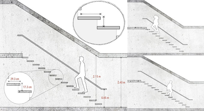
The consequential staircase will contain 15 steps of 29.34 cm of tread and 17.33 cm of riser.
Based on the use and local regulations, there should be a minimum width of 80 cm for stairs in single-family homes, and more than 1.00 meters in public buildings.
Preferably, a stairway shouldn't contain in excess of 15 steps in a row. After 15 steps, a landing should be arranged. It's suggested that a landing is calculated minimum the same as 3 treads.
The height among the steps and the ceiling should remain 2.15 meters at minimum. The height of the handrail differs among 80 and 90 cm from each step.
Some vital guidelines for measuring staircase dimensions and designs
~~~~~~~~~~~~~~~~~~~~~~~~~~
Published By
Rajib Dey
www.constructioncost.co
~~~~~~~~~~~~~~~~~~~~~~~~~~