adsense analytic

Friday, August 31, 2018

Definition and categorisation of Pre-Stressed Concrete

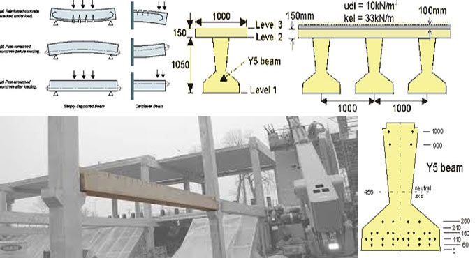
Normal concrete structure contains greater compressive strength and very weak tension strength. For the purpose of removing the weakness of concrete in tension, pre-tensioning method is applied. Pre-stressed concrete belongs to the autonomous formation of permanent compressive stresses in a structure to enhance its behavior and strength toward different service situations.

Categorization of Pre-stressed concrete

Pre stressed concrete structure is categorized on the basis of their features of design and construction. The are categorized into the following three groups.

1. Location of construction
2. Level of construction
3. Method of pre-stressing


LOCATION OF CONSTRUCTION
Here, the pre-stressed structure may come as precast cast, cast in situ, composite constrictions.


PRE CAST
Precast pre-stressed components are fabricated in a plant or adjacent to the working site. Then they are conveyed to construction site and then they are constructed and set to its position.


CAST IN SITU
The cast-in-situ concrete is standard concrete that is poured into the exact formwork on the site and cured to attain the strength of RCC elements. So, the transportation and erection process are not necessary in this method.


COMPOSITE CONSTRUCTION
Composite construction is done by integrating both prestressed and cast in situ methods. As for instance, in a beam in a building structure is built up by pre-stressed concrete and the top roof slab is built up by the cast in situ method.


LEVEL OF PRE-STRESSING
Level of pre-stressing is categorized as completely pre-stressed, limited pre-stressed, partially pre-stressed.


FULLY PRE-STRESSED
In fully pre-stressed concrete members, there is not any tensile stress under the operation of working or service loads.


LIMITED PRE-STRESS
Members are pre-stressed to a limited extent in order that members may create some tensile stress under working loads but the magnitude is below the tensile strength of concrete. These members function as a completely pre-stressed member and remain uncracked under working loads.


PARTIALLY PRE-STRESSED
Partially pre-stressed structure contains both pre-stressing steel and reinforcing steel to withstand working load.


Partial pre-stressing is useful for both pre-stressed concrete and reinforced concrete. The tensile stress remains within the limit.

To get more detail, go through the following link learntocivilfield.com
Definition and categorisation of Pre-Stressed Concrete

~~~~~~~~~~~~~~~~~~~~~~~~
Published By
Rajib Dey
www.constructioncost.co
~~~~~~~~~~~~~~~~~~~~~~~~
Thursday, August 30, 2018

EdiLus-RC – A powerful software for concrete design & reinforced concrete structural calculation

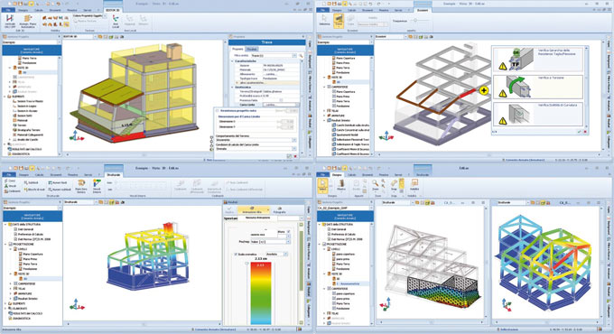
EdiLus-RC is an exclusive software for making perfect concrete design that deals with structural calculations toward new and subsisting buildings in reinforced concrete by means of the most simple and effective SMART BIM object input.

The first structural calculations BIM software for reinforced concrete buildings.

To use the software, just draw the structural members to input nodes, loads, constraints… the computational model is fully ascertained from the drawing automatically.

With this software, it is possible to design and measure new buildings as well as accomplish checks and structural redevelopments of subsisting reinforced concrete buildings with cladding work, platings, FRP interventions, etc. Particular functions will help in obtaining information concerning the subsisting structure, the material strengths defining its reinforcements.

It is also possible to insert new roof structures to the subsisting building, elevations, or even extra floors, etc., and then move on to an overall validation.

Finite Element Method solver integrated in the software: A FEM solver is added with the software to provide a unitary experience in structural design. Graphical input, the static and dynamic calculations, structural analysis, modifications and construction documents (charts, tables and reports) are all created with the very same software in a simple and incorporated manner.

Graphical analysis of the calculation results: Each object is illustrated with its stress and deformation values once the calculation process is completed. Besides, the detailed calculation leads to numerical form, EdiLus also offers different graphical views that facilitate you to realize how the structure functions at a glance. The process for improvidngh the static or dynamic behaviour of the structure is simple and intuitive.

Object oriented modelling, 3D input based on Magnetic Grids: Design with intelligent objects that comprises of information concerning their characteristics of resistance and spatial location.

The complicated spatial structures can now be easily modeled with Magnetic Grids, the robust tool that facilitates you to develop a network of magnetic points in space where the different structural components are automatically attached.

Automatic reinforcement schedules design: EdiLus can design the reinforcement schedules for all structural members efficiently. A trouble-free and robust editor that facilitates you to freely adjust the reinforcement bars even after the calculation with an immediate re-verification of the structural element.

Structural checks and Technical Reports: EdiLus-RC examines structural elements sections as per the EUROCODES technical provisions and regulations. Structural engineers can easily select the national annex and the response spectrum concerning the country in which the calculations should be done.

Cost Estimating integrated with structural design: The modelled structure creates a dynamic Bill of Quantities automatically, in reality, the complete project, and any consequent variations, are instantly updated in the project’s cost estimate.

Incorporation with the Edificius BIM model: With integration of EdiLus in Edificius, Architecture and Structural engineering issues can be easily interacted facilitating the structural engineer to design and compute all the structural elements precisely.

To download a free trial version, click on the following link www.accasoftware.com

EdiLus-RC รข€“ A powerful software for concrete design & reinforced concrete structural calculation

~~~~~~~~~~~~~~~~~~~~~~~~
Published By
Rajib Dey
www.constructioncost.co
~~~~~~~~~~~~~~~~~~~~~~~~
Wednesday, August 29, 2018

Some useful tips for repairing foundation of a building

The house gets damaged in long run and various issues occur in foundation which range from development of cracks, walls caving in, water seeping or water leaking in courtyard, cracks in foundation and irregular floors. In order to maintain the longevity of the house, the repairing work should be started immediately. A house is mainly based on foundation and if issues arise with foundation, proper care should be taken.

Given below, some useful remedies for foundation repair -

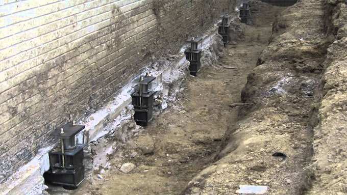
Wall Anchor Systems: When the walls of the building protrude, caves in or slide at the bottom, it indicates that the pressure on side walls is raised. To get rid of the issue, it is useful to apply wall anchor systems to provide support to the damaged wall and it neutralizes the pressure and settles the wall and even provides support to walls.

It can be adjusted based on the specifications of the building. The wall anchors can be set up instantly and finished in a day.

Crawl Space Support System: Crawl space support system provides support to the sagging floors and undersized beams recovering strength as well as straighten the beams. It rectifies the sloping floors, interior wall cracks and door to door levelling.

Pier Systems: The purpose of pier systems is to resolve issues with settling foundations and it redresses different types of settlement issues like horizontal or vertical cracks, sinking slab floors, jamming doors and windows etc. The product can be set up instantly and helpful with minimum noise disturbance.

Mud Jacking: Mud jacking refers to a method that adjusts the sinking slabs of patios, walkways, driveways and concrete steps. The mortar mix is injected among the layers to avoid sinking of the base and it is layered in the empty spaces and after getting solidified, it elevates the slab.

Structural Support Jacks: The objective of structural support jacks is to repair sagging crawl space and recovers the structure to original shape devoid of reconstructing it. It adjusts sinking crawl space supports, imperfect structural design, rotting floor beams and foundation failure.

Foundation Replacement: For replacing the entire foundation, the soil is excavated from the foundation and the adjacent areas and the house is jacked up on temporary setups. New foundation is constructed and house is lowered to recover on the foundation and other spaces are repaired as much as possible. But, the process is costly and laborious.

Commercial Helical Anchors: Commercial Helical Anchors offers sound lateral strength to foundations and balances the structure against the pressure of earth. The installation method is simple and it can be set up all the year round. The load strength can be discarded once the installation is finished.

Repair of Sinking Concrete Floors: There are two systems to repair the sinking concrete floors which range from slab pier system and lifting settled floor by injecting high density expanding foam underneath the slab that fills the empty spaces inside and it uplifts the structure back to its original position.

Steel I-Beams: The purpose of Steel I-Beams is to modify when foundation walls start bending or caving inside so that the walls are not collapsed in near future. Steel I-Beams settles the foundation wall and resolves the issue.

Repair of Street Creep Issues: Street creep belongs to a foundation issue that happens because of enlargement in heat and contraction in winters. The empty space is formed and the joints crack and debris get through the spaces thus it fails to keep its original shape in contraction. Street creep is rectified with the process of Wall anchor system.

Some useful tips for repairing foundation of a building

Read more

~~~~~~~~~~~~~~~~~~~~~~~~
Published By
Rajib Dey
www.constructioncost.co
~~~~~~~~~~~~~~~~~~~~~~~~

Tuesday, August 28, 2018

Different types of loads for designing bridge structures

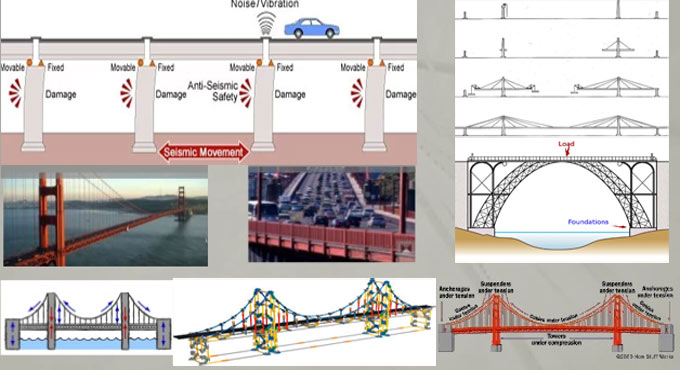
While designing bridge structure, different types of loads are taken into consideration. The protection of the bridge construction throughout its use under all situations is mainly dependent on those loads and their combinations.

The role of design loads is very important for creating exact design of bridge. Given below, various types of design loads operating on bridges :-

1. Dead load
2. Live load
3. Impact load
4. Wind load
5. Longitudinal forces
6. Centrifugal forces
7. Buoyancy effect
8. Effect of water current
9. Thermal effects
10. Deformation and horizontal effects
11. Erection stresses
12. Seismic loads


1. Dead Load: The dead load stands for a self-weight of the bridge components. The various components of bridge range from deck slab, wearing coat, railings, parapet, stiffeners and other utilities. While creating the design of bridge, it is considered as the first computable design load.

2. Live Load: The live load on the bridge belongs to the moving load on the bridge all through its length. The examples of moving loads are vehicles, Pedestrians etc. But, it is complicated to choose one vehicle or a group of vehicles to design a safe bridge.

IRC suggested some fictional vehicles as live loads which will provide secure results in anticipation of any type of vehicle moving on the bridge. The vehicle loadings are classified as follow :-

• IRC class AA loading
• IRC class A loading
• IRC class B loading


IRC Class AA Loading: This type of loading is applicable to create the design of new bridge particularly heavy loading bridges ranging from bridges on highways, in cities, industrial areas etc. In class AA loading normally the following types of vehicles are taken into consideration :-

• Tracked type
• Wheeled type


IRC Class A Loading: This type of loading is applicable for creating the design of all permanent bridges. It is treated as standard live load of bridge. While designing a bridge with class AA type loading, then it should be examined for class A loading also.

IRC Class B Loading: This type of loading is applicable for making design of temporary bridges like Timber Bridge etc. It is treated as light loading.

3. Impact Loads: The Impact load on bridge occurs because of sudden loads which are produced when the vehicle is moving on the bridge. When the wheel is in motion, the live load will alter occasionally from one wheel to another that produces the impact load on bridge.

The impact loads on bridges are assessed with an impact factor. Impact factor stands for a multiplying factor that is based on several factors like weight of vehicle, span of bridge, velocity of vehicle etc.

To get more details about other types of loads, go through the following link theconstructor.org

Different types of loads for designing bridge structures

~~~~~~~~~~~~~~~~~~~~~~~~
Published By
Rajib Dey
www.constructioncost.co
~~~~~~~~~~~~~~~~~~~~~~~~
Monday, August 27, 2018

Some crucial technical drawings terms in construction

Given below the details lists of technical drawings terms essential at construction site.

1. Tender drawings: These types of drawings are provided to the bidders at the tender time to estimate the blank BOQ. It should be studied in accordance with specifications to exact pricing of the BOQ. As for instance, sometimes supports are not cited in tender drawings but if it is given in specification, bidder should take the cost of that supports into consideration at the time of estimating the specific item.

Tender drawings & specifications play an important role in the post contract phase to manage variations.

2. IFC Drawings: It is the abbreviation of “Issued for construction”. This type of drawing is submitted by the consultant for construction purposes and formation of shop drawings to the contractor. Sometimes, the drawings are circulated for reference and information purposes. They are called as “Issued for reference” (IFR) and “Issued for Information” (IFI) respectively.

3. Architectural Drawings & Structural Drawings: These two drawings are responsible to determine the strength of the construction. Generally, the architects create the architectural drawings and the structural engineers create the structural drawings. Mainly, the architects put the client’s requirement into paper. Structural engineers take the responsibility to check that the architect’s design is structurally secure. Both the drawings are dependent on each other.

4. Interior Design Drawings (ID drawings): It offers the details or the interior structure of the construction project. For the commercial building projects it is very important. To provide standard interior to the project, exact coordination with other trades is essential.

5. Shop drawings: It is arranged by the service provider as well as sometimes by Sub-contractor or supplier. The shop drawings provide proper guidance to the people who are executing the actual work at the construction site.

It contains more details as compared to other construction drawings. When MEP Sub-contractor creates shop drawings, he has to submit the IFC, ID drawings, Architectural Drawings & Structural Drawings to make the coordination perfect.

6. Request for Information (RFI): It is extensively applied in construction industry. While generating the shop drawings, if the contractor detects any inconsistency, he should inform it to the consultant for modification. It is called as RFI. The response should be utilized for the continuous process.

7. As-built drawings: The contractor arranges these drawings as soon as the works at construction site are completed. These drawings indicate the actual construction of the project. These drawings are utilized for the final account purposes and the maintenance purposes.

Some crucial technical drawings terms in construction

Read more

~~~~~~~~~~~~~~~~~~~~~~~~
Published By
Rajib Dey
www.constructioncost.co
~~~~~~~~~~~~~~~~~~~~~~~~
Friday, August 24, 2018

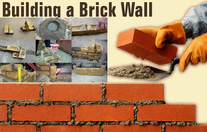
Some useful tips on proper bricklaying process

Bricklaying is treated as one of the most vital construction skills specifically when the structural walls are constructed.

In this useful construction article, you will learn the step-by-step methods to construct a garden wall. The steps involve setting out the footprint and maintaining level and square to blend the mortar, bedding the bricks and finishing joints efficiently.

Prior to start the project, find out the number of necessary bricks. Standard types are 215mm x 102.5mm x 65mm.

To obtain a perfect result, there should be 10mm mortar bed. Now, enter your brick size as 225mm x 102.5mm x 75mm for standard products.

The following equipments will be required for this purpose :-

1. Brick trowel
2. Old board
3. Tape measure
4. Spirit level
5. Brick/string line
6. Shovel

7. Club hammer
8. Bolster
9. Stiff brush


Step 1: As soon as the foundation is set properly, arrange the bricks at both ends of the wall where the pillars will be constructed. With the help of the string line, create a straight guideline at brick height among the two exterior bricks.

Step 2: Stack five shovels filled up with sand and one of cement on an old board. Turn shovel for being blended with a uniform color. Create a central hollow, pour in water and mix. Reiterate the steps unless a smooth, creamy texture is produced that’s wet but not excessively loose.

Step 3: Place a 1-2cm mortar bed along the string line. Start from one end, place the first brick and tap a little to ‘bed in’. ‘Butter up’ one end of the next brick with mortar and abut it to the first. Reiterate with string line as a guide.

Step 4: At the point where the pillars should be located, arrange a brick side-on to the end of the wall. While constructing the wall, each successive course of pillar bricks should be placed in the opposite direction.

Step 5: While constructing pillars, at specific courses, it is required to place half-bricks. To create a cut, arrange the brick on its side, trace the bolster at the split point and strike the head tightly by a club hammer. It should rupture neatly first time.

To get more details, go through the following link self-build.co.uk

Some useful tips on proper bricklaying process


~~~~~~~~~~~~~~~~~~~~~~~~
Published By
Rajib Dey
www.constructioncost.co
~~~~~~~~~~~~~~~~~~~~~~~~
Thursday, August 23, 2018

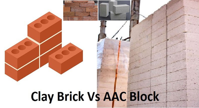
Basic differences among AAC Blocks and Red Bricks

Red Bricks are mostly recognized materials for building all through the world since they are inexpensive, long-lasting as well as simple to deal and work with.

The other vital features of red bricks range from superior stability and strength, low weight and greater ecological green features.

AAC Blocks and Red Bricks both are essential building materials for constructing walls. Red bricks & AAC blocks are utilized in walls according to their properties, accessibility and cost. Given below, the basic differences among red bricks and AAC blocks.

01. GENERAL: Red Bricks

• A Red brick stands for a block, or a single unit of a ceramic material that is applied in masonry construction, normally amassed collectively or placed with different types of mortar to retain the bricks jointly and develop a permanent structure.
• Bricks are generally formed in common or standard sizes in mass quantities.

AAC Blocks

• The weight of AAC Blocks is light and they are cut into masonry blocks or developed larger planks and panels.
• AAC Block is comparatively homogeneous with reference to other wall unit and does not include coarse aggregate phase.


02. RAW MATERIAL: Red Bricks

• The red bricks are produced by amalgamating clay(alumina), sand, Lime, iron oxide and Magnesia.
• Natural soil is utilized for making Bricks. So, it is totally based on the quality of local soil, i.e. Top soil of Earth Crust.


AAC Blocks

• It is produced from the mixture of fly ash, cement, lime, gypsum and an aeration agent.
• The Fly ash employed in AAC Blocks production is environment friendly & cement is applied in very small amount.
• The difficulty of fly ash usage is resolved with the use of fly-ash in AAC Block.


03. Applications: Red Bricks

01. As a Structural Unit:

Red bricks are sturdy, solid, long-lasting, so, they are utilized as a structural material in various structures as given below :-

• Buildings
• Bridges
• Foundations
• Arches and cornices
• Pavements


02. As an Elegant and Finish Surface:

Bricks are utilized according to its various colours, sizes and orientations to produce diverse surface designs. As an elegant material brick is applied for the following purposes :-

• As Facing Bricks
• Architectural Purposes
• Exposed practice work


AAC Blocks

• AAC Block is applied to develop internal and external walls.
• It can also be applied as load bearing and non load bearing walls.


To get more details about other points of variations, go through the following link gharpedia.com

Basic differences among AAC Blocks and Red Bricks


~~~~~~~~~~~~~~~~~~~~~~~~
Published By
Rajib Dey
www.constructioncost.co
~~~~~~~~~~~~~~~~~~~~~~~~
Wednesday, August 22, 2018

Applications and advantages of Slag Cement in concrete construction

Slag cement stands for a hydraulic cement that is developed when granulated blast furnace slag (GGBFS) is crushed by maintaining proper delicacy and utilized to substitute a part of portland cement. It is applied as an independently batched cementitious materials.

It belongs to a restored industrial by-product concerning an iron blast furnace. It mainly contains calcium and aluminum silicates.

Molten slag deflected from the iron blast furnace is chilled instantly. It forms glassy granules that offer required reactive cementitious characteristics when crush into cement fineness.

As soon as the slag is chilled and crushed to an utilizable fineness it is preserved and transported to suppliers. Slag cement is extensively used in ready-mixed concrete, precast concrete, masonry, soil cement and high temperature resistant building products.

The slag cement can improve the functioning of concrete for a long period as well as facilitates the designers to minimize the environmental footprint of concrete whereas assuring superior performance and better stability.

Given below, the various advantages of slag cement application:

1. Superior functionality
2. Simpler placeability and finishability
3. Greater long-standing compressive and flexural strengths

4. Lowered permeability
5. ASR mitigation properties
6. Superior stability and resilience
7. More uniform performance
8. Lighter color


Specifications and Grade:

Grade 80: Slag containing a low activity index

Grade 100: Slag with a moderate activity index

Grade 120: Slag with a high activity index

Application & dosage (% by weight) of slag

Outside flatwork ≤35%
General application 35 to 50%
Mass concrete 60 to 80%


Sulfate resistance
Type II equivalent ≥ 35%
Type V equivalent ≥ 50%
Marine/chemical/heat >50%<80%


The slag cement is used in diverse ways which range from ternary mixtures and soil stabilization etc.

Applications and advantages of Slag Cement in concrete construction


Read more


~~~~~~~~~~~~~~~~~~~~~~~~
Published By
Rajib Dey
www.constructioncost.co
~~~~~~~~~~~~~~~~~~~~~~~~

Tuesday, August 21, 2018

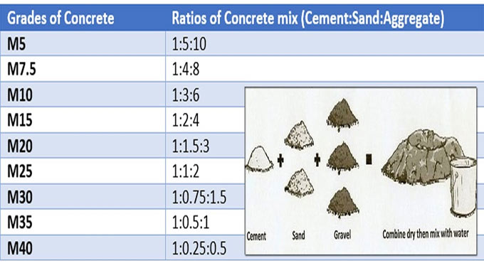
Some crucial information about concrete mix design

Mix Design refers to the method of choosing perfect materials of concrete and finding out their proportionate ratios with the purpose of developing concrete with minimum specific strength and stability as reasonable as possible.

To form concrete maintaining desired strength and properties, choosing of components and their quantity should be determined and it is defined as concrete mix design.

The site engineer should provide following information at the time of delivering material for mix design to the mix design laboratory :-

A) Grade of concrete (the characteristic strength)
B) Necessary workability regarding slump
C) Other properties (if necessary)


Retardation of initial set (to get rid of cold joints for longer leads or ready mix concrete)

Slump retention (for ready mix concrete)

Pumpability (for ready mix concrete)

Expedition of strength (in case of precast members or where initial deshuttering is required)

Flexural strength (generally necessary concrete pavements)

Determine whether condition of exposure to concrete is mild, moderately severe or very severe. Exact analysis of soil should be made to determine existence of sulphates & chlorides for any doubt.

The degree of control at construction site is based on the following factors :-

Batching – Weigh batching/volume batching

Type of aggregates – Whether the type of aggregate will be mix graded or 10 mm, 20 mm aggregates should be utilized independently.

Testing of concrete – Whether casting & testing of concrete cubes should be performed at construction site on regular basis.

Source of aggregate – Whether sources of sand and aggregate are standard or should be altered regularly.

Supervision – Whether skilled staffs are there to superintendent concreting work and make require changes like rectification of moisture in sand and alteration in material properties.

Site laboratory – Whether the site will contain required laboratory tools like sieves, weighing balance etc. for the verification of material properties.

Some crucial information about concrete mix design

Read more

~~~~~~~~~~~~~~~~~~~~~~~~
Published By
Rajib Dey
www.constructioncost.co
~~~~~~~~~~~~~~~~~~~~~~~~
Monday, August 20, 2018

How to check the quality of cement at the construction site

The quality of cement should be examined properly prior to utilize it in concrete, plastering or any other purpose at construction work site.

For quality checking, initial inspection is very crucial. It may not always feasible to check all the engineering qualities required for utilizing cement on site but the quality of cement can be checked roughly through some recognized field test in the construction site. But the other crucial tests should be performed in laboratories.

Field Tests to verify the quality of Cement

1. Date of Packing Cement: Before purchasing cement, make proper investigation regarding the date of manufacture provided on the cement bags. It is very crucial since the strength of cement is decreased with age.

2. Colour: The color of cement should be consistent. Usually, the colour of cement remains grey with a light greenish shade. The colour of cement symbolizes surplus lime or clay and the degree of burning.

3. Rubbing: Take a pinch of cement among fingers and rub it, It should appear smooth at the time of rubbing. If it feels rough, there is adulteration with sand.

4. Temperature Test of Cement: Push your hand into the cement bag and it should feel cool. It means that there is no hydration reaction in the bag.

5. Float Test: Provide a small quantity of cement in a bucket of water. It should submerge and should not float on the surface.

6. Smell Test: Select a bit of cement and smell it. If there is excessive pounded clay and silt as an adulterant in the cement, the paste will provide an earthy smell.

7. Existence of Lumps: Open the bag and check that no lumps exist in the bag. It will make sure that no setting has occured.

8. Shape Test: Select 100g of cement and make a stiff paste. Make a cake with sharp edges and placed on the glass plate. Submerge this plate in water. Verify that the shape should remain as it is at the time of settling. It should have the capability for being set and obtained strength. Cement has the capacity of being set under water also and for this reason it is known as ‘Hydraulic Cement’.

9. Strength of Cement Test: A block of cement 25 mm*25 mm and 200 mm long is arranged and absorbed for 7 days in water. It is then set on supports 15000 mm apart and it is loaded with a weight of 340 N. The block should not demonstrate any sign of failure.

How to check the quality of cement at the construction site

Read more

~~~~~~~~~~~~~~~~~~~~~~~~
Published By
Rajib Dey
www.constructioncost.co
~~~~~~~~~~~~~~~~~~~~~~~~
Saturday, August 18, 2018

Some useful tips to draw a floor plan effectively

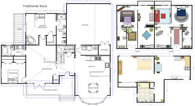
A floor plan stands for a scaled diagram of a room or building glanced from above. The floor plan may demonstrate a whole building, one floor of a building, or a single room. It may also comprise of measurements, furniture, appliances, or everything required for developing the plan.

The objective of the floor plans is to design furniture layout, wiring systems, and much more. They're also very suitable for real estate agents and leasing companies in allowing sell or rent out a space.

The benefits of Floor Plan Design

Floor plans play an important role while designing and building a home. A good floor plan can make a pleasant flow among spaces and can even enhance its resale value.

Given below, some useful features of a good floor plan

• Adaptable and flexible. Ensure that in near future an office can be transformed into a child's bedroom smoothly whether for your family or a future buyer's.

• Ideal room layout. Ensure bedrooms are distant from entertaining spaces. The face of the bathrooms shouldn't be directed to entertainment spaces like dining rooms or living rooms. Most people will prefer that the kitchen should be opened to the dining or living rooms in order that whoever is cooking can still keep in touch with guests or monitor on the kids playing.

• Size matters. While making design of any room or hallway, consider how many people will stay in that space all at once. Is there room for them to move around? Is there room for furniture to coordinate all the planned activities?

• Fits your priorities and lifestyle. If entertaining is crucial, ensure there's a good flow from the kitchen to an exterior space and living room. While going to work from home, ensure there is adequate light and home is situated in a quiet location. While performing laundry work, is it perfect to climb three floors to shift from your master bedroom to the laundry room?

• Get the balance among architectural details and practical considerations. Concentrate on the security of kids, cleaning, heating and cooling bill prior to select some majestic staircase or floor to ceiling windows.

How to Draw a Floor Plan - Given below, some useful tips to draw a floor plan:

• Select an area. Find out the area that will be drawn. If the building is already there, choose how much (a room, a floor, or the complete building) should be drawn. If the building does not yet subsist, plot out the designs on the basis of the size and shape of the location where the building should be constructed.

• Get measurements. If the building subsists, work out the walls, doors, and relevant furniture to make the floor plan perfect. If the layout is to be developed for a completely new area, ensure that the total area will accommodate where it should be constructed. It is suggested to study buildings which are constructed in identical areas to be employed as an estimate for this floor plan.

• Draw walls. Insert walls for each room of the building, keep in mind that the walls should be drawn to scale.

• Add architectural features. Start adding features to the space by providing the inflexible things, like the doors and windows, along with the refrigerator, dishwasher, dryer, and other vital instruments that should be arranged in a particular location.

• Add furniture. Include furniture if it is required for the floor plan.

Some useful tips to draw a floor plan effectively

Read Continue

~~~~~~~~~~~~~~~~~~~~~~~~
Published By
Rajib Dey
www.constructioncost.co
~~~~~~~~~~~~~~~~~~~~~~~~

Friday, August 17, 2018

Detail construction method of RCC column

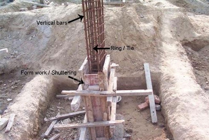
RCC (Reinforced Cement Concrete) column belongs to an inherent structural element of RCC frame structured building. It refers to vertical member that disperse loads from slab and beam directly to the soil underneath.

The entire building rests on columns. Most of the building failure happens because of the column failure. Both design error and the substandard construction practice are liable for column failure. So, there should be clear conception on the construction process of the RCC column.

The construction of the RCC (Reinforced Cement Concrete) Column is based on the following four phases of works –

1. Column layout work

2. Column reinforcement work
3. Column formwork, and
4. Pouring concrete into column.

Construction Process of RCC Column:

1. Column layout work: Under this stage, the location of columns is practically arranged in the jobsite. It is done by placing rope compliant with the grids presented in the drawing and then mark the position of the columns related to the rope.

In drawing, column locations are demonstrated according to grid-line with dimension. In construction field, the ropes are taken as grid-line. So, the columns should be placed to rope-line by calculating the dimension given in the drawing.

2. Column Reinforcement work: Once the positions of the column are marked, the reinforcement is placed with reference to the structural drawing.

It is usually stated in the drawing as following way :-

C1-12#16 mm⌀ and stirrup-10 mm⌀ @ 4″ c/c.

It indicates that column C1 will contain 12 numbers of 16 mm diameter bar as vertical bar and 10 mm diameter steel should be placed 4 inch center to center as stirrup.

or

C2-8#20 mm⌀ + 10#16 mm⌀ and stirrup-10 mm⌀ @ (4″+6“) c/c.

This C2 column’s reinforcement specification signifies that it’ll include 8 numbers of 20 mm diameter bar together with 10 numbers of 16 mm diameter bar as vertical reinforcement and (4″+6″) center to center of stirrups placement signifies that the middle-half portion of clear height of column will contain 6″ center to center spacing of stirrups and upper one-fourth and bottom one-fourth height of column’s clear height will retain stirrups at 4″ center to center spacing.

A sheet exists in structural drawing that comprises of structural notes from structural designer. In that drawing sheet, you’ll get suggested lap length for column’s steel of various diameter bar and other vital notes. One should understand those prior to column reinforcement work.

3. Column formwork: In building, floor height generally remains 10 feet. If there is beam in slab then we have to pour concrete up to beam bottom level. Assume that the height of beam in drawing is given as 1′-6″. Therefore, the casting height of the column should be 8′-6″. And the height of formwork will be 8′-6″. It should be remembered here that dropping concrete from over 5′ height isn’t recommended throughout pouring. Since it leads to concrete segregation, it is required to create one-side of column formwork within 5 feet height range. Once, 5 feet of column is cast, the short side should be lifted up to full-casting height of column next day.

Another way to cast column devoid of segregation is to maintain a small window at 5 feet level of full-height formwork. Once casting is completed up to that level, close the window and cast the remaining portion of the column.

4. Pouring concrete into column: The process is simple for casting column. For small quantity of concrete volume, machine-mix concrete is suitable and for large concrete quantity, ready-mix concrete will be preferred. If moving pump is used with ready-mix concrete and if it is required not to exceed 5 feet height range for dropping concrete that will be complicated.

If moving pump is not used, there will be some issues. Assume, it is necessary to utilize ready-mix concrete excluding pump. Under this situation, the concrete should be unloaded by hand on job site from ready-mix concrete truck and poured into column manually. It will consume long time and initial setting time of concrete will be exceeded. Because of this, concrete will lose its quality. Therefore, it is suggested to cast column with machine-mix concrete.​


Detail construction method of RCC column

Read Continue

~~~~~~~~~~~~~~~~~~~~~~~~
Published By
Rajib Dey
www.constructioncost.co
~~~~~~~~~~~~~~~~~~~~~~~~

Thursday, August 16, 2018

Some useful tips on quality control and safety in construction

A structure may collapse or becomes defective because of substandard quality control. Re-construction becomes necessary and facility operations get damaged due to even small defects.

The construction cost is raised and construction delays occur. Also, there may be personal injuries or fatalities because of collapsing of structure.

Accidents throughout the construction process can also lead to personal injuries and greater costs. Indirect costs related to insurance, inspection and regulation are also raised significantly because of these inflated direct costs.

A knowledgeable project manager is liable for completing the construction work in scheduled time and he ensures that no major accidents take place on the project.

As with cost control, the most vital decisions concerning the quality of a completed facility are taken throughout the design and planning phases in spite of construction.

It is throughout these initial phases that component configurations, material specifications and functional performance are settled efficiently. Quality control throughout construction mainly comprises of insuring conformance to these original design and planning decisions.

Besides, unanticipated circumstances, inaccurate design decisions or modifications required by an owner in the facility function will involve reassessment of design decisions throughout the course of construction. These modifications are caused by the concern for quality, they characterize occasions for re-design with all the accompanying objectives and hindrances.

Some designs are based on the reasonable and perfect decision making throughout the construction process itself. As for instance, some tunneling methods will allow taking decisions concerning the amount of shoring essential at various locations on the basis of inspection of soil conditions throughout the tunneling process. Since such decisions are taken on the basis of superior information about actual site conditions, the facility design may be economical as a result.

By giving emphasis on conformance as the measure of quality throughout the construction process, the specification of quality requirements in the design and contract documentation becomes significantly vital. Quality requirements should be concise and valid, so that all the project stakeholders can recognize the requirements for conformance.

Safety during the construction project is also a great concern for the decisions taken throughout the planning and design phase. Some designs or construction plans are indigenously critical and hazardous for execution, whereas other equivalent plans may significantly lessen the chance of accidents. As for instance, clear segregation of traffic from construction zones throughout roadway rehabilitation can considerably minimize the chance of accidental collisions. Besides, safety is mostly based on education, vigilance and cooperation all through the construction process. Proper alert should be sent to the workers repeatedly to get rid of accidents and refrain from taking nonessential risks.

Some useful tips on quality control and safety in construction

Read Continue
~~~~~~~~~~~~~~~~~~~~~~~~
Published By
Rajib Dey
www.constructioncost.co
~~~~~~~~~~~~~~~~~~~~~~~~