adsense analytic

Monday, May 13, 2019

Reason for damaging & collapsing of concrete buildings

A reinforced concrete building gets damaged and collapses due to several reasons such as sliding of roofs, falling of walls, crushing of columns, short column effects, diagonal cracking, foundation sinking and tilting etc.

Types and Causes for Damage and Collapse of Concrete Buildings.

Given below, the details about the most common types of damages in reinforced concrete buildings:

1. Sliding of Roofs off the Supports: Where the beams are just supported on walls or columns, they are susceptible to slide if the severity of earthquake surpasses the frictional resistance and several times come out of the support and collapse, specifically when the bearing length is minor.

2. Collapsing of Infill Walls: The infill panel walls amid reinforced concrete columns overturn outer the framework when they are not firmly retained or secured with the frames.

3. Crushing of Column Ends and Virtual Hinging: When extreme shaking occurs, the column ends are susceptible to serious eccentric compressive stresses which compel the concrete to get crushed and broke down from the exterior surfaces. In frequent cycles, the damage proceeds interiors, consequently the effective section is shortened significantly. Both the column ends substantially function as pins and the entire framework falls down like a mechanism.

4. Short Column Effect: If infill walls having wide openings are joined to the columns, the sections of the columns to be deformed against lateral seismic loads turn out to be very short with reference to their normal height.

Such short columns develop into much harder as compared to other columns and pull greater shear forces under which they experience extreme diagonal tension which result in collapsing of the column.

5. Diagonal Cracking in the Columns: Columns are exposed to diagonal cracking resulting from large seismic shears occurred under extreme ground shaking. When the building also sustains the twisting action, the crack may change to a spiral form that decreases load bearing strength of the columns significantly.

6. Diagonal Cracking of Column Beam Joint: Several times, diagonal cracking happens through the intersection of the columns with the beams that considerably damages the strength of the frame.

7. Drawing Out of the Reinforcing Bars: Where the anchor length of the column bars or overlaps among the longitudinal bars are insufficient for producing full tensile strength of the bar, they are frequently drawn out because of tensions occurred in the column against reversal of stresses.

8. Collapse of Gable Frames: Reinforced concrete gable frames, frequently applied for school workshops, gymnasia and assembly halls, and cinema halls, may be expanded devoid of secondary resistance obtainable as soon as a joint fails. These are frequently found to fail and collapse if not properly designed and detailed.

9. Foundation Sinking and Tilting: Sinking or tilting of foundations of columns because of seismic shaking happens in loose soft soils and can result in extreme cracking of the superstructure and even fall down.

Reason for damaging & collapsing of concrete buildings

Read more
~~~~~~~~~~~~~~~~~~~~~~~~
Published By
Rajib Dey
www.constructioncost.co
~~~~~~~~~~~~~~~~~~~~~~~~

Saturday, May 11, 2019

How to perform audit of old structures

There exist several types of public buildings with over 30 years lifespan. The stability of these buildings is decreased significantly owing to decay in materials.

On the basis of the yearly tests conducted on each public building, the weaker buildings having age over 30 years should be detected and the Assistant Executive Engineer level Officer of the related department should dispatch the list to the superior officer of the level.

Then, an inspection at the level of superintending Engineer/EE should be performed for all such building and an extensive structural audit should be carried out.

The related department should hand over the structural audit to an accredited Institution / agency and the details of which are provided below:

Usually, the Structural Audit should be performed with the following steps:

Step 1: The Architectural and Structural plans of the building are important. There should be detailed structural calculations along with assumptions for the structural design.

Step 2: When the Architectural plans and Structural plans do not exist, the similar should be arranged on the basis of site observations.

Step 3: A building should be examined thoroughly as follow :-

1. Any settlement in the building.
2. Cracks found in columns, beams and slabs.
3. Pictures of concrete disintegration and exposed steel reinforcements are useful.
4. Slight tapping with a hammer can disclose decay in concrete and wooden beams.


5. Erosion in reinforcement.
6. Status of Balconies – sagging, deflection, cracks.
7. Status of Architectural features.
8. Cracks in walls specifying swelling in R.C.C members or identification of erosion.
9. Leakages from terrace & Toilet blocks.
10. Leakages & dampness in walls which lead to cracks and corrosion.
11. Status of repairs & last repaired date.
12. What section of the structure was repaired?
13. Who was the Agency?
14. How much was incurred for repairs?
15. Are sanctioned Building plans available?


Step 4: Formulation of Audit Report:
Depending on the inspection on building, the Audit Report should be arranged.


Step 5: Tests Suggested:
It is vital that different types of tests are performed in the old buildings to get an idea about spreading of corrosion, distress and loss of strength in concrete & steel.


Step 6: Point out the major areas and repair them accordingly.

How to perform audit of old structures

Read more
~~~~~~~~~~~~~~~~~~~~~~~~
Published By
Rajib Dey
www.constructioncost.co
~~~~~~~~~~~~~~~~~~~~~~~~

Friday, May 10, 2019

Variations among nominal mix and design mix

Under Concrete mixing method, all the materials of concrete are chosen with exact ratio. The ratios of mix should be maintained in such a manner so that the workability of the fresh concrete remains perfect and when concrete is solidified, it should contain the necessary strength, surface finish and stability.

Generally, two types of methods are utilized for proportioning several materials which range from nominal mix and design mix of concrete. Based on the requirement and type of work, the types of concrete mix are chosen.

The nominal mix is the process in which all the ingredients are prescribed as per specifications and their proportions are specified in the ratio of cement to aggregates for the certain strength achievement. The nominal mix is preferred for simpler, relatively unimportant and small concrete works. In other words, the nominal mix is adopted for ordinary concrete work.

Concrete shall be called ‘Nominal mix concrete’ when it’s adopting by a mix like 1:1.5:3, 1:2:4, 1:3:6 etc. and so without any scientific basis, basis on past empirical studies.

Nominal mix normally includes volumetric batching. Generally, the ratio is determined with weight and for concreting, it is transferred to volumetric proportion, i.e. relating to 1 bag of cement that is 50 kg of cement standard measurement boxes are developed on site that is in the ratio of 1 bag of cement.

Nominal mix concrete is suitable for M20 grade concrete or lower grade like M5, M7.5, M10, M15. Here, M stands for Mix and 20 signifies the compressive strength of concrete cube after 28 days of curing in N/mm2. There are other types of concrete grades like M10, M15, M20, M25, M30 etc.

Ratios as stated by IS for Nominal Mix

The ratios of materials for nominal mix concrete should be compliant with IS 456: 2000.

The ratio of the fine to coarse aggregates should be revised from the upper limit to lower limit gradually since the grading of fine aggregates turns finer, and the maximum size of coarse aggregate turns bigger, graded coarse aggregate should be utilized i.e. for an average grading of fine aggregate (namely Zone II- IS 383- Table 4). The normal ratios are 1:1½, 1:2, 1: 2½ for the maximum size of an aggregate 10mm, 20 mm and 40 mm respectively.

With adherence to the IS 456: 2000, the ratios of the nominal mix are modified when it is required to increase the quantity of water to resolve the issues concerning placement and compaction in order that the water cement ratio is retained as specified.

Benefits:

1. The nominal mix is the prescriptive type concrete; a ratio is settled earlier.
2. It can be simply created at a construction site.
3. Require less time to fix on the ratio as the ratios are already provided with standard code.
4. No skilled persons are required for nominal mix.


Design Mix: Under design mix, the ratios of the materials of concrete are perfectly set with their relevant ratios to attain the required strength of concrete as well as several characteristics of fresh concrete like workability or performance of concrete with particular specifications. Concrete is identified as ‘Design mix concrete’ if the ratio of its materials are settled after trial and error of different option in the laboratory, after conducting the tests from the materials provided for the work.

Guidelines for Mix Design: Mix design is the authentic method for choosing the mix ratios with certain materials containing more or less unique properties. Design mix comprises of weight batching. It allows the concrete to attain required strength. It is also very inexpensive. All the materials are examined properly prior to apply in the design mix.

Properties of Ingredients are verified - Under the design mix method, it is necessary to verify each property of materials and then, the design should be commenced. The following properties of ingredients should be checked :

Cement – Cement grade, consistency, initial setting time and final setting time, specific gravity etc.

Aggregate – Density, bulking of fine aggregate, the specific gravity of fine aggregate and coarse aggregate, grading of aggregate, fineness modulus, particle size, silt content, water absorption, unit weight etc.

Benefits:

• As compared to nominal mix, design mix is more authentic.
• Mix design is suitable for more wide-ranging and vital concrete works.
• Mix design is dependent on the existing actual material to be utilized.
• When locally accessible material can meet the criteria, it should be applied for mix design concrete with the purpose of minimizing the cost of importing material from outside.
• The quantity of the applicable materials should be judicious, i.e. it’s should not be overused nor underused.
• It is made on the basis of the laboratory trial/error experiment method.
• It provides an assurance of strength.
• Mix design concrete is performance-based concrete.
• Design mix concrete is commonly utilized.
• The designer can employ admixtures reasonably to rectify the properties of concrete as per their requirement.
• Slump and strength are co-related that means for strength, several slumps can be utilized by altering water/cement ratio with or without admixtures in order to match concreting of various materials, i.e. for footing it may contain less slump, i.e. less w/c ratio, but for thin materials like chhajja or thin walls, it may require a larger slump, i.e. greater w/c ratio or more quantity of admixture. It is not feasible in the nominal mix.


Variations among nominal mix and design mix

Read more
~~~~~~~~~~~~~~~~~~~~~~~~
Published By
Rajib Dey
www.constructioncost.co
~~~~~~~~~~~~~~~~~~~~~~~~
Thursday, May 9, 2019

Detail guidelines on Structural Design Codes And Standards

Design of RCC Structural Components: In this civil engineering article, you will be familiar with the minimum standards necessary for the design of RCC structural elements of a structure like columns, beams, slab and foundation.

Besides, the information is also given on the minimum safe standards for the reinforcing bars which should be applied for the design of the above mentioned structural elements.

Minimum cross-sectional dimension for a Column: Minimum standard size should be 9″x 12″(225 MM x 300 MM). It is recommended to use M20 grade concrete for construction as per IS 456:2000. The minimum steel in a 9″ x 9″ column should contain 4 bars of 12 MM containing stirrups of 8 MM steel rings at a spacing of 150 MM centre to centre. In a 9″ x 12″ column, two more bars can be added to make the total to 6 bars of 12 MM diameter. This design will be secured for up to G+1 floors.

Minimum RCC beam size : It should not be under 9″x 9″(225MM X 225MM), containing a extra slab thickness of 125 MM.

A minimum of 4 bars can be used containing 2 bars of 12 MM thickness in the bottom of the beam, and 2 bars of 10 MM at the top of the beam. The required concrete cover should be 40 MM. It is recommended to utilize M20 grade of concrete (1 part cement : 1.5 parts sand : 3 parts aggregate : 0.5 parts water).

Minimum thickness of RCC slab : It should be minimum 5″ (125MM) as a slab may comprise of electrical pipes implanted into them with thickness 0.5″ or more for internal wiring, which in fact minimizes the depth of slab at specific areas. It leads to cracking, decay and water leakage during rains. So, there should be a minimum thickness of 5″.

Minimum size of foundation : A size of 1m x 1m should be ideal for a single storey of G+1 building, where the safe bearing strength of soil should be 30 tonnes per square meter, and the impending load on the column does not be in excess of 30 tonnes,. Minimum depth of footing should remain 4′ underneath ground level. It is recommended to retain deepness up to had strata.

Reinforcing bar details (minimum):

1. Columns: 4 bars of 12mm steel rods FE 500.
2. Beams: 2 bars of 12 mm in the bottom and 2 bars of 10 mm on the top.
3. Slab


a) One Way Slab: Main Steel 8 MM bars @ 6″ C/C and Distribution Steel of 6 mm bars @ 6″ C/C
b) Two Way Slab: Main Steel 8 MM bars @ 5″ C/C and Distribution Steel of 8 mm bars @ 7″ C/C


4. Foundation: Initially, 6″ of PCC layer should be provided. Over it, there should be a tapered or rectangular footing with minimum 12″ thickness. Steel mesh of 8 mm bars @ 6″ C/C should be placed. In a 1m X 1m footing, it should comprise of 6 bars of 8 mm on both portions of the steel mesh.

Detail guidelines on Structural Design Codes And Standards

Read more
~~~~~~~~~~~~~~~~~~~~~~~~
Published By
Rajib Dey
www.constructioncost.co
~~~~~~~~~~~~~~~~~~~~~~~~
Wednesday, May 8, 2019

How to build up an earthquake-resistant structure

Earthquake means quick shaking of the ground due to the shift of rock and tectonic plates underground. The ground appears as solid, but the topmost crust of earth is deep and long periods of time produce pressure to develop among plates and fissures.

When the pressure is applied, seismic vibrations and fierce shaking reverberate to the surface which instantly impact miles of land. Once the initial quake hits, aftershocks happen to create further damage.

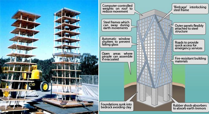
The buildings should withstand radical movement and foundation shifts so as to reduce damage and safeguard the people inside and around them. Earthquake-resistant building designs should be created based on the following characteristics which impact their structural integrity: stiffness and strength, regularity, redundancy, foundations, and load paths.

Stiffness and Strength: While creating design for earthquake-resistant buildings, safety professionals suggest sufficient vertical and lateral stiffness and strength – specifically lateral. Structures are likely to deal with the vertical movement resulting from quakes superior to the lateral, or horizontal, movement.

Devoid of taking earthquakes into consideration, professionals still concentrate on a building’s vertical stiffness and strength since it has to support itself. However, earthquakes present new directional forces and owing to these, buildings will shift left and right, and, if not constructed perfectly, will rapidly destabilize.

Regularity: This characteristic pertains to the movement of the building if pushed in lateral directions. According to safety professionals and building designers, the building should move uniformly in order to disperse the energy devoid of placing extra force on one side or another. When a building is uneven, then flaws will be detectable while the building shakes. The flaws will be settled and the structure will experience concentrated damage – which settles the structure completely.

Redundancy: It is a vital safety characteristic while designing for safety. Redundancy assures that there exist several strategies in place whether one fails. These can possibly be add to the building cost, but redundancies become vital if/when a natural disaster like an earthquake happens. Safety professionals suggest to uniformly allocate mass and strength during the structure so strength isn’t entirely dependent on one factor.

Foundations: A steady foundation is a vital characteristic of constructing a large structure irrespective of natural disaster risks. It is important for a building’s long-term existence, and a robust foundation is required to withstand an earthquakes powerful forces. Different areas have unique foundational characteristics that define how a structure’s base needs to be reinforced. Professionals should stringently monitor reactions of the ground and movement prior to starting of construction. The buildings developed to withstand fierce earthquakes contain deep foundations and driven piles. To settle these radical measures, the foundations should be joined properly to facilitate moving as a unit.

Continuous Load Path: Binding into the stable foundation characteristic, structural and nonstructural elements of a building should be interlinked in order that inertial forces are dispersed. Numerous points of strengths and redundancies distribute the force rather than the quake partitioning the foundation apart. It refers to the continuous load path characteristic that safety professionals, architects, and engineers should be aware of at the time of creating the design. When the structure is not entirely fastened jointly, elements fail to shift separately and collapsing can occur. The incessant load path is the journey of earthquake through the building – laterally and vertically. The path should be intact so that it can disperse an earthquake’s powerful shudders.

How to build up an earthquake-resistant structure

Read more
~~~~~~~~~~~~~~~~~~~~~~~~~~
Published By
Rajib Dey
www.constructioncost.co
~~~~~~~~~~~~~~~~~~~~~~~~~~

Tuesday, May 7, 2019

How to erect a bridge – some vital guidelines

Given below, some necessary stages to construct a bridge in the public works sector.

Step One: The Foundations - The purpose of foundation is to disperse different types of loads of the bridge (mass, weight, overload, forces …) perfectly based on the type of the ground of the structure.

The foundations are categorized as the following two types :-

• The superficial foundations: These foundations are ideal for the bridges with level adjacent to the ground since the structures are susceptible to reduced constraints in comparison with the wind and their gravity. It is also necessary that the rocks within the structure should be strong, undecomposed and not greatly cracked.
• Deep foundations: This type of foundation is effective while the bridge starts to obtain the height. Under this situation, it occurs consistently that the soil exposes a layer more stable in depth. At the time of construction, there are three situations which produce the following three types of foundation:


a. Referred to as “good” soil, when it allows to set the foundations directly on a durable ground, is known as flat foundation.
b. Referred to as “bad then good” soil, when it is required to place four piles in the unsteady ground unless they attain the steady ground.
c. The soil becomes “unsettled”, when the quality of soil in the ground is not good. Under this circumstance, lots of piles should be installed to provide good resistance capacity severe compression.


Without resistance at depth, the support should be provided with “floating” piles.

Second Step: Construction of Supports - The number of supports (abutments and piles) required for the construction of the bridge should be affixed concurrently on both sides of the shores. These supports are generally formed with concrete and either cast in place, or prefabricated in a factory and then assembled on site.

Third Step: Assembly and Start-Up of the Superstructure - Due to the final weight of the structure, the greater or smaller spacing among every pile and the final objective of the structure, it becomes complicated to apply the concrete for the construction of the deck which, over great distances, fall down even because of its own weight and of its traffic. For this reason, the elements of metal beams are used. These are assembled jointly to build up the structure of the deck.

On every shore, the beam elements are set up through a crane and the elements are then reconstructed with welding on site (Welded I-Beams). The deck is then provided with a launching nose, finished with a ballast at the back to resist tipping. Normally, the piles are driven with winches, cables and pulleys, the deck advances at a speed of about 9m / h. Also, this solution is substituted with restraint systems to stop runaway.

Fourth Step: Pouring the Slab - The beams are provided with connectors in the factory so that the steel structure is secured to the concrete slab of the latter. As soon as the beams are installed on their final supports, the lost formwork is arranged on them along with reinforcement prior to pouring a layer of concrete with thickness of about 25cm that will be the slab of the structure.

Step Five: Finishes - To complete the work, after several months, even years of construction, the final step is to provide asphalt on the road. Asphalt stands for a very specialized type of bitumen to resist expanding of deck. Thus, even with some deformations of steel, the bitumen will not crack and retain the quality to adapt the road traffic.

Several sensors are arranged on each strategic part (deck, cable stay, piles, pylons …) and facilitate to constantly follow the state of the bridge.

How to erect a bridge – some vital guidelines

Read more
~~~~~~~~~~~~~~~~~~~~~~~~~~
Published By
Rajib Dey
www.constructioncost.co
~~~~~~~~~~~~~~~~~~~~~~~~~~

Monday, May 6, 2019

How to calculate number of tiles for a floor

A tile is mainly a thin object usually square or rectangular in shape and it is a manufactured piece of hard-wearing material like ceramic, stone, metal, baked clay or even glass which is generally used for covering roofs, floors, walls or other objects like tabletops. Tiles are often used to form wall and floor coverings and can range from simple square tiles to complex or mosaics.

Floor Tiles are mainly used in Residential buildings to make every possible thing beautiful; engineers used them almost everywhere like in stairs, lobby, apartment, roof etc. Though floor tiles are used everywhere but wall tiles are mainly used in bathroom and kitchen.

So, calculating tiles for bedroom and bathroom are not similar so there are some things required to keep in mind while calculating tiles. While calculating floor tiles three things need to consider which are:

• Sometimes a special tile design is used on a floor so there the design tiles need to calculate separately and deduct the tiles quantity from the floor tiles quantity.
• Skirting is a pillage of tiles which is laid in walls and adjacent to the floor.
• Any apartment different tiles may be used in an apartment, while calculating it is need to check.


The basic of calculating floor tiles is to get the area of tiling floor, for that just needed to get the dimension of two opposite direction and multiply them.

But depending on the situation there are two different methods that can be used while calculating tiles, those are: Average method and Counting method.

Source: www.acivilengineer.com

How to calculate number of tiles for a floor

~~~~~~~~~~~~~~~~~~~~~~~~~~
Published By
Rajib Dey
www.constructioncost.co
~~~~~~~~~~~~~~~~~~~~~~~~~~